Advertisement
Quick Links
Advertisement

Related Manuals for Fortis FSGYMSTN45A


Summary of Contents for Fortis FSGYMSTN45A
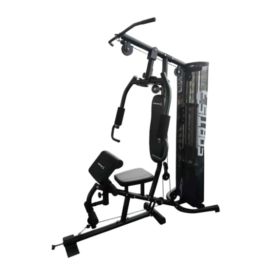
- Page 1 GYM STATION (45KG WEIGHTS) FSGYMSTN45A...
-
Page 2: Table Of Contents
Introduction Safety & Warnings Overview Assembly Notes... -
Page 3: Introduction
INTRODUCTION • Simply insert the weight pin into your desired weight and lift • Easy for doing pull ups, pullovers, pull-down using the lateral bars • Providing leg workouts as well by pulling with foot wrap • Adjustable bicep pad... -
Page 4: Safety & Warnings
SAFETY & WARNINGS General Safety Warnings Before using this equipment, it is essential that you read the entire user guide, including all warnings and safety instructions. Ensure you convey all such warnings and instructions to any other person using this product. Retain this user guide for future reference. Safety Important: Before beginning any exercise program, consult your physician. -
Page 5: Overview
OVERVIEW Add connecting piece... - Page 6 Part Description Part Description Base Frame M10 Nylon Nut Seat post M12 Nylon Nut Rear Stabiliser Fixed Pin for Weight Stack Seat Support Tube End Cap Φ60 Round Cap Upright Support Tube Φ60 Flat Cap Leg Curl Tube Φ50 Flat Cap Guiding Tube Φ25 Flat Cap Bridge Tube...
- Page 7 Hex Head Bolt M10 x 60mm Chain 8 Links Hex Head Bolt M8 x 15mm Hook Hex Head Bolt M10 x 40mm Weight Stack 8 Lbs Hex Head Bolt M10 x 45mm Weight Stack 10 Lbs Hex Head Bolt M10 x 75mm Cable for Lat Bar Hex Head Bolt M10 x 70mm Cable for Butterfly Arm...
-
Page 8: Assembly
ASSEMBLY Step A: Attach the seat post (02) to the Base Frame (01) using x2 hex head bolts (27), x4 curve washers (34) and x2 nylon nuts (39). - Page 9 Attach the seat support tube (04) to the seat post (02) using x2 hex head bolts (30), x4 flat washers (35) and x2 nylon nuts (39). Attach the rear stabilizer (03) to the seat support tube (04) using x2 hex head bolts (27), x4 curve washers (34) and x2 nylon nuts (39).
- Page 10 Step B: Attach the bracket for cloth cover (left side) (73) to the rear Stabiliser (03) and tighten using x2 hex head bolts (24), x2 washers (35A). Do the same for the bracket for the cloth cover (73) to the right side of the rear Stabiliser (03) and tighten using x2 hex head bolts (24), x2 washers (35A).
- Page 11 Slide both guiding tubes (07) through the rubber rings (48) and into the two holes on the rear Stabiliser (3) tighten from the bottom side using x2 curve washers (33) and x2 head hex bolts (22). Place the weight stack (64) into position ensure the guiding tubes (07) are fed through the holes.
- Page 12 Step C: Attach the bracket for cloth cover (73) into the bridge tube (08) using x4 hex head bolts (24) and attach the guiding tube (07) to the bridge tube (08) into using x2 hex head bolts (22).
- Page 13 Attach the bridge tube (08) to the upright support tube (05) and secure using x2 hex head bolts (30), x4 flat washers (35) and x2 nylon nuts (39). Attach the base frame (01) to the upright support tube (05). Following the diagram attach the x2 connection straps (78) and using a hex head bolt (30), hex head bolt (77) x2 flat washers (34) and x2 nylon nuts (39).
- Page 14 Step D: Attach the bracket for backrest (15) to the back cushion (59), tighten using x2 flat washers (35A) and x2 hex head bolts (24).
- Page 15 Attach the backrest cushion (59) to the upright support tube (05) by putting the screw on the bracket for backrest (15) into the hole in the upright support tube (05) and secure using a curve washer (34) and M10 nylon nut (39). Attach the seat (60) onto the seat support tube (04) by putting the screw on the bracket for seat into the holes and secure using x4 flat washers (35A), x4 hex head bolts (24).
- Page 16 Attach the x2 foam tube for leg curl (14) into the holes on leg curl tube (06) and front/upper bracket of seat support tube (04). Attach the x2 foam for leg curl tube (54) onto both sides of each foam tube for Leg Curl (14).
- Page 17 Step E: Attach the pull unit (09) to the bridge tube (08), insert the axle for pull unit (21) and secure using x2 Powder Metal Rings (31A), x2 Flat washers (36) and x2 Nylon Nuts (40) (refer to Step E diagram).
- Page 18 Attach the butterfly arm R (10R) to the right side of pull unit (09) using x2 powder metal rings (31), a hex head bolt (16) and x2 flat washers (36) and tighten using a x2 nylon nuts (40) Repeat the same procedure for the butterfly arm L (10L). Place the rubber stopper (70) onto the bracket on the upright support tube (05).
- Page 19 Attach the handlebar (11) onto the butterfly arm R (10R), tighten using x3 curve washers (33) and x3 hex head bolt (22). Repeat the procedure for butterfly arm L (10L) with the other handlebar (11L). Attach the x2 pulley brackets (20) onto both sides of the upright support tube (05) tighten using x2 hex head bolts (23), x4 flat washers (35) and x2 nylon nuts (39).
- Page 20 Step F: Attach the cable for lat bar (65) to the opening bracket at the front of the bridge tube (8). Note: The ball stopper of the Cable (65) should be underneath the bridge tube (8). Attach the cable (65) onto the pulley (49A) and put the cap for pulley (50) on either side of pulley (49A).
- Page 21 Draw the cable (65) downwards and around Pulley (49). Attach the Pulley (49) with the bracket for pulley (17) on both sides then tighten using a hex head bolt (25) and a nylon nut (39). Draw the cable (65) upwards and around Pulley (49). Attach the pulley (49) to bracket B and tighten using a hex head bolt (25) and a nylon nut (39) (refer to Step F diagram) Draw the cable (65) downwards between the two guiding tubes (07) and fully thread the bolt on the end of the cable (65) into the top opening on the select bar (19).
- Page 22 Step G: Attach one end of the cable for butterfly arm (66) to the hook on the right butterfly arm (10R), tighten using a hex head bolt (24), a flat washer (35A) and a nylon nut (38). Feed the cable (66) around the pulley (49) then attach the pulley (49) to the pulley bracket (20) on the right side of the upright support tube (05), tighten using a hex head bolt (25) and a nylon nut (39).
- Page 23 Feed the cable (66) upward and around pulley (49). Attach pulley (49) to the pulley bracket (20) on the left side of the upright support tube (05), tighten using a hex head bolt (25) and a nylon nut (39). Attach the end of the cable (66) to the hook on the left butterfly Arm (10L), tighten using a hex head bolt (24) and a flat washer (35A) and a Nylon Nut (38).
- Page 24 Step H: Bracket D Bracket E Attach the end with the stopper ball of the cable for lower pull bar (67) to the open bracket leg curl (6), around the underside of Pulley (49). Feed the cable (67) through the opening on the lower part of the seat post (02), around the pulley (49) from under side then draw the cable (67) upward and around the upper side of pulley (49).
- Page 25 Draw the Cable (67) upward and around the upper side of Pulley (49). Attach the Pulley (49) to the underside of Bracket for Pulley (17) set and tighten using a hex head bolt (25) and a nylon nut (39). Feed the Cable (67) downward and connect with bracket E on rear stabiliser (3) using chain links (61) and x2 Hooks (62).
- Page 26 Step I: Attach the bracket for the cloth cover L (73) to the bridge tube (08) and tighten using the x2 hex head bolts (24) and x2 flat washers (35A).
-
Page 27: Notes
NOTES... - Page 30 Need more information? We hope that this user guide has given you the assistance needed for a simple set-up. For the most up-to-date guide for your product, as well as any additional assistance you may require, head online to help.kogan.com...
Need help?
Do you have a question about the FSGYMSTN45A and is the answer not in the manual?
Questions and answers