Advertisement
Quick Links
Advertisement

Subscribe to Our Youtube Channel
Related Manuals for Fortis FXT-360A


Summary of Contents for Fortis FXT-360A
- Page 1 AUTOMATIC VARIABLE RESISTANCE MAGNETIC FLYWHEEL ELLIPTICAL CROSS TRAINER (FXT-360A) FSAEXT360AA...
- Page 3 SAFETY & WARNIGS Read all of the instructions in this guide before using this product. Retain this guide for future reference. Do not skip, substitute or modify any steps or procedures in this guide, as doing so could result in personal injury or product damage. •...
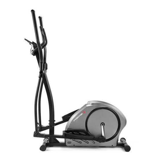
- Page 4 OVERVIEW...
- Page 5 Description Qty. Description Qty. Main frame Bolt M8 x 20 x S6 20 Washer d8 x Φ28 x 2 Front stabiliser Bolt M8 x 73 x 20 x H5 Universal joint Arc washer d8 x Φ20 x 2 x R30 L/R Crank Washer d8 Pedal supporting rod...
- Page 6 Description Qty. Description Qty. Screw ST4.2 x 19 x Φ8 Bushing Φ31.8 x Φ19.2 x 77.9 Bushing Φ14 x Φ8.3 x 59.5 Cover L/R Bushing 1 Φ32 x 3 x Φ28 x 16 Cover L/R x Φ14.3 Screw M5 x 10 x Φ9 End cap Φ60 x Φ70 x 95 Cover L/R Screw ST3 x 10 x Φ5.6...
- Page 7 ASSEMBLY Step 1: Secure front stabiliser (2) and rear stabiliser (7) to main frame (1) with bolt (3), arc washer (4), washer (5) and nut (6) separately.
- Page 8 Step 2: Remove the pre-installed bolt (9), washer (5), arc washer (11) and washer (10) from the mainframe (1), please reserve for pending step. Connect trunk wire (13) with sensor wire (15). Secure the handlebar post (8) to the mainframe (1) with bolt (9), washer (5), arc washer (11) and washer (10).
- Page 9 Step 3: Remove the pre-installed bolt (17), washer (5) and washer (18) from the handlebar post (8), please reserve for pending step. Insert the swing rod (16L/R) and universal joint (21) to the fixed axle of handlebar post (8) and crank (22) separately.
- Page 10 Step 4: Secure pedal (25L/R) to pedal supporting rod (23L/R) with bolt (24), washer (26) and nut (27) separately.
- Page 11 Step 5: Connect the console wire (32a) with trunk wire (13). Then secure the console (32) to the handlebar post (8) with the bolt (33). Remove the pre-installed bolt (30) and washer (5) from the handlebar post (8). Secure the middle handlebar (29) to the handlebar post (8) with the bolt (30) and washer (5).
- Page 12 Step 6: Insert handlebar (34L/R) into the swing rod (16L/R) separately. Secure the handlebar (34L/R) with bolt (35), arc washer (11) and nut (27) separately.
- Page 13 Step 7: Buckle up the cover (38L) and cover (38R) to the pedal supporting rod (23L). Then fix it with screw (37), as the diagram A. Buckle up the cover (39L) and cover (39R) to the pedal supporting rod (23R). Then fix it with screw (37), as the diagram B.
- Page 14 Step 8: Buckle up the cover (41L) and cover (42L) to the universal joint (21). Then fix it with screw (40), as the diagram A. Buckle up the cover (41R) and cover (42R) to the universal joint (21). Then fix it with screw (40), as the diagram B.
- Page 15 Step 9: Buckle up the cover (44L) and cover (43L) to the swing rod (16L). Buckle up the cover (44R) and cover (43R) to the swing rod (16R). Before using the unit, first, insert the round plug of the adaptor (66) into the hole in the mainframe (1).
- Page 16 PROGRAMS Motorised Computer Operation There are 21 programs in the computer. A: 1 manual setting B: 10 preset program profiles (PROGRAM: P1-P10) P1: Rolling P2: Valley P3: Fat burn P4: Ramp...
- Page 17 P5: Mountain P6: Interval P7: Cardio P8: Endurance P9: Slope P10: Rally...
- Page 18 C: 5 custom user setting programs (CUSTOM: P11 ~ P15) • Record the user's data of 5 User Setting Programs. • Display Speed (RPM), TIME and WATT, CAL and DIST, at the same time...
- Page 19 D: 1 watt control program (WATT PRO: P16) E: 4 Heartrate control program: (PULSE PRO: P17-P20) • 55% HR, 75% HR, 95% HR and TARGET HR • HR = Heartrate Note: The computer will turn off automatically if there is no operation, speed signal and pulse signal over 4 minutes.
- Page 20 BUTTONS ENTER In “stop” mode, press ENTER button to enter into program selection and setting value which flash in the related window. • When selecting a program, press Enter to confirm selection. • When in setting, press ENTER to confirm the value that you would like to preset. In “start”...
-
Page 21: Operation
OPERATION 1. Turn on the computer Plug in one end of the adaptor to the AC electrical source and connect the other end to the computer. The computer will beep and enter into the initial mode. 2. Program select and value setting Manual Program and Preset Program P1-P10 •... - Page 22 Watt Control Program (WATT PRO: P16) • Press UP, DOWN to select the watt control program. • Press ENTER to confirm the selected watt control program and enter into time setting window. • The time will flash and then press UP, DOWN button to set up the desired time, press ENTER to confirm the value.
- Page 23 • The calories will flash and then press UP, DOWN button to set up the desired calories to be consumed. Press ENTER to confirm the value. • The age will flash and then press UP, DOWN button to set the user's age. Press ENTER to confirm the value.
- Page 24 3. Pulse recovery test The pulse recovery test is to compare your heart rate before and after exercise. It is a target to determine your heart strength via the measuring. Please do the test as below: • Both your hands hold the pulse sensor or via wireless transmitter belt to test the pulse (if applicable), the computer will display your current pulse value.
-
Page 25: Specifications
SPECIFICATIONS Equipment Speed KM/H Showing your current speed. Range: 0.0~99.9 KM/H. Showing the current rotate per minute. Range: 0~999. The accumulative exercise time, range: 0:00~99M59S. The preset time range is 5:00~99M00S. The computer will start to count down from preset time to 0:00 with the average time for each resistance Time level. - Page 26 NOTES...
- Page 27 NOTES...
- Page 28 Need more information? We hope that this user guide has given you the assistance needed for a simple set-up. For the most up-to-date guide for your product, as well as any additional assistance you may require, head online to help.kogan.com...
Need help?
Do you have a question about the FXT-360A and is the answer not in the manual?
Questions and answers