
Related Manuals for Electrolux thermaline 588213


Summary of Contents for Electrolux thermaline 588213
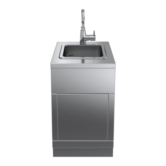
- Page 1 Sink Installation and operating manual * 599A0V400 - 82.8160.01- 2021.07 *Original instructions...
- Page 2 Foreword Read the following instructions, including the warranty terms before installing and using the machine. Visit our website www.electroluxprofessional.com and open the Support section to: Register your product Get hints & tips of your product, service and repair information The installation, use and maintenance manual (hereinafter Manual) provides the user with information necessary for correct and safe use of the machine (or “appliance“).
-
Page 3: Table Of Contents
Contents A WARNING AND SAFETY INFORMATION....................5 General information ........................5 Personal protection equipment ......................6 General safety ..........................6 General safety rules ........................7 Safety signs to be placed near the machine area ................. 8 Transport, handling and storage ...................... 9 Installation and assembly ....................... - Page 4 Cleaning the appliance and accessories ..................25 Stainless steel surfaces ....................... 25 Colored surfaces ........................26 Descaling ..........................26 MAINTENANCE AND CUSTOMER SERVICE ................... 26 Introduction ..........................26 Maintenance intervals........................26 J.2.1 Preventive Maintenance ..................... 26 Informations for maintenance ......................26 Repair and extraordinary maintenance ....................
-
Page 5: Awarning And Safety Information
WARNING AND SAFETY INFORMATION General information To ensure safe use of the machine and a proper understanding of the manual it is necessary to be familiar with the terms and typographical conventions used in the documentation. The following symbols are used in the manual to indicate and identify the various types of hazards: WARNING Danger for the health and safety of operators. -
Page 6: Personal Protection Equipment
Personal protection equipment Summary table of the Personal Protection Equipment (PPE) to be used during the various stages of the machine's service life. Stage Protective Safety Gloves Glasses Safety garments footwear helmet ● ○ ○ — — Transport — ● ●... -
Page 7: General Safety Rules
• Do not use products (even if diluted) containing chlorine (sodium hypochlorite, hydrochloric or muriatic acid, etc.) to clean the appliance or the floor under it. • Do not use metal tools to clean steel parts (wire brushes or Scotch Brite type scouring pads). -
Page 8: Safety Signs To Be Placed Near The Machine Area
– well lit. For the Customer's complete information, the residual risks remaining on the machine are indicated below: such situations are deemed improper and therefore strictly forbidden. Residual risk Description of hazardous situation Slipping or falling The operator can slip due to water or dirt on the floor Burns/abrasions (e.g. -
Page 9: Transport, Handling And Storage
Danger Meaning caution, hot surface danger of electrocution (shown on electrical parts with indication of voltage) End of use • When the appliance is no longer to be used, make it unusable by removing the mains power supply wiring. Transport, handling and storage •... -
Page 10: Machine Space Limits
Machine space limits • A suitable space must be left around the appliance (for operations, maintenance, etc.). • This space must be increased in case of use and/or transfer of other equipment and/or means or if exit routes are necessary inside the workplace. A.10 Positioning •... -
Page 11: Machine Cleaning And Maintenance
Preventive maintenance • In order to ensure the safety and performance of your equipment, it is recommended that service is undertaken by Electrolux Professional authorised engineers every 12 months, in accordance with Electrolux Professional Service Manuals. Please contact your local Electrolux Professional Service Centre for further details. -
Page 12: Machine Disposal
See the data plate located in the lower right corner to identify the appliance (see fig. below). Electrolux Professional AG - Allmendstrasse 28, CH - 6210 Sursee MW freq... -
Page 13: Appliance And Manufacturer's Identification Data
An example of the marking or data plate on the machine is 850 mm given below: 900 mm Electrolux Professional AG - Allmendstrasse 28, CH - 6210 Sursee 3 - Machine type Sink 4 - Size / Zones / Details... -
Page 14: Copyright
Disposal of packing Manufacturer Electrolux Professional SpA or any other The packing must be disposed of in compliance with the service centre authorised by Electrolux current regulations in the country where the appliance is used. -
Page 15: Characteristics Of Personnel Enabled To Operate On The Machine
D.10 Characteristics of personnel enabled to • adequate general basic education and technical knowledge for reading and understanding the contents of the manual, operate on the machine including correct interpretation of the drawings, signs and The Customer is responsible for ensuring that persons pictograms;... - Page 16 Floor installation options: 3. Against the wall on steel plinth or 1. On steel plinth or adjustable feet 2. On concrete plinth adjustable feet 800 / 850 / 900 800 / 850 / 900 800 / 850 / 900 660 / 710 / 760 660 / 710 / 760 730 / 780 / 840 4.
-
Page 17: Installation And Connection Diagram
Installation and connection diagram 24 4 15 0 13 0 EQ = Potential equalisation WI = Water inlet CWI = Cold water connection HWI = Hot water connection D = Drain... -
Page 18: Accessing The Appliance's Internal Components
Accessing the appliance’s internal components INSTALLATION AND ASSEMBLY Appliance type • on steel plinth • on concrete plinth The appliances are suitable for setting up as single appliances or as a group of appliances. They can be positioned freely in the space provided, side by side, against a wall or back-to-back. -
Page 19: Positioning On Concrete Plinth
G.4.2 Positioning on concrete plinth 1. Transport the appliance on its transport pallet directly in front of the point of installation. 2. Remove the pre-cut plate at the bottom of the appliance. (for access, see F Installation DIAGRAMS). 3. Lift the unit on one side so that all installation connections are inside the appliance. -
Page 20: Securing Or Adjusting To The Floor (Optional)
G.4.4 Securing or adjusting to the floor (optional) If you need to secure it to the floor, the appliance comes with compatible adjustable feet. We recommend you adjust the feet so you end up with a working height of 900 mm. Level the unit with a spirit level. Attaching the unit with screws Attaching the unit by welding The feet have metal plates which may be secured to the floor... -
Page 21: Fastening Multiple Appliances Together
3. Remove the transport pallet. 4. Carry the appliance on the lifting cart to the prepared position on the wall and lift it to the correct height. 5. Remove the outer protective film and the edge covers, taking care not to scratch the surface of the appliance. Very slowly pull off the protective film on the stainless steel surfaces, without ripping, to prevent any adhesive residue. -
Page 22: Side Panels And Base Models
Using a solid tool, break nuts C from connecting rail D. Seal the whole length of the joint with long lasting Insert connecting rail D into the gap between the top, silicone (we recommend grey junction sealing, making sure marking E is pointing forwards. code: 059611). -
Page 23: Fixing The Side Panels
Fixing the side panels G.8.1 Panels with a 12,5 mm overhang Attach connecting rails B and C with the supplied Bring the side panel D into position. screws A. Make sure marking on part B on the rail is Put the 5 hooks of the panel F into the slots E. pointing forwards. -
Page 24: Side Cover Without Overhang
G.8.2 Side cover without overhang The side cover should only be used as a closing off against the wall, against a niche and in between appliances (provided that these have the same dimensions). Standard cover has pre-cuts that you can adapt to the appliances according to the left/right side. Fit the 4 cage nuts A into the dedicated slots on the Attach connecting rails C and D with the supplied frame. -
Page 25: Handrail (Optional)
CAUTION Handrail (optional) If the handrail is present, do not place on it For correct assembly/disassembly of the handrail, refer to the more than 25 kg per meter of structure. dedicated installation instructions. CONNECTING THE WATER SUPPLY WARNING Before connecting the filter, allow a certain amount of water to run in order to clear the pipe of any waste matter. - Page 26 This list is just a short description; for detailed information, please read the service manual. Should none of the measures listed below resolve the fault or if an error occurs that is not described here, disconnect the appliance from the mains supply (gas, water, electricity) and immediately contact the Electrolux Professional Customer Care Service.
- Page 27 What to do if Problem Cause Solution Water supply No water is coming into the tank • The local water tap is off • Open the water tap • The tank’s water tap is blocked • Clean the outlet tap MACHINE DISPOSAL WARNING compressor contains lubricant oil and refrigerant fluid which...
- Page 30 Electrolux Professional AG Allmendstrasse 28 CH - 6210 Sursee www.electroluxprofessional.com...
Need help?
Do you have a question about the thermaline 588213 and is the answer not in the manual?
Questions and answers