Table of Contents
Advertisement
Advertisement
Table of Contents

Related Manuals for Laguna Tools REVO 24-36


Summary of Contents for Laguna Tools REVO 24-36
- Page 1 Original Instructions...
- Page 2 EN 61000-4-4: 2012 Electrical fast transient/burst requirements (EFT/Burst) EN 61000-4-6: 2014 Immunity to conducted disturbances, induced by radio-frequency fields (CS) Responsible for the documentation: Head Product Management, Laguna Tools Inc. Name : Torben Helshoj Responsibility Authorized Signature Date : Oct.
- Page 3 Name : Torben Helshoj Responsibility Authorized Signature Date : Oct. 15, 2021 Place : Laguna Tools Inc. 2072 Alton Parkway, Irvine, California 92606, USA Telephone: +1 800 234-1976 Fax: +1 949 474-0150...
-
Page 4: Table Of Contents
Table of contents. Page number Safety Rules Warranty Noise emission Specification sheet Receiving your machine Introduction to your machine Parts of the machine What you will receive with the machine Where to locate your machine Unpacking your machine Assembly and setup Maintenance Troubleshooting Electrical drawing... -
Page 5: Safety Rules
SAFETY RULES KEEP GUARDS IN PLACE and in working order. SECURE WORK. Use clamps or a vise to hold work when practical. It's safer than using your REMOVE ADJUSTING KEYS AND WRENCHES. hand and it frees both hands to operate tool. Form habit of checking to see that keys and ad- justing wrenches are removed from tool before DON'T OVERREACH. - Page 6 Location of warning signs...
- Page 7 Wood lathe Wood turning lathes are typically used to shape wood into cylindrical profiles. Objects made on a wood lathe include such items as furniture legs, lamp posts, baseball bats, bowls and other ornamental forms. Wood lathe tooling consists of fixturing and securing devices for the work piece, a moveable tool rest, and hand-held cutting tools in the form of long handled gouges, skews, scrapers, and parting tools.
- Page 8 Locking the lathe It is strongly recommended that the lathe is never left unattended in the unlocked condition. To lock the machine it is recommended that a cover (not supplied) is made to lock the control panel. We have supplied two concepts for locking the panel (see below). The cover can be made from wood or plastic, two covers (not supplied) are made to lock the control panels on both headstock and remote controller.
-
Page 9: Warranty
Laguna Tools guarantees all new machines sold to be free of manufacturer's defective workmanship, parts, and materials. We will repair or replace, without charge, any parts determined by Laguna Tools, Inc. to be a manufacturer's defect. We require the defective item/part to be returned to Laguna Tools. In... -
Page 10: Noise Emission
Noise Emission. Equivalent A-weighted Sound pressure level according to EN ISO 3746: 75.66 dB(A) Uncertainty, K in decibels: 4.0 dB (A) according to EN ISO 4871 The figure quoted is emission levels and are not necessarily safe working levels. Whilst there is a correlation between the emission and exposure levels, this cannot be used reliably to determine whether or not further precautions are required. -
Page 11: Specification Sheet
Specification sheet. Motor Induction,1420RPM, 3 HP 230V 3Ph Voltage 230v 50hz 1Ph input Recommended 15 amp breaker size Swing over bed 24" (609mm) Swing over banjo 19.75" (501mm) Outboard swing 38" (965mm) Distance between 36" (914mm) centers Floor to spindle 44.5"(1130mm) center Floor to bed height... -
Page 12: Receiving Your Machine
All damage must be noted on the delivery documents and signed by you and the delivery driver. You must then contact the seller (Laguna Tools) as soon as practical. If damage is found after delivery, contact the seller as soon as is practical. -
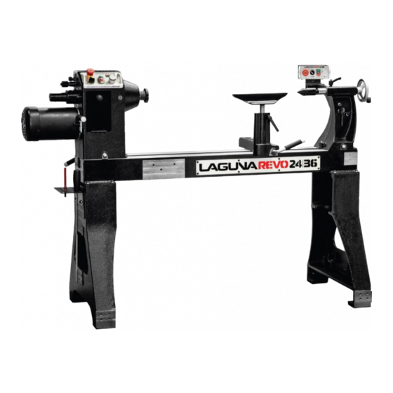
Page 13: Introduction To Your Machine
Introduction to lathes. This machine is designed to give you years of safe service. Read this owner's manual in its entirety before assembly or use. Parts of the lathe. The lathe consists of a number of major parts, which are discussed in this manual. Take the time to read this section and become familiar with the machine. - Page 14 M30 x 3.5 Spindle Thread for Australia. Article No. LAGUNA-L-0016 Weight 242kg Series No. Year LAGUNA TOOLS 2072 Alton Parkway. Irvine, CA 92606 www. lagunatools.com Lathe Bed. The bed is a machined heavy steel welded construction. Underside of lathe bed...
- Page 15 Lathe legs. The Legs are cast iron, and their heavy construction gives the machine a low center of gravity and ensures that it is very stable. The legs are supplied with adjustable feet to allow the machine to be leveled. Legs with adjustable feet assembled Head stock.
- Page 16 Headstock removed from the Head or remote selection switch Tail stock. The tail stock is of cast iron construction, and the spindle has a travel of 4 1/2 in. It can accommodate centers and other tools which have a number 2 Morse Taper. The tail stock can be moved to any position on the lathe bed and locked to suit the job at hand.
- Page 17 Tool rest assembled to the bed Tool rest Electrical system. 220V: The electrical control system (VFD) is housed at the back of the head stock, The VFD converts single phase 220v to three phase. There is a speed readout at the front of the lathe with controls to fine adjust the RPM of the spindle.
-
Page 18: What You Will Receive With The Machine
Tool storage. A tool storage bracket which can be mounted on either leg. Tool storage bracket What you will receive with the lathe. - Page 19 Head stock Tool rest Tail stock Drive &live center storage Tool storage Leg Banjo Adjustable feet Remote controller Face plate Tool rack Rotating center Adjustable feet Tail stock bracket...
- Page 20 Removal tool Drive center Knock out rod Head stock bracket Tail stock knob Tool rest comes fitted to banjo Remote brackets and hardware...
-
Page 21: Where To Locate Your Machine
Where to locate your machine. Before you remove your machine from the packaging, select the area where you will use your machine. There are no hard and fast rules for its location, but below are a few guidelines: 1. There should be sufficient area at the front of the machine to allow you to work on it comfortably. - Page 22 Second leg Top packaging removed 2. Open the box and remove the parts sent with the lathe including the first leg. Note. The legs are heavy and caution must be exercised. They are cast iron and if dropped they will break. 3.
-
Page 23: Assembly And Setup
Assembly and setup. The machine comes mostly assembled. You will have to assemble the legs, headstock, tailstock, tool storage and the tool rest to the bed of the machine. Note. It is recommended that the head stock, tool rest and tailstock be removed from the bed of the lathe to ease assembly (Covered later in the manual). - Page 24 Lay the bed on 2" X 4" timbers in the upside down position. Lift the legs to the vertical position and lower them onto the bed. Secure with the fixing screws provided. Note. At least two people will be needed to perform the assembly, one to hold the leg in position and one to fit the fixing screws.
- Page 25 Assembled lathe If you decide to fit the tool rest after fitting the tail stock, follow the below procedure. Fit the tool rest onto the bed of the lathe ensuring that the washer recess fits into the slot in the bed. Fit the banjo onto the bed with the bolt through the washer and assemble the nut onto the thread.
- Page 26 Tool rest clamp handle Washer assembled in position Banjo clamp handle Fitting the stock knob. Screw the tail stock knob onto the tail stock handle. Tail stock knob Tail stock handle Connecting the electrical supply. Ensure that the electrical supply corresponds with that of the machine (Single phase 220V).
- Page 27 Fitting the remote controller. The remote controller can be fitted in either of two positions, attached to the tail stock or attached to the tailstock leg. Fitting the remote controller to the tailstock leg. 1. Fit the support plate to the bed by removing the two clamp bolts and with the two clamp screws secure the support plate.
- Page 28 Note. The headstock can only be controlled by one controller and you must select which controller is used by selecting with the controller selection switch. Controller selection switch Cleaning the machine. Remove the rust protection grease with WD 40 or a similar solvent. It is important that you remove all the grease and re-lubricate with a Teflon-based lubricant.
- Page 29 Fitting the rotating center. Rotating center Ensure that the bore of the tail stock is clean. The rotating center has a number 2 Morse Taper that fits into the tail stock. Push the center into the tail stock bore firmly, and ensure that it is securely located.
- Page 30 Drive center removal shaft Headstock drive center Fitting the face plate. Reverse the removal procedure, described earlier. Lathe controls. Emergency stop button The emergency stop button will lock in the OFF position when fully depressed. To reset it, twist clockwise and it will pop out. Forward / reverse switch.
- Page 31 Emergency stop button Start / stop buttons Speed display Forward / reverse switch Variable speed adjustment knob Head stock clamp lever Head stock clamp lever. The head stock clamp lever allows the head stock to be released and moved to any position on the lathe bed.
- Page 32 Variable speed adjustment knob. Increase speed Decrease speed The Variable speed adjustment knob adjusts the spindle speed. Turns clockwise to increase the speed, turns counter-clockwise to decrease the speed High / low speed. The lathe has two sets of pulleys for high (135 - 3500 RPM) and low (50 - 1300 RPM) speed ranges.
- Page 33 Pulleys and drive belt Pulley cover Motor lock handle Motor adjustment handle Indexing the spindle. The spindle has 3 sets of indexing holes 14 / 36 / 48. The selection plunger is located at the end of the head stock. To move between the 3 sets of holes, loosen the clamp knobs and slide the indexing plunger assembly to align with the selected hole set.
- Page 34 Clamping knobs Hole selection indicator Indexing holes Hole selection Indexing plunger Indexing plunger engaged Indexing plunger disengaged...
-
Page 35: Maintenance
Maintenance. General. Keep your machine clean. At the end of each day, clean the machine. Wood contains moisture, and if sawdust or wood chips are not removed they will cause rust. In general, we recommend that you only use a Teflon-based lubricant on the lathe. Regular oil attracts dust and dirt. - Page 36 the tailstock should be slid along the bed to check for any area that it binds in the bed slot. The same procedure as above should be conducted on the head stock should it be required. Note. It is very unlikely that the headstock will require adjustment as it is not moved as often as the tailstock, so has less tendencies for ware.
- Page 37 Center point alignment. The tailstock has two clamp screws that are accessible from the top of the tailstock. The clamp screws hold the slide plate to the tailstock casting. There is clearance in the holes that allows the tailstock to be moved in relation to the slide plate. The headstock also has two clamp screws, but one is accessible from under the headstock.
-
Page 38: Troubleshooting
Troubleshooting. Lathe will not start. 1. Check that the start switch is in the correct position. 2. Check that the electrical power cord is plugged into the power outlet. 3. Check that the electrical supply is on (reset the breaker). 4. - Page 39 Machine vibrates. 1. Machine not level on the floor. Re-level the machine ensuring that it has no movement. 2. Damaged drive belt. Replace the belt. 3. Job is not balanced. Change to slower speed and/ or balance the job. 4. Damaged pulley. Replace the pulley. 5.
-
Page 40: Electrical Drawing
Electrical drawing. - Page 41 Wiring diagram for control panel on headstock.
- Page 42 Wiring diagram for remote control.
-
Page 43: Exploded View Drawings
Exploded view drawings and parts list. - Page 44 Parts List for REVO 24│ 36 Lathe Index Part Number Item Description Specification PLAREVO1836-101 PLAREVO1836-102 Spindle Pulley PLAREVO1836-103 Spring PLAREVO1836-104 Spindle Lock Plunger PLAREVO1836-105 Locking Collar PLAREVO1836-106 Bearing Nut PLAREVO1836-107-UK Door PLAREVO2436-220-108A Tailstock...
- Page 45 PLAREVO1836-109 Motor Pulley PLAREVO2436-220-110 Motor Plate PLAREVO1836-111 Headstock Locking Handle Headstock PLAREVO2436-220-112-UK PLAREVO1836-113-UK 3" Faceplate PLAREVO1836-114 Clamp Bolt PLAREVO1836-115 Sleeve PLAREVO1836-116 Rubber Sleeve PLAREVO1836-117 Knob PLAREVO1836-118 Headstock Adjusting Plate PLAREVO1836-119 Clamp PLAREVO1836-120 Lock Handle PLAREVO2436-220-121 Control Panel PLAREVO1836-122 Handwheel Motor PLAREVO2436-220-123-UK PLAREVO1836-124 Spur Center...
- Page 46 PLAREVO1836-146 Lead Screw PLAREVO1836-147 Stop Bolt PLAREVO1836-150 Tool Caddy PLAREVO1836-151 Knockout Rod PLAREVO1836-152-UK Braking Resistor Cord PLAREVO1836-153 Lock Handle PLAREVO1836-154 Control Box PLAREVO2436-220-155 Control Cord PLAREVO1836-156 Tailstock Tool Caddy PLAREVO1836-157 Hex Cap Screw M6x6 PLAREVO1836-158 Door Hinge PLAREVO1836-159 Speed Knob PLAREVO1836-160 Rubber Sleeve PLAREVO1836-161...
- Page 47 PLAREVO1836-184 Wave Washer 6205 PLAREVO1836-185 6x6x30 PLAREVO1836-186 8x7x25 PLAREVO1836-187 8x7x60 PLAREVO2436-220-188 E-Ring PLAREVO1836-189 E-Ring PLAREVO1836-190 E-Ring PLAREVO1836-191 C-Ring PLAREVO1836-192 Socket Head Cap Screw 1/4-20UNCx1" PLAREVO1836-193 Hex Cap Screw 3/8-16UNCx1/2" PLAREVO2436-220-194 Washer, Lock-Int. Tooth PLAREVO1836-195 Socket Head Cap Screw 3/8-16UNCx1" PLAREVO1836-196 Knob PLAREVO1836-197 Socket Head Cap Screw...
- Page 48 PLAREVO1836-1120 Socket Head Button Screw M8x30 PLAREVO1836-1121 Socket Head Button Screw M8x45 PLAREVO1836-1122 Socket Head Cap Screw 5/16-18UNCx1/2" PLAREVO2436-220-1123 Poly-V Belt PJ8-200 PLAREVO1836-1124 Set Screw M6x6 PLAREVO1836-1125 Set Screw 5/16-18UNCx1/4 PLAREVO1836-1126 Socket Head Button Screw 3/8-16UNCx5/8" PLAREVO1836-1127 Screw M3x12 PLAREVO1836-1128 Spacer PLAREVO1836-1129 Handle...
- Page 49 PLAREVO2436-220-1157 Relay PLAREVO2436-220-1158 Socket Head Button Screw M3x6 PLAREVO2436-220-1159 Remote Control Panel PLAREVO2436-220-1160 Flat Washer D4xD20x2t PLAREVO2436-220-1161 Clamp Bolt Remote Control Box PLAREVO2436-220-1162-UK PLAREVO2436-220-1163 Bracket PLAREVO2436-220-1164 Remote Control Cord PLAREVO2436-220-1165 Screw M4x12 PLAREVO2436-220-1166 Screw M3x6 PLAREVO2436-220-1167 Washer, Lock-Int. Tooth 1/4" PLAREVO2436-220-1168 Hex Cap Screw 1/4-20UNCx3/8"...
- Page 50 Optional Headstock Guard Index Part Number Item Description Specification PLAREVO1836-201 Plunger PLAREVO1836-202 Retaining Collar PLAREVO2436-203 Guard PLAREVO1836-1125 Set Screw 5/16-18UNCx1/4"...
- Page 52 Optional 20" Bed Extension with Riser Block and Tool Rest Extension Index Part Number Item Description Specification PLAREVO1836-301 20" Bed Extension PLAREVO1836-147 Stop Bolt PLAREVO1836-303 Socket Head Button Screw 3/8-16UNCx1" PLAREVO1836-304 Riser Block PLAREVO1836-305 Riser Block Locking Handle PLAREVO1836-306 Riser Block Adjusting Plate PLAREVO1836-119 Clamp PLAREVO1836-114...
- Page 53 Optional 12" Swing-Away Extension Index Part Number Item Description Specification PLAREVO1836-401 12" Bed Extension PLAREVO1836-402 Draw Latch Assembly PLAREVO1836-403 Hinge PLAREVO1836-404 PLAREVO1836-406 Socket Head Cap Screw M6x1.0x12mm PLAREVO1836-407 Phillips Flat Head Screw M5x0.8x12mm PLAREVO1836-320 Socket Head Button Screw 3/8-16UNCx1-1/4" PLAREVO1836-409 Set Screw 3/16-24UNCx3/8"...
- Page 54 Optional Comparator Index Part Number Item Description Specification PLAREVO1836-501 Center PLAREVO1836-502 Lock Handle...
- Page 55 Optional Industrial Flood Light Index Part Number Item Description Specification PLAREVO1836-601 Work Light PLAREVO1836-602 Screw M4x0.7x20mm...
- Page 57 Optional Inverter for Vacuum Index Part Number Item Description Specification PLAREVO1836-801 Connecting Shaft PLAREVO1836-802 Vacuum Adaptor Body PLAREVO1836-803 Cover PLAREVO1836-804 Vacuum System Box PLAREVO1836-805 Plate PLAREVO1836-806 Vacuum Generator Bracket PLAREVO1836-807 Vacuum System Bracket PLAREVO1836-808 O-Ring PLAREVO1836-809 Vacuum Generator PLAREVO1836-810 Silencer PLAREVO1836-811 L-Type Fitting PLAREVO1836-812...
- Page 59 Optional Deluxe Wheel System Index Part Number Item Description Specification PLAREVO1836-901 Support Bracket-Right PLAREVO1836-1115 Lock Washer 3/8" PLAREVO1836-195 Socket Head Cap Screw 3/8-16UNCx1" PLAREVO1836-904 Support Bracket-Left PLAREVO1836-905 Nylon Insert Lock Nut M8x1.25 PLAREVO1836-906 Support Bracket PLAREVO1836-907 Socket Head Cap Screw M8x1.25x45mm PLAREVO1836-1146 Socket Head Button Screw...
Need help?
Do you have a question about the REVO 24-36 and is the answer not in the manual?
Questions and answers