Table of Contents
Advertisement
Advertisement
Table of Contents

Related Manuals for Laguna Tools Platinum 18/47 Series


Summary of Contents for Laguna Tools Platinum 18/47 Series
- Page 1 Platinum Series 18/47 Lathe Manual LAGUNA TOOLS 2072 Alton Parkway Irvine, California 92606 Ph: 800.234.1976 Model Numbers: L A175017 www.lagunatools.com © 2018, Laguna Tools, Inc. LAGUNA® and the LAGUNA Logo® are the registered trademarks of Laguna Tools, Inc. All rights reserved.
-
Page 3: Table Of Contents
Table of contents Page number Safety Rules Warranty Noise emission Specification sheet Receiving your machine Introduction to your machine Parts of the machine Where to locate your machine Unpacking your machine Assembly and setup Maintenance and troubleshooting Exploded view drawings... -
Page 4: Safety Rules
Safety Rules. As with all machinery there are certain hazards involved with the operation and use. Using it with caution will considerably lessen the possibility of personal injury. However, if normal safety precautions are overlooked or ignored, personal injury to the operator may result. If you have any questions relative to the installation and operation, do not use the equipment until you have contacted your supplying distributor. -
Page 5: Warranty
Machines sold through dealers must be registered with Laguna Tools within 30 days of purchase to be covered by this warranty. Laguna Tools guarantees all new machines and accessories sold to be free of manufacturers’... -
Page 6: Noise Emission
Noise emission. Notes concerning noise emission: Given that there exists a relationship between noise level and exposure times, it is not precise enough to determine the need for supplementary precautions. The factors affecting the true level of exposure to operators are clearly the amount of time exposed, the characteristics of the working environment, such as other sources of dust and noise, etc. -
Page 7: Receiving Your Machine
All damage must be noted on the delivery documents and signed by you and the delivery driver. You must then contact the seller [Laguna Tools] as soon as practical. If damage is found after delivery, contact the seller as soon as is practical. - Page 8 Lathe bed. The bed is a machined heavy casting.
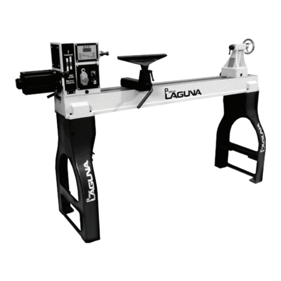
- Page 9 Head stock Legs Lathe legs. The Legs are cast iron, and there heavy construction gives the machine a low centre of gravity, and ensures that it is very stable. Head stock The head stock is cast iron and houses the variable speed control and motor. The speed can be adjusted between 0 -1200 [low] 0-3200 [high].
- Page 10 Tool rest. The tool rest can be moved to any position on the lathe bed and locked to suite the job in hand. Electrical System. The electrical control system is housed inside the head stock, and a power cord with a 3 pin plug is provided. What you will receive with your lathe.
-
Page 11: Where To Locate Your Machine
Support feet Face plate Tail stock centre removal rod Head stock Where to locate your machine. Before you remove your machine from the packaging, select the area where you will use your machine. There are no hard and fast rules for its location, but below are a few guidelines: 1. - Page 12 1. Dismantle the box, including the sides as this will ease access to the machine. 2. Remove the bolts that secure the legs to the bed of the machine. If you do not have a lifting hoist or fork lift, you may find it easer to remove the bolts that secure the legs together, and remove one leg at a time.
-
Page 13: Assembly And Setup
Assembly and setup. The machine comes mostly assembled. You will have to assemble only the legs and the tool rest to the bed of the machine. Note. It is recommended that the head stock is removed from the bed of the lathe to ease assembly [Covered later in the manual]. - Page 14 Fitting the leveling feet. Lift one leg onto 2 blocks of wood [Approx 4 in high]. Fit the two leveling bolts. Remove the With the machine in it’s final wood. Repeat the procedure for the other leg. position, level machine. Lathe with leveling feet fitted Leveling foot fitted Re fit the head stock to the bed of the lathe.
- Page 15 Tool rest clamping nut and washer Tool rest assembled Connecting the electrical supply. Ensure that the electrical supply corresponds with that of the machine [Single phase 220V].It is recommended that you use a 30-amp main breaker. Note. A qualified electrician must carry out the installation. Cleaning the machine.
- Page 16 Face plate locking / unlocking rod Face plate allen set screws Index pin Drive centre fitted Clean Morse taper Fitting the drive centre in the head stock. To remove the face plate from the head stock spindle. Loosen the two allen set screws.
- Page 17 Note. Do not leave the Drive centre removal shaft in the head stock with the machine running. Fitting the face plate. Reverse the removal procedure, described earlier. Note. The face plate allen screws, must be tight at all times, as the face plate can unscrew when the spindle direction is reversed.
- Page 18 Motor clamp handle Electrical controls Power on-off switch. Electrical reset button The on / off switch activates or de activates the Spindle direction switch Electrical system including the motor. Electrical reset button. Should the electrical system become overloaded the internal breaker will trip. To reset, correct the reason for the overload and then reset the system by pressing the reset button.
- Page 19 Starting the lathe: It is very important that the following procedure is followed when starting and stopping the lathe. If the procedure is not followed, then the electrical system will be strained and failure will occur. Forward, off, reverse switch in off 1.
- Page 20 (variable frequency converter) when you have completed your work. Spindle indexing lock pin. The head stock has 3 tapped holes, one untapped hole, and the spindle has 8 holes. The untapped hole in the headstock is used in conjunction with the plane end of the index pin to lock the spindle when rotation needs to be locked temporary, such as removing the face plate.
-
Page 21: Maintenance And Troubleshooting
Maintenance. General. Keep your machine clean. At the end of each day, clean the machine. Wood contains moisture, and if sawdust or wood chips are not removed they will cause rust. In general, we recommend that you only use a Teflon based lubricant on the lathe. Regular oil attracts dust and dirt. - Page 22 Motor overheats. The motor is designed to run hot, but should it overheat it has an internal thermal overload protector that will shut it down until the motor has cooled, and then it will reset automatically. If the motor overheats, wait until it has cooled and restart. If the motor shuts down consistently check for the reason.
- Page 26 Q’TY Q’TY DESCRIPTION DESCRIPTION STAND SCREW M5x10 BRACKET SCREW M5x12 C-RING C-19 SPRING WASHER 5 LEVER BAFFLE POWER CORD WASHER 8 STRAIN RELIEF CAP SCREW M8x35 MOTOR C-RING C-19 KNOCKOUT ROD SET SCREW M5x10 SCREW M5x12 BAFFLE PLATE TOOL REST BODY KEY 6X6X48 TOOL REST CAP SCREW M10x30...
- Page 27 WASHER 4 INVERTER COVER WASHER 5...
- Page 28 Laguna Tools is not responsible for errors or omissions. Specifications subject to change. Machines may be shown with optional accessories. © 2018, Laguna Tools, Inc. LAGUNA® and the LAGUNA Logo® are the registered trademarks of Laguna Tools, Inc. All rights reserved.
Need help?
Do you have a question about the Platinum 18/47 Series and is the answer not in the manual?
Questions and answers