Table of Contents
Advertisement
Quick Links
Advertisement
Table of Contents

Related Manuals for Laguna Tools MTP105


Summary of Contents for Laguna Tools MTP105
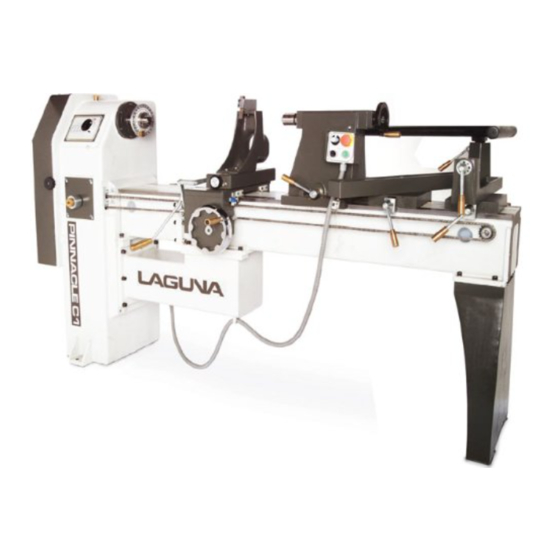
- Page 1 PINNACLE LATHE MTP105 MANUAL LAGUNA TOOLS 2072 Alton Parkway Irvine, California 92606 Ph: 800.234.1976 www.lagunatools.com © 2018, Laguna Tools, Inc. LAGUNA® and the LAGUNA Logo® are the registered trademarks of Laguna Tools, Inc. All rights reserved.
-
Page 3: Table Of Contents
Table of contents Safety Rules Warranty Noise emission Specification sheet Floor plan Receiving your machine Introduction to your machine Where to locate your machine Unpacking your machine Assembly and set up Maintenance Troubleshooting Electrical drawing Spare parts Exploded view drawings and parts lists... -
Page 4: Safety Rules
Safety Rules As with all machinery there are certain hazards involved with the operation and use. Using it with caution will considerably lessen the possibility of personal injury. However, if normal safety precautions are overlooked or ignored, personal injury to the operator may result. If you have any questions relative to the installation and operation, do not use the equipment until you have contacted your supplying distributor. - Page 5 Machines sold through dealers must be registered with Laguna Tools within 30 days of purchase to be covered by this warranty. Laguna Tools guarantees all new machines and accessories sold to be free of manufacturers’...
-
Page 6: Noise Emission
Noise emission Notes concerning noise emission Given that there exists a relationship between noise level and exposure times, it is not precise enough to determine the need for supplementary precautions. The factors affecting the true level of exposure to operators are clearly the amount of time exposed, the characteristics of working environment other sources of dust and noise etc. - Page 7 Tool rest movement Along the bed, full bed length. Adjustable from spindle centre out 13”[330mm]. Tool Rest 10” [254mm] long Tool rest support shaft diameter 1 ½” [38.1mm] Vertical movement 1” [25mm] either side of the lathe centre. Standard supplied accessories Tool Kit Manual Chisel holder...
-
Page 8: Floor Plan
You must then contact the seller [Laguna Tools] as soon as practical. If damage if found after delivery, contact the seller as soon as practical. - Page 9 What you will receive with your machine Bowl tool rest Tool kit Tool holder Rotating centre Levelling screws Copy saddle stops Faceplate Optional router bracket Optional spiral router index plate Drive centre Optional copy follower Knock out rod...
- Page 10 Tool rest Optional spiral cutting gears Optional copy attachment...
- Page 11 Optional spiral gear holder Introduction to the Pinnacle C1 lathe This machine is designed to give you years of safe service. Read this owners manual in its entirety before assembly or use. General description This lathe has been designed to give wood workers the option to customise the lathe to meet their requirements.
-
Page 12: Where To Locate Your Machine
Tool rest Two tool rests are provided. A 10” tool rest that can move to most positions on the lathe bed is provided for normal spindle turning and a second tool rest is provided for large bowl turning. Electrical system The electrical control system is housed in a box that is on an extension cable. -
Page 13: Unpacking Your Machine
Unpacking your machine. To unpack your machine you will need tin snips, knife star screwdriver and a wrench. 1/ Using the tin snips cut the banding that is securing the packing box [If fitted]. WARNING: EXTREAM CAUSION MUST BE USED BECAUSE THE BANDING WILL SPRING AND COULD CAUSE INJURY. -
Page 14: Assembly And Setup
Moving pallet with two pallet jacks If you need to move the lathe around with the top of the box removed you will need to use two pallet jacks as the base will bend if only one is used. It is therefor recommended that you move the lathe to the filal position before you remove the box top. - Page 15 Earth /Ground wire Connecting the electrical supply. The machine is supplied with a plug and socket for connection to the electrical supply. No cable is supplied, as this will depend on your installation. Ensure that your electrical supply matches that of your machine. Connect the ground wire [green or yellow green] as shown.
- Page 16 Spindle locking knob Spindle locking knob unlocked locked To fit the faceplate, lock the spindle by loosening the spindle locking knob and move towards the rear of the lathe. Rotate the spindle until the locking Fitting the face plate shaft locates in one of the indexing holes and tighten the knob.
- Page 17 1/ Loosen the lock nut. 2/ Assemble the saddle onto the bed of the lathe. Ensure that the “V” clamp at the front is engaged with the lathe bed. 3/ Engage the “V” clamp at the rear of the lathe and tighten the lock nut. 4/ You will have to adjust the lock nut Tool rest fitted to lathe so that the clamping handle at the front...
- Page 18 Fitting and removing the tailstock. To remove the tailstock, loosen the clamp handle and slide off the end of the bed. Note the tailstock is made from cast iron and is very heavy. Take care not to drop it or to damage the bed of the lathe when re fitting.
- Page 19 Fitting accessories into the head stock spindle. 1/ Clean the tapered part of the Knock out rod Drive centre accessory and the tapered hole in the spindle. 3/ Firmly push the accessory into the spindle hole. 4/ Try to twist the accessory. It should be locked in position.
- Page 20 Chain guard plate loose 4/ Loosen the chain guard plate and remove. The plate has keyhole slots for easy removal. Chain guard plate removed 5/ Loosen the chain by releasing the chain cam and slide the chain block off. 6/ Pull the chain through the headstock and remove it from the drive dog gear.
- Page 21 1/ Remove the screws that secure the bridge to the lathe bed and the support beside the headstock. Leaving the top screw on both sides of the bridge in place. 2/ Support the bridge and remove the last two screws. 3/ Gently slide the bridge out.
- Page 22 Speed selection Pulley speed chart The lathe is provided with four pulley selections and variable speed. This allows you to select the correct speed for your job and also the correct torque. If you are turning a large bowl blank [48” in diameter] you will not only need to have a low speed but high torque as well.
- Page 23 Electrical controls. Main isolation switch The main electrical controls are located on a movable box. Two locations are provided for the box, one on the headstock and the other on the tailstock. Stop button The main isolation switch is located on Start button the headstock.
- Page 24 Machine test Now is the time to test the machine. 1/ Close the door. If you try to start the machine with the door open the machine will not start, as the safety switch is not made. 2. Check that there are no tools fitted, it is far safer to test the machine with out the tools fitted.
- Page 25 Spindle clamp block not engaged Spindle clamp block engaged Tool holder. The tool holder fits to the bed of the lathe as shown and can be positioned at any suitable position. Tool holder...
- Page 26 Optional copy attachment. Copy bracket Attach the left hand and right hand brackets as shown. Do not fully tighten the bolts. Attach the main bar as shown. Main copy bar Copy bracket Measure from the bed to the top of the main bar at both ends and adjust the brackets untill the main bar is parallel.
- Page 27 Copy cutting tool Assemble the cutting tool as shown There are two methods of adjusting the main bar towards or away from the bed of the lathe. Clamp knob 1/ Rough adjustment is done by loosening the black plastic clamp handle and pushing the bar to the approximate position then.
- Page 28 Master Template Lead in / lead out bracket Clamp screws Fit the template as shown and tighten the clamp screws. Fit a master fit between centers and lock the screw with the lock ring. Once the master or template is in position adjust the lead in / lead out bracket so that the follower has a smooth transition at the ends of the master and the template.
- Page 29 Copy follower To adjust the copy tool, fit the rotating center into Plastic blanking screws the tailstock. Adjust the cutting tip of the tool so that it is level with the point of the rotating center. This will bring the cutting point of the tool onto the centerline of the spindle.
- Page 30 Dust extraction port The tool holder is provided with a dust port that you can attach your dust collector to. It is recommended that the minimum air flow of 1000 cubic feet per minute min and a velocity of 65 feet / min [The stronger the dust collector the better] is connected to the dust port.
- Page 31 5/ Measure the job at both ends and check that it is correct. If you need to adjust the diameter, loosen the template holder bar clamps and adjust with the fine adjustment knobs. Note. When initially setting up, make the job over size as you can always adjust to make it smaller.
- Page 32 Optional flute cutting attachment. Cutting parallel flutes Remove the relevant set of blanking Drill fitted for flute cutting screws from the saddle and store in a safe place. When you remove the bracket, replace the blanking screws; they will keep the tapped holes clean. Attach the drill / router support bracket to the saddle.
- Page 33 When cutting spiral flutes you can only Clamping screw use the spiral indexing plate and never try to use the lathe indexing plate, as this will not allow the spindle to rotate. The spiral cutting indexing plate fits into the Morse taper of the headstock. Clean both the spindle hole and the taper shaft of the indexing plate and push into the head stock spindle hole.
- Page 34 Spiral pitch gear chart Decide on the rotation that you require [Left hand or Right hand] and the pitch that you require. Select the gear set that is required for your job from the gear selection on the inside of the door. Note.
- Page 35 Gears engaged with Note. When assembling the gears they spindle gear must mesh snugly. If they are too loose there will be play in the system, which could cause chatter and a bad surface finish. If they are too tight the system will be difficult to operate.
- Page 36 Spindle break Applying the spindle break block will help remove any backlash in the system and improve the finish of the cut. Do not over tighten as the block is meant to exert light pressure. If you over tighten the block you will not be able to move the saddle along the bed and will be putting extra strain on the system.
- Page 37 Optional rotating steady...
- Page 38 The rotating steady moves with the copy saddle and supports the job close to the copy cutter. The steady has a cutter that will turn the blank prior to the job moving into the steady. This is a useful function as it allows you to turn none round stock. Assembling the optional rotating steady onto the copy saddle Two additional centres are provided.
- Page 39 Turning parallel using the copy saddle. The copy saddle can turn parallel jobs by simply using the slide travel limiter that is a black knob mounted on the front of the saddle. To turn repetitive parallel jobs simply adjust the knob till the sectioned being turned is at the correct diameter.
-
Page 40: Maintenance
Maintenance General. Keep your machine clean. At the end of each day clean the machine. Wood contains moisture and if sawdust or wood chips are not removed they will cause rust. In general we recommend that you only use a Teflon based lubricant on the lathe. - Page 41 Copy saddle “V” guide adjustment. Shaft clamping screw Blocks that are on eccentric cams control the clearance between the bed and the copy saddle. By loosening the shaft clamping screw and rotating the eccentric the clearance is adjusted. It is not recommended that the adjustment be changed unless excessive ware has taken place.
-
Page 42: Troubleshooting
Troubleshooting. Lathe will not start. 1/ Check that the start switch is being pressed full in. 2/ Check that the red emergency / stop switch is fully out. 3/ Check that the electrical power cord is plugged into the power outlet. 4/ Check that the electrical supply is on [reset the breaker]. - Page 43 2/ Damaged drive belt. Replace the belt. 3/ Job is not balanced. Change to slower speed and or balance the job 4/ Damaged pulley. Replace the pulley.
- Page 46 LTL.00.00.00.00 WOOD TURNING LATHE LTL.00.00.00.11 LEVELING BOLT BDS 744-83 NUT М16 LTL.00.00.00.12 TAIL LEG BDS 833-82 SPRING WASHER 2-12Н BDS 2171-83 SCREW М12Х45 LTL.03.00.00.00 BODY DIN 1481 SPRING PIN ø8Х45 TL-4-547 STOPPER ø55 LTL.01.04.00.01 COVER ISO 7380 SCREW М 6Х10 LTL.01.00.00.08 BRACKET BDS 2171-83...
- Page 47 LTL.02.00.00.00 MAIN DRIVING DIN 7991 SCREW М 6Х16 LTL.02.02.00.02 CLAMPING RING LTL.02.02.00.05 SPINDLE BUSHING LTL 02.02.00.01 SPINDLE LTL.02.02.00.06 BIG BUSH RADIAL BEARING WITH BALLS 6210-ZZ LTL.02.02.00.08 MIDDLE BUSH LTL.02.02.00.09 NUT М50x1.5 BDS 3389-62 KEY 10Х8Х56 BDS 2171-83 SCREW М 6Х25...
- Page 48 BDS 833-82 SPRING WASHER 2-6Н LTL.02.02.00.04 SMALL BUSH RADIAL BEARING WITH BALLS 6008-ZZ DIN 7991 SCREW М 6Х10 LTL.02.00.00.06 NUT M30x1.5 LTL.02.00.00.04 PULLEY LTL.02.00.00.08 INDEXING GEAR WHEEL Z=96; m=1.5 VEE BELT XPZ L=1287 BDS 1230-85 BOLT М10Х30 LTL.02.01.02.01 MOTOR PULLEY BDS 2171-83 SCREW М...
- Page 49 LTL.04.01.00.00 TEMPLATE SUPPORT [Optional] CL.00.03.00.28 COTTER LTL.04.01.05.00 FRONT BRACKET BDS 206-78 WASHER AM 8 LTL.04.01.00.29 AXIS DIN 985 NUT M 10 BDS206-78 WASHER AM LTL.04.01.00.09 HANDLE CL.00.03.00.11 SCREW LTL.04.01.01.00 REAR BRACKET BDS 1230-85 BOLT М10Х25 BDS 2171-83 SCREW M 6x20 BDS 833-82 SPRING WASHER 2-6Н...
- Page 50 LTL.04.01.00.04 BEAM LTL.04.01.00.26 STUD LTL.04.01.00.13 STRIP LTL.04.01.00.14 BOTTOM STRIP BDS 2171-83 SCREW M 6x30 CL.00.03.00.22 BOTTOM STRIP LTL.04.01.00.16 BASIC STRIP LTL.04.01.00.24 SAFETY STRIP CL.00.03.00.09 CENTRE DIN 134 WASHER M 8 BDS 2171-83 SCREW M 8x25 BDS 2171-83 SCREW M 6x25 LTL.04.01.00.21 STRIP LTL.04.01.00.12...
- Page 51 [Optional] LTL.04.03.00.00 SUPPORT LTL.04.03.00.02 AXIS BDS 2171-83 SCREW М 8x60 BLOCK DIN 471 RING FOR SHAFT ø12 LTL.04.03.00.05 ECCENTRIC AXIS BDS 833-82 SPRING WASHER 2-8Н DIN 913 STOP SCREW М 8x 8 LTL.04.03.01.00 SUPPORT PLATE WITH PADS LTL.04.03.00.17 SUPPORT BUSHING DIN 134 WASHER M 6 BDS 2171-83...
- Page 52 LTL.04.04.00.00 SUPPORT MECHANISM [Optional] BDS 2171-83 SCREW М10Х90 LTL.04.04.00.21 HANDLE-80-10.5 ISO 7380 SCREW М 6Х20 UN 732 WASHER ø7x ø35x2.5 DIN 439 LOW NUT М 10 CL.01.00.00.22 HANDWHEEL ø200 DIN 1481 SPRING PIN ø5Х30 DIN 471 RING 15 RADIAL BEARING WITH BALLS 6202-2Z LTL.04.04.00.16 REMOTE BUCHING LTL.04.04.00.01...
- Page 53 LTL.05.00.00.00 TAIL STOCK LTL.05.00.00.26 HANDLE-60-M12 LTL.05.00.00.25 TIGHTENING LEVER LTL.05.00.00.24 SPECIAL NUT LTL.05.00.00.23 SUPPORT BUSH LTL.05.00.00.28 TIGHTENING STUD LTL.05.00.00.27 CLAMPING ARM DIN 1481 SPRING PIN ø 8Х50 DIN 439 THIN NUT М12 LTL.05.00.00.01 TAIL STOCK T419 RULER - 0 - 140 mm FOR CL1200 LTL.05.00.00.03 TAIL STOCK BARREL LTL.05.00.00.17...
- Page 54 LTL.07.03.00.00 TOOL REST- MANUAL LTL.07.03.00.01 TOOL REST LTL.07.03.00.02 BASE LTL.07.03.00.03 GUIDE LTL.07.03.00.11 CLAMPING BLOCK LTL.07.03.00.09 FLANGE BDS 2171-84 SCREW М 4Х16 LTL.07.03.00.10 SPECIAL SCREW LTL.05.00.00.25 TIGHTENING LEVER LTL.05.00.00.26 HANDLE-60-M12 LTL.07.03.07.01 BUSH LTL.07.03.00.08 DIN 1481 SPRING PIN LTL.07.03.07.02 WEDGE BLOCK DIN 471 CIR CLIP ø20 LTL.07.03.00.05 ECCENTRIC AXIS...
- Page 55 [Optional] LTL.07.10.00.00 TRAVELING REST LTL.07.10.00.00 TRAVELING REST LTL.07.10.00.05 STEADY REST ISO 7380 SCREW М 10x35 DIN 7349 WASHER М10 LTL.07.10.00.06 STRIP DIN 913 STOP SCREW М 6x 6 LTL.07.10.00.07 STRIP FOR ADJUSTMENT...
- Page 56 ISO 7380 SCREW М6x30 LTL.07.10.00.09 TIGHTENING STUD LTL.07.10.00.08 TIGHTENING STRIP DIN 985 NUT М 10 DIN 1481 SPRING PIN ø 6x30 DIN 125A WASHER M6 ISO 7380 SCREW М8x16 ISO 7380 SCREW М6x20 DIN 1481 SPRING PIN ø 6x16 ISO 7380 SCREW М6x25 LTL.07.10.01.05 BLOCK...
- Page 57 LTL.04.00.00.00 COPYING DEVICE [Optional] LTL.04.04.00.00 SUPPORT MECHANISM LTL.04.05.00.02 ECCENTRIC DIN 471 RING 15 LTL.04.05.00.03 STRETCHING BLOCK BDS 833-82 SPRING WASHER 2-8Н BDS 2171-83 SCREW М 8Х55 CL.01.00.00.34 BRUSH LTL.04.00.00.41 TWIN SUPPORT LTL.04.06.00.00 CONTROL LEVER LTL.04.00.00.19 HANDLE-90-M12 BDS 206-78 WASHER АМ 8...
- Page 58 BDS 2171-83 SCREW М 8Х30 LTL.04.01.00.00 SUPPORT FOR TEMPLATE BDS 744-83 NUT М8 LTL.04.00.00.12 STUD DIN 7991 SCREW М 8Х20 LTL.04.00.00.13 STRIP 6Х20Х135 DIN 985 NUT М 8 DIN 7971C SCREW FOR WOOD 2.9Х13 BDS 2171-83 SCREW М 6Х16 LTL.04.05.00.01 BUSHING LTL.04.00.00.20 TENSION STRIP...
- Page 59 LTL.04.08.00.00 STOP FOR LONGITUDINAL MOVEMENT [Optional] DIN 603 SCREW М6X45 LTL.04.08.01.02 WEDGE LTL04.08.01.03 STRIP LTL.04.08.01.01 STRIP DIN 985 NUT М 6 DIN 315 WING NUT M6 DIN 134 WASHER M 6 LTL.04.08.01.04 STRIP WITH LEFT CHANNEL LTL.04.08.02.04 STRIP WITH RIGHT CHANNEL DIN 7991 SCREW М...
- Page 60 LTL.07.02.00.00 RUNNING CENTRE МК3-Ø50 LTL.07.02.00.03 BODY DIN 471 RING FOR SHAFT Ø17 RADIAL BEARING WITH BALLS 6203-ZZ LTL.07.02.00.02 BUSHING DIN 472 RING FOR OPENING Ø40 LTL.07.02.00.01 CENTRE...
- Page 61 LTL.07.10.03.00 RUNNING CENTRE МК3-Ø20 [Optional] LTL.07.02.00.03 BODY DIN 471 RING FOR SHAFT Ø17 RADIAL BEARING WITH BALLS 6203-ZZ LTL.07.02.00.02 BUSHING DIN 472 RING FOR OPENING Ø40 LTL.07.10.03.01 CENTRE...
- Page 62 LTL.07.05.00.00 STAND FOR CHISELS LTL.07.05.00.01 BASE LTL.07.05.00.02 WEDGE UN 732 WASHER ø7ХФ35Х2.5 DIN 315 WING NUT M6 DIN 603 SCREW М6X35...
- Page 63 OTHER ACCESSORIES LTL. 07.00.00.02 LEVER FOR KNOCK- OUT CL.07.00.00.18 KNIFE FOR EXTERNAL TURNING 16х16 [Optional] CL.07.00.00.12 V- KNIFE LTL.07.00.00.01 LEADING COGWHEEL CENTRE ø40 LTL.07.10.00.10 LEADING COGWHEEL CENTRE ø20 [Optional] LTL.07.01.00.00 FACE PLATE 10''...
- Page 64 LTL.07.04.00.00 PIPE TOOL REST LTL.07.03.00.06 BODY LTL.07.03.07.00 BRACKET LTL.07.03.00.08 COVER LTL.05.00.00.26 HANDLE-60-M12 LTL.05.00.00.25 TIGHTENING LEVER DIN 1481 SPRING PIN ø8Х30 LTL.07.04.00.04 SPECIAL BOLT LTL.07.03.00.05 ECCENTRIC AXIS DIN 471 RING FOR SHAFT ø20 DIN 985 NUT М16 BDS 206-78 WASHER АМ16 LTL.07.03.00.10 SPECIAL SCREW BDS 2171-84...
- Page 65 LTL.06.02.00.00 STAND FOR MILLING MACHINE [Optional] LTL.06.02.01.00 STAND ISO 7380 SCREW М 8Х25 BDS 206-78 WASHER АМ 8 LTL.06.02.04.01 CLAMP BDS 2171-83 SCREW М 8Х45...
- Page 66 LTL.06.01.00.00 SPIRAL MECHANISM [Optional] LTL.06.01.04.04 BUSHING LTL.06.01.04.08 HANDLE LTL.06.01.04.05 INDEXING DISC DIN 471 RING FOR SHAFT ø17 DIN 7991 SCREW М 6Х16 RADIAL BEARING WITH BALLS 6003-ZZ LTL.06.01.04.07 STRIP FOR DEVISION LTL.06.01.04.01 TAPER AXIS LTL.06.01.05.01 BLOCK TO THE BRAKE BDS 833-82 SPRING WASHER 2-8Н...
- Page 67 LTL.06.01.05.03 STRIP BDS 206-78 WASHER АМ10 BDS 1230-85 BOLT М10Х35 DIN 1481 SPRING PIN ø 5Х10 LTL.06.01.03.07 GEAR WHEEL Z= 108; m=1.5 DIN 471 RING 15 LTL.06.01.03.01 GEAR WHEEL Z= 34; m=1.5 LTL.06.01.01.05 STRIP ISO 7380 SCREW М6Х30 LTL.06.01.03.04 GEAR WHEEL Z= 51; m=1.5 DIN 7991 SCREW М...
- Page 68 LIMITED WARRANTY New woodworking machines sold by Laguna Tools carry a one-year warranty effective from the date of shipping. Laguna Tools guarantees all new machine sold to be free of manufacturers’ defective workmanship, parts and materials. We will repair or replace, without charge, any parts determined by Laguna Tools, Inc.
- Page 69 Laguna Tools is not responsible for errors or omissions. Specifications subject to change. Machines may be shown with optional accessories. © 2018, Laguna Tools, Inc. LAGUNA® and the LAGUNA Logo® are the registered trademarks of Laguna Tools, Inc. All rights reserved.
Need help?
Do you have a question about the MTP105 and is the answer not in the manual?
Questions and answers
A friend gave me this machine. My question is the motor ID plate says it is a 3 phase motor but the cord is a 20 amp 3 prong plug. 2 hots and a ground. Is it just a 220 volt single phase machine?