Table of Contents
Advertisement
Quick Links
OPERATOR HANDBOOK
Water-cooled Air Compressor
In any correspondence please quote;
53-56 White House Road IPSWICH ENGLAND IP1 5PB
Telephone: +44 (0) 1473 242000 Fax: +44 (0) 1473 745451 Parts Fax: +44 (0) 1527 838438 Service +44 (0) 1527 838632
For a
5236.2.IA
REAVELL JOB NUMBER:-
CUSTOMER:-
CUSTOMER ORDER NUMBER:-
MACHINE NUMBER:-
PUBLICATION NUMBER:-
ISSUE DATE:-
Gardner Denver Ltd. Reavell House
www.reavell.com
Gardner Denver Ltd
98407.1039 iss8
MARCH 2012
e-mail:- reavellenquiries@gardnerdenver.com
Advertisement
Chapters
Table of Contents

Related Manuals for Gardner Denver Reavell 5236.2.IA


Summary of Contents for Gardner Denver Reavell 5236.2.IA
- Page 1 98407.1039 iss8 ISSUE DATE:- MARCH 2012 Gardner Denver Ltd. Reavell House 53-56 White House Road IPSWICH ENGLAND IP1 5PB Telephone: +44 (0) 1473 242000 Fax: +44 (0) 1473 745451 Parts Fax: +44 (0) 1527 838438 Service +44 (0) 1527 838632 www.reavell.com...
-
Page 3: Table Of Contents
TABLE OF CONTENTS Page 1 OPERATOR HANDBOOK FOR A 2365.2.IA COMPRESSOR TABLE OF CONTENTS SAFETY ............................... 5 OWNERSHIP DATA ..........................6 FOREWORD ............................7 CAUTION .............................. 8 SAFETY PROCEDURES ........................8 ... - Page 4 TABLE OF CONTENTS Page 2 5.11.1 CLASS A – CRITICAL ......................... 25 5.11.2 CLASS B – NON-CRITICAL ......................25 INSTALLATION ............................27 HANDLING OF UNIT .......................... 27 LOCATION ............................27 ...
- Page 5 TABLE OF CONTENTS Page 3 FAULT GUIDE ............................47 11.1 LOW FIRST STAGE PRESSURE ....................47 11.2 1ST STAGE SAFETY VALVE BLOWING AND/OR HIGH FIRST STAGE PRESSURE ....47 11.3 2ND STAGE SAFETY VALVE BLOWING ..................47 ...
- Page 6 TABLE OF CONTENTS Page 4 98407.1039 iss8...
-
Page 7: Safety
SAFETY Page 5 1 SAFETY 5000 SERIES COMPRESSORS WARNING The use of replacement parts or lubricating oils not supplied, recommended or approved by CompAir UK Ltd Ipswich, or the failure to maintain this equipment in accordance with the maintenance instructions, may invalidate the WARRANTY, cause equipment failure, create unsafe or hazardous conditions or result in damage to the equipment. -
Page 8: Ownership Data
SAFETY Page 6 OWNERSHIP DATA TECHNICAL DATA It is recommended that details taken from the compressor and motor nameplates are recorded below. CompAir UK Ltd Ipswich CONTACT DETAILS Contact Name: Sales Telephone: +44 (0) 1473 242000 Address: Notes: CompAir UK Ltd Reavell House 53-56 White House Road Ipswich IP1 5PB... -
Page 9: Foreword
SAFETY Page 7 FOREWORD SPECIAL ATTENTION The STANDARD BUILD of all CompAir UK Ltd (Ipswich Operations) products are not intended for use in either Explosive or Potentially Explosive Atmospheres as defined in Directive 95/9/EC. An Explosive atmosphere is a mixture with air, under atmospheric conditions, of flammable gases, vapours, hazes or dusts in which, after ignition has occurred, combination propagates to the entire unburned mixture and may cause a hazard. -
Page 10: Caution
SAFETY Page 8 CAUTION Use only CompAir UK Ltd Ipswich Genuine Parts when carrying out routine maintenance or repair. The use of replacement parts or lubricating oils not supplied or recommended by CompAir UK Ltd Ipswich can lead to expensive failures, which will not be covered by warranty. Substitution of parts not manufactured or approved by CompAir UK Ltd Ipswich can create a potential personnel hazard. -
Page 11: General
SAFETY Page 9 1.4.1 GENERAL CompAir UK Ltd Ipswich compressor safety relates to the document BS EN1012-1 Compressors and Vacuum Pumps - Safety requirements and the UK Pressure Systems Health & Safety Regulations S.I. No. 128. • Most accidents which occur during the operation and maintenance of machinery result of failure to observe basic safety rules or precautions. -
Page 12: General Safety Precautions
SAFETY Page 10 1.4.3 GENERAL SAFETY PRECAUTIONS • When using cleaning solvents, local Health and Safety Regulations must be complied with. Provide good ventilation and use suitable protection such as a breathing filter mask, safety glass, protective apron and gloves. •... -
Page 13: Maintenance & Repair Precautions
SAFETY Page 11 • Do not open starter compartment to touch electrical components while voltage is applied unless it is necessary for measurement, test or adjustment. Such work should always be carried out by a qualified. Electrician with appropriates tools and protection against an electrical hazard. •... -
Page 14: Precautions In The Event Of Fire
SAFETY Page 12 • Stand clear of all valve covers when removing the securing screws. • When removing valve covers for valve replacement, ensure a minimum of two threads is left engaged on the valve cover securing screws. Lever the valve cover until the 'O' seal is disengaged from the port in the cylinder head. -
Page 15: Amendments
AMENDMENTS Page 13 2 AMENDMENTS ISSUE No. MOD NOTE No. M/C SERIAL No. DATE SECTION NOV 1997 MAY 1999 R005122 Change to Main Bearing Bush/thrust washer AUGUST 2001 Add Studs & Nuts to Service Plans Major Overhaul JULY 2002 Add check condition of crankcase to cylinder studs & 2nd NOV 2002 stage piston rings to 6000 hours service plan. - Page 16 AMENDMENTS Page 14 98407.1039 iss8...
-
Page 17: Logsheet
LOGSHEET Page 15 3 LOGSHEET 98407.1039 iss8... - Page 18 LOGSHEET Page 16 98407.1039 iss8...
-
Page 19: General Description And Operation
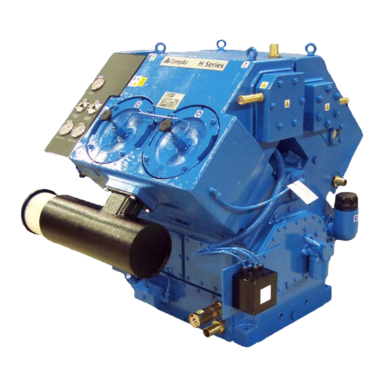
GENERAL DESCRIPTION AND OPERATION Page 17 4 GENERAL DESCRIPTION AND OPERATION Hand Unloaders. Suction Unloader System Gauge Panel Suction Filter Diaphragm Drain Valves Condensate Drainage CONFIGURATION The 5236 Mk2 is a four cylinder, single acting, two stage, 90° vee configuration, water cooled machine. -
Page 20: Synthetic Oils
GENERAL DESCRIPTION AND OPERATION Page 18 SYNTHETIC OILS These are oils which are arrived at by chemical synthesis from petroleum feed stocks, although in some cases they would be from vegetable and mineral oils rather than by straight run distillation of crude. Advantages Carbon deposits are reduced compared with mineral type oils. -
Page 21: Lubrication Schematic Flow Diagram
GENERAL DESCRIPTION AND OPERATION Page 19 LUBRICATION SCHEMATIC FLOW DIAGRAM Cylinders are lubricated by the oil mist created by oil thrown from the big end bearings 25 MICRON PUMP FILTER BY-PASS VALVE RELIEF only opens VALVE when blocked LOW OIL MAIN MAIN PRESSURE... -
Page 22: Cooling
GENERAL DESCRIPTION AND OPERATION Page 20 COOLING Cooling is by water flowing through the jackets and passages, either from the mains or a closed circuit system using a radiator or cooling tower. A bursting disc is fitted to prevent excessive pressure build up in the water spaces if a leak should occur from the coolers. -
Page 23: Condensate Drainage System
GENERAL DESCRIPTION AND OPERATION Page 21 4.10 CONDENSATE DRAINAGE SYSTEM FROM STAGE DELIVERY FROM SEPARATOR DRAIN CONNECTIONS 3 WAY STAGE STAGE SOLENOID VENT VALVE DIAPHRAGM TYPE UNLOADER VALVES DRAIN UNLOADER SURGE VESSEL SAFETY DRAIN VALVE This system comprises a pilot unloader valve, (PUV), and two diaphragm drain valves, (DDV's). The PUV comprises a three way air valve operated by a solenoid in one direction and a combination of air and spring pressure in the opposite direction and is automatically actuated by a signal from the motor starter or a electronic timer. -
Page 24: Suction Unloading
GENERAL DESCRIPTION AND OPERATION Page 22 4.11 SUCTION UNLOADING The unloading of the suction valves during compressor start-up is necessary to reduce starting torque and prevent motor overload. This system comprises a PUV and two first stage suction unloaders. The PUV comprises a three-way air valve operated by a solenoid in one direction and a combination of air and spring pressure in the opposite direction this is automatically actuated by a signal from the starter/control panel. -
Page 25: Leading Particulars
LEADING PARTICULARS Page 23 5 LEADING PARTICULARS UNIT DESIGNATION Model ........................... 5236 Mk.2 TECHNICAL DATA – GENERAL Type..................Four cylinder, 2 stage, vee configuration Cooling ............................Water Direction of rotation, viewed from drive end ..............Anti-clockwise Number of valves ............. One combined suction and delivery per cylinder Type of valve ...................... -
Page 26: Connections
LEADING PARTICULARS Page 24 CONNECTIONS Suction connection ......................... Rp3 Final stage delivery connection ...................... Rp1 Water inlet and outlet connections ....................Rp1 5.10 RUNNING CLEARANCES Description Stage As Fitted (mm) Max Permissible (mm) Piston vertical clearance 0.5/1.2 0.25/1.35 1.35 Piston ring gaps 0.2/0.45 1.43 0.07/0.1... -
Page 27: Torque Wrench Settings
LEADING PARTICULARS Page 25 5.11 TORQUE WRENCH SETTINGS 5.11.1 CLASS A – CRITICAL (All figures ± 5%) NEWTON ASSEMBLY OPERATION SIZE METRE Big End Bearing Bolts First, Second Stage Cylinders to Crankcase First Stage Cooler Cover – Floating End First Stage Cooler Cover – Fixed End Second Stage Cooler Cover –... - Page 28 LEADING PARTICULARS Page 26 98407.1039 iss8...
-
Page 29: Installation
INSTALLATION Page 27 6 INSTALLATION HANDLING OF UNIT When using the compressor and motor eyebolts as the slinging attachment, it is essential that a spreader is used. The lift should always be made vertical, as inclined loadings drastically reduce the eyebolts' strength. Suitable shackles should be used for this operation. LOCATION Compressor should be installed in a cool, level, well ventilated position, clear of fumes, heat or high humidity, to ensure efficient performance and also to prevent temperature problems. -
Page 30: Mounting
INSTALLATION Page 28 Allow sufficient space around the installation to enable safe maintenance working conditions. Protection from severe weather conditions is desirable. Maximum allowable ambient cooling air temperature for radiator cooled sets is dependant on many variables eg, pressure, speed and type of oil. Contact Ipswich Works to ascertain allowable temperature for operating conditions. -
Page 31: Cooling
INSTALLATION Page 29 COOLING Satisfactory compressor operation depends on correct cooling, which requires positive circulation of cool, clean water, free from suspended particles. Check water is flowing in mains installations or, if closed circuit, that radiator is full. It is recommended that a filter be fitted in the inlet water line (mains). Maximum permitted water pressure within the compressor is 5 bar equivalent to 52 metres of water head. -
Page 32: Electrical Connections
INSTALLATION Page 30 ELECTRICAL CONNECTIONS Ensure compressor is installed to comply with local electricity authority stipulations and that necessary electrical work is carried out by a competent electrical engineer. Check electrical requirements for machine with manufacturer before commencing installation wiring. Read "Hazardous Area Operation"... -
Page 33: Commissioning Or Recommissioning
COMMISSIONING OR RECOMMISSIONING Page 31 7 COMMISSIONING OR RECOMMISSIONING W A R N I N G :- BEFORE OPERATING THIS EQUIPMENT USERS SHOULD BE MADE AWARE OF AND ENSURE COMPLIANCE WITH THE HEALTH AND SAFETY REGULATIONS APPROPRIATE TO THIS CLASS OF WORK. -
Page 34: Start-Up Procedure
COMMISSIONING OR RECOMMISSIONING Page 32 START-UP PROCEDURE NOTE: It is not necessary to remove any inhibition lubricant which may have been applied before despatch, unless there are specific instructions attached to the compressor stating otherwise. Screw down fully the first stage suction unloaders. Check radiator is topped up on radiator sets or water is flowing in correct volume in mains water installations. -
Page 35: Operation And Routine Maintenance
OPERATION AND ROUTINE MAINTENANCE Page 33 8 OPERATION AND ROUTINE MAINTENANCE OPERATION AND GENERAL MAINTENANCE The commissioning procedure (Section 4) should be used:– For the first commissioning run; Following overhaul; After standing idle for an extended period. External cleanliness of the compressor pipework and jointing is imperative in order that any leakages may be readily detected. -
Page 36: Stopping
OPERATION AND ROUTINE MAINTENANCE Page 34 STOPPING Stop compressor by depressing stop button on motor control panel. Turn off cooling water flow if no automatic water valve or water pump is fitted. The machine will automatically unload via unloader system. STANDING IDLE The unloaders will automatically be left open. -
Page 37: Maintenance Schedule
MAINTENANCE SCHEDULE Page 35 9 MAINTENANCE SCHEDULE W A R N I N G : 1. BEFORE PROCEEDING WITH MAINTENANCE ON THE COMPRESSOR IT MUST BE STOPPED AND ISOLATED ELECTRICALLY AND MECHANICALLY AND VISIBLE WARNING NOTICES DISPLAYED. 2. IN ADDITION ALL INTERNAL PRESSURE MUST BE RELEASED WITH THE UNIT ISOLATED FROM THE SUPPLY AND STORAGE RESERVOIR AND THE WATER SUPPLY SHUT OFF. -
Page 38: Changing Over From Mineral To Synthetic Lubricant
MAINTENANCE SCHEDULE Page 36 CHANGING OVER FROM MINERAL TO SYNTHETIC LUBRICANT Compressor components in contact with the lubricant should be as clean as is practical before changing over. This is necessitated by the excellent solvency of synthetic oils which tend to loosen and remove existing deposits. -
Page 39: Service Plan
MAINTENANCE SCHEDULE Page 37 SERVICE PLAN Service Kit Number Service Plan - 5236 12 Months From Installation/Last Service Or Task Description Parts Provided Change air intake element Suction filter element (air compressor only) Inspect Belt Tension Inspect Drive Coupling Inspect corrosion rods Replace corrosion rods Corrosion rod assy Remove crankcase doors... - Page 40 MAINTENANCE SCHEDULE Page 38 Service Kit Number Service Plan - 5236 12 Months From Installation/Last Service Or Task Description Parts Provided covers Service 1st stage valves Valve kit Replace 1st stage valves Valve assy Inspect 1st stage pistons Deglaze 1st stage liners Replace 1st stage piston Piston Ring Kit rings...
- Page 41 MAINTENANCE SCHEDULE Page 39 Service Kit Number Service Plan - 5236 12 Months From Installation/Last Service Or Task Description Parts Provided FITT Joint-water pump bracket Joint-water pump Joint-water pump IN/OUT Replace bursting discs ( Bursting discs kit Radiator Set @9000hrs.) Replace drain valve Service kit diaphragm...
- Page 42 MAINTENANCE SCHEDULE Page 40 Service Kit Number Service Plan - 5236 12 Months From Installation/Last Service Or Task Description Parts Provided Test non return valve non return valve Seal 98407.1039 iss8...
-
Page 43: Dismantling And Reassembly Of Valves
DISMANTLING AND REASSEMBLY OF VALVES Page 41 10 DISMANTLING AND REASSEMBLY OF VALVES 10.1 GENERAL Keep a spare oiled and maintained set of valves in store for quick compressor servicing. Valves should have a thin carbon layer and be slightly moist with oil. Valve removal is a simple procedure but the following guidelines should be observed. -
Page 44: First Stage Valves - With Suction Unloaders
DISMANTLING AND REASSEMBLY OF VALVES Page 42 10.3 FIRST STAGE VALVES – WITH SUCTION UNLOADERS 10.3.1 REMOVAL Remove the first stage suction unloader pipework and the nuts securing each of the two valve covers and withdraw the covers from the locating studs using forcing screws in the tapped holes provided in each cover. - Page 45 DISMANTLING AND REASSEMBLY OF VALVES Page 43 Automatic unloader 1st STAGE CONCENTRIC VALVE Note: Valve is shown inverted for ease of assembly 98407.1039 iss8...
-
Page 46: First Stage Valves - Without Suction Unloaders
DISMANTLING AND REASSEMBLY OF VALVES Page 44 10.4 FIRST STAGE VALVES – WITHOUT SUCTION UNLOADERS 10.4.1 REMOVAL Remove the nuts securing each of the two valve covers from the locating studs using forcing screws in the tapped holes provided in each cover. Screw valve lifters to each valve and lift from the cylinders. -
Page 47: Second Stage Valves
DISMANTLING AND REASSEMBLY OF VALVES Page 45 10.5 SECOND STAGE VALVES 10.5.1 REMOVAL As 7.3 A. i) except for removal of suction unloader pipework. 10.5.2 DISMANTLING Remove and discard 'O' ring (7). Unscrew and remove nut (8) whilst holding the valve in a soft jawed vice with just sufficient force to prevent it from turning. - Page 48 DISMANTLING AND REASSEMBLY OF VALVES Page 46 2nd STAGE CONCENTRIC VALVE Note: Valve is shown inverted for ease assembly 98407.1039 iss8...
-
Page 49: Fault Guide
FAULT GUIDE Page 47 11 FAULT GUIDE W A R N I N G :- BEFORE PROCEEDING WITH MAINTENANCE ON THE COMPRESSOR IT MUST BE STOPPED AND ISOLATED ELECTRICALLY AND MECHANICALLY AND VISIBLE WARNING NOTICES DISPLAYED. IN ADDITION ALL INTERNAL PRESSURE MUST BE RELEASED WITH THE UNIT ISOLATED FROM THE STORAGE RESERVOIR AND THE WATER SUPPLY SHUT OFF. -
Page 50: Compressor Runs Longer To Achieve System Pressure
FAULT GUIDE Page 48 Fault Probable Cause Recommendation(s) Check LOW FIRST STAGE 11.4 COMPRESSOR PRESSURE symptoms. RUNS LONGER TO Piston ring wear. Check components, renew rings and ACHIEVE SYSTEM liners on 1st and 2nd stages as necessary. Check blowby on crankcase PRESSURE breather pipe. -
Page 51: Illustrated Parts List
ILLUSTRATED PARTS LIST Page 49 12 ILLUSTRATED PARTS LIST CONTENTS PAGE CRANKCASE ................A RUNNING GEAR ................. B 1st STAGE CYLINDERS ............. C 2nd STAGE CYLINDERS ............D 1st STAGE COOLER ..............E 2nd STAGE COOLER ..............F LUBRICATION ................G UNLOADERS ................ -
Page 52: Crankcase
ILLUSTRATED PARTS LIST Page 50 * Thrust Washers fitted to older machines are now obsolete. If a replacement part is required a new type main bearing bush may be supplied. New compressors hav new type main bearing bush fitted with integral thrust washer. -
Page 53: Crankcase
ILLUSTRATED PARTS LIST Page 51 12.1 CRANKCASE PARTS ASSEMBLIES ASSY No PER PARTS DESCRIPTION COMPRISING OF ITEMS MACHINE ASSEMBLY No CRANKCASE ASSEMBLY A1, 2, 3, 4, 5, 6, 27, 28 & 32 A30051.50 BEARING HOUSING ASSEMBLY A13, 14, 15, 16*, & 17 E60010.50 BEARING HOUSING ASSEMBLY A18, 19*, 20, 21, 22, &... -
Page 54: Running Gear
ILLUSTRATED PARTS LIST Page 52 14 12 15 RUNNING GEAR 98407.1039 iss8... -
Page 55: Running Gear
ILLUSTRATED PARTS LIST Page 53 12.2 RUNNING GEAR PARTS ASSEMBLIES ASSY No PER PARTS DESCRIPTION COMPRISING OF ITEMS MACHINE ASSEMBLY No CONN-ROD ASSEMBLY B1, 2, 3 & 4 U.270.A PISTON ASSEMBLY B6, 7, 8, 9 & 10 D66376.50 PISTON RING SET B9 &... -
Page 56: 1St Stage Cylinders
ILLUSTRATED PARTS LIST Page 54 10 9 8 7 6 5 4 3 2 1 1st STAGE CYLINDERS 98407.1039 iss8... -
Page 57: 1St Stage Cylinders
ILLUSTRATED PARTS LIST Page 55 12.3 1ST STAGE CYLINDERS PARTS ASSEMBLIES ASSY No PER PARTS DESCRIPTION COMPRISING OF ITEMS MACHINE ASSEMBLY No CYLINDER & COOLER BODY ASSY C1, 2, 3, 4, 5, 6, 7, 8, 9, 10, 21, & 22 A30053.50 VALVE COVER ASSEMBLY C19 &... -
Page 58: 2Nd Stage Cylinders
ILLUSTRATED PARTS LIST Page 56 21 20 19 18 17 16 15 14 13 12 11 10 9 8 7 6 5 4 3 2 1 2nd STAGE CYLINDERS 98407.1039 iss8... -
Page 59: 2Nd Stage Cylinders
ILLUSTRATED PARTS LIST Page 57 12.4 2ND STAGE CYLINDERS PARTS ASSEMBLIES ASSY No PER PARTS ASSEMBLY No DESCRIPTION MACHIN COMPRISING OF ITEMS CYLINDER & COOLER BODY ASSY D1, 2, 3, 4, 5, 6, 7, 8, 9, 10, 11& 12 A30052.50 VALVE COVER ASSEMBLY D26, 27 &... -
Page 60: 1St Stage Cooler
ILLUSTRATED PARTS LIST Page 58 13 12 11 10 9 8 7 6 5 1st STAGE COOLER 98407.1039 iss8... -
Page 61: 1St Stage Cooler
ILLUSTRATED PARTS LIST Page 59 12.5 1ST STAGE COOLER PARTS ASSEMBLIES ASSY No PER PARTS DESCRIPTION COMPRISING OF ITEMS MACHINE ASSEMBLY No TUBESTACK ASSEMBLY E5, 6, 7, 8, 9, 10, 11, 12 & 13. D100619.100 COOLER COVER/SEPARATOR ASSY E3 & E4 E60659.50 INDIVIDUAL PARTS ITEM... -
Page 62: 2Nd Stage Cooler
ILLUSTRATED PARTS LIST Page 60 10 11 12 13 14 15 16 17 18 19 20 21 6 5 4 3 2 1 9 8 7 2nd STAGE COOLER 98407.1039 iss8... -
Page 63: 2Nd Stage Cooler
ILLUSTRATED PARTS LIST Page 61 12.6 2ND STAGE COOLER PARTS ASSEMBLY ASSY No PER PARTS DESCRIPTION COMPRISING OF ITEMS MACHINE ASSEMBLY No TUBESTACK ASSEMBLY F10, 11, 12, 13, 14, 15, 16, 17, & 18. NON RETURN VALVE ASSEMBLY F22, 23, 24 & 25 INDIVIDUAL PARTS ITEM ASSEMBLY... -
Page 64: Lubrication
ILLUSTRATED PARTS LIST Page 62 4 5 6 To 1 stage suction LUBRICATION 98407.1039 iss8... -
Page 65: Lubrication
ILLUSTRATED PARTS LIST Page 63 12.7 LUBRICATION PARTS ASSEMBLIES ASSY No PER PARTS DESCRIPTION COMPRISING OF ITEMS MACHINE ASSEMBLY No OIL PUMP DRIVE ASSEMBLY G7, 8 & 9 C85737.3 INDIVIDUAL PARTS ITEM ASSEMBLY DESCRIPTION No OFF PART No PLUG PS1068.2 SEAL 98660.1153 95502.366... -
Page 66: Unloaders
ILLUSTRATED PARTS LIST Page 64 To 1 stage seperator 12 13 14 15 To 1 stage seperator UNLOADERS 98407.1039 iss8... -
Page 67: Unloaders
ILLUSTRATED PARTS LIST Page 65 12.8 UNLOADERS INDIVIDUAL PARTS ITEM ASSEMBLY DESCRIPTION No OFF PART No 95000.256 SETSCREW RELIEF VALVE 98650.1011 SEAL 98660.1157 95111.5 STUD D66720.8.102 U334-L DIAPHRAGM DRAIN VALVE PLUG 98156.2560 NIPPLE 95414.165 SEAL 98504.1143 SEAL 98660.1156 95405.97 ELBOW DRAIN PIPE ASSEMBLY - 1st Stage D100973.3 JOINT... -
Page 68: External Components
ILLUSTRATED PARTS LIST Page 66 EXTERNAL COMPONENTS 98407.1039 iss8... -
Page 69: External Components
ILLUSTRATED PARTS LIST Page 67 12.9 EXTERNAL COMPONENTS INDIVIDUAL PARTS ITEM ASSEMBLY DESCRIPTION No OFF PART No 95000.312 SETSCREW JOINT PS1813.20 SUCTION FILTER SILENCER 98262.1010 SUCTION FILTER SILENCER ELEMENT 98262.1063 PRESSURE GAUGE - 2ND STAGE 98288.1027 98288.1026 PRESSURE GAUGE - 1ST STAGE THERMOMETER FINAL DELIVERY 98288.1085 THERMOMETER 1ST STAGE... -
Page 70: Typical Drive Arrangements
ILLUSTRATED PARTS LIST Page 68 To motor Direct Drive Belt Drive TYPICAL DRIVE ARRANGEMENTS 98407.1039 iss8... -
Page 71: Typical Drive Arrangements
ILLUSTRATED PARTS LIST Page 69 12.10 TYPICAL DRIVE ARRANGEMENTS INDIVIDUAL PARTS ITEM ASSEMBLY DESCRIPTION No OFF PART No C200716 BELT DRIVE C86469 MOTOR PLATES C86470.1 ADJUSTING BLOCKS ADJUSTING SCREWS D66720.16.20 E60017 STUD M16 X 36 E.60249 MOTOR BRACKET E60253 PULLEY PS1130.21 BELT GUARD 95000.260... -
Page 72: 1St Stage Concentric Valve
ILLUSTRATED PARTS LIST Page 70 Note: Valve is shown inverted for ease of assembly 1ST STAGE CONCENTRIC VALVE 98407.1039 iss8... -
Page 73: 1St Stage Concentric Valve
ILLUSTRATED PARTS LIST Page 71 12.11 1ST STAGE CONCENTRIC VALVE (AUTOMATIC UNLOADER VERSION) INDIVIDUAL PARTS ITEM ASSEMBLY DESCRIPTION No OFF PART No CONCENTRIC VALVE COMPLETE 98650.1520 L1/1 LOWER BODY (including stud) L1/2 VALVE PLATE L1/3 VALVE SPRING L1/4 VALVE SPRING LIFT WASHER - Lower (0.8mm) L1/5 L1/6... -
Page 74: 2Nd Stage Concentric Valve
ILLUSTRATED PARTS LIST Page 72 Note: Valve is shown inverted for ease of assembly 2ND STAGE CONCENTRIC VALVE 98407.1039 iss8... -
Page 75: 2Nd Stage Concentric Valve
ILLUSTRATED PARTS LIST Page 73 12.12 2ND STAGE CONCENTRIC VALVE INDIVIDUAL PARTS ITEM ASSEMBLY DESCRIPTION No OFF PART No 98650.1039 CONCENTRIC VALVE COMPLETE LOWER BODY (including stud) VALVE/BACKING PLATE SPRING PLATE SPRING PLATE VALVE PLATE 'O' RING 95602.55 RA,RC,RD UPPER BODY 98407.1039 iss8... -
Page 76: Diaphragm Drain Valve
ILLUSTRATED PARTS LIST Page 74 DIAPHRAGM DRAIN VALVE 98407.1039 iss8... -
Page 77: Diaphragm Drain Valve
ILLUSTRATED PARTS LIST Page 75 12.13 DIAPHRAGM DRAIN VALVE PARTS ASSEMBLIES ASSY No PER PARTS DESCRIPTION COMPRISING OF ITEMS MACHINE ASSEMBLY No MAINTENANCE KIT - 1st and 2nd N3, 5, 6, 7, 11 & 12 98650.1531 stage Diaphragm Valve SERVICE KIT - 1st and 2nd stage N4 &... -
Page 78: Control System
ILLUSTRATED PARTS LIST Page 76 To 2 Stage Cylinder Condensate Drain Connection SUCTION UNLOADER STAGE STAGE PRESS PRESS PRESS GAUGE GAUGE GAUGE To 2 Stage Cylinder Condensate Drain Connection To 1 Stage To 2 Stage Separator Separator Pressure Pressure Connection Connection To Crankcase Oil Pressure... -
Page 79: Control System
ILLUSTRATED PARTS LIST Page 77 12.14 CONTROL SYSTEM INDIVIDUAL PARTS ITEM ASSEMBLY DESCRIPTION No OFF PART No C202283 BRACKET SETSCREW 95000.227 CAPSCREW 95018.132 PILOT UNLOADING VALVE PS2197 95410/264 C73732/7 PLUG WASHER 98660/1153 98524/1042 LOW OIL PRESSURE SWITCH CAPSCREW 95018.100 P10# SUCTION UNLOADING VALVE 98650.1658 OIL SERVICES PIPE... - Page 80 ILLUSTRATED PARTS LIST Page 78 98407.1039 iss8...
-
Page 81: Ancillary Equipment
ANCILLARY EQUIPMENT Page 79 13 ANCILLARY EQUIPMENT 13.1 VEE BELT ADJUSTMENT & TENSIONING – APP011 DRIVE RECOMMENDATIONS (V-BELT TRANSMISSION) Details of drive arrangements and non isolation pad mountings are available from Reavell Works, Ipswich. An overload device must always be fitted to motors. Manufacturers terminal box wiring instructions must be observed. - Page 82 ANCILLARY EQUIPMENT Page 80 BELT DEFLECTION MEASUREMENT Required Deflection Force "P" at Centre of Span For Compressor Speed Ranges (Newtons) Above follows current BS3790 practice. RECOMMENDED TENSIONING FORCE Centre Distance Belt tension indicator applied to mid-span Straight edge ADJUSTMENT METHOD If belt tension is incorrect, release the compressor holding down screws enough to allow the adjustment screws to be free to slide the compressor on its adjustment slots without being too loose.
- Page 83 ANCILLARY EQUIPMENT Page 81 TABLE Belt Force required to deflect belt 16 mm per metre of span Section Small Pulley Newton Kilogram force Ø mm (kgf) 67 to 95 10 to 15 1.0 to 1.5 100 to 140 15 to 20 1.5 to 2.0 100 to 132 20 to 27...
-
Page 84: Direct Drive - App011B
ANCILLARY EQUIPMENT Page 82 13.2 DIRECT DRIVE – APP011B DIRECT DRIVE: Ensure compressor and drive motor is correctly aligned as the flexible couplings are for vibration duties only and not as non-alignment couplings. Note direct coupled sets with bell type housing (see below) are self aligning. -
Page 85: Radiator Filling Water Cooling System - App077
ANCILLARY EQUIPMENT Page 83 13.3 RADIATOR FILLING WATER COOLING SYSTEM – APP077 TYPICAL RADIATOR WATER COOLING SYSTEM SPECIAL INSTRUCTIONS FOR STARTING COMPRESSOR COOLANT (ANTI-FREEZE) FILLER CAP COOLING WATER PIPE OUTLET RADIATOR DRAIN WATER PUMP COOLING WATER PIPE INLET COOLING WATER PIPE RETURN BEFORE INITIAL STARTING FILLING AND BLEEDING THE WATER SYSTEM. -
Page 86: Water Pump Assembly & Drive - App073
ANCILLARY EQUIPMENT Page 84 13.4 WATER PUMP ASSEMBLY & DRIVE – APP073 WATER PUMP DRIVE 5236, 5336, 5436 MK2, 5436.3 & 5437.1 Item No Part No Description No Off C201503 Gasket water pump C201504 Gasket water pump C201537 Sprocket water pump drive C201538 Gasket water pump bracket C201809... -
Page 87: Pressure Maintaining Valve - App057
ANCILLARY EQUIPMENT Page 85 13.5 PRESSURE MAINTAINING VALVE – APP057 PRESSURE MAINTAINING VALVE (BACK PRESSURE REGULATING VALVE) 98650.1759 Maximum Pressure 40 bar Temperature Range - 10 to 100°C Flow Rate 300m³/hr Connections 1" BSPP This valve is fitted to maintain a back pressure through the separators, filters and the dryers (if fitted). This ensures that these items of equipment reach their optimum working pressure as soon as possible, to give long filter life, good oil separation and low oil consumption. -
Page 88: Solenoid Valves - App138
ANCILLARY EQUIPMENT Page 86 13.6 SOLENOID VALVES – APP138 3 WAY SOLENOID VALVE PS2197 OPERATION 3 way normally closed energise to open, continuous duty. On starting the solenoid valve opens (energised) this operates the diaphragms which in turn closes the valves within the D.D.Vs. -
Page 89: Safety Valve - App167
ANCILLARY EQUIPMENT Page 87 13.7 SAFETY VALVE – APP167 Installation and Operating Instructions SAFETY VALVES INTRODUCTION Due consideration should be taken of climatic. Process or other conditions which might adversely affect the performance of the safety valve. Installation must be undertaken by qualified technicians and to good engineering practice. - Page 90 ANCILLARY EQUIPMENT Page 88 FUNCTIONAL TESTING Once installed in service. Valves should be tested at least once every six months to ensure free movement of parts. This should be carried out by operating the easing gear when the valve is under a pressure of not less than 75'% of the set pressure.
-
Page 91: Temperature Controller - App090C
ANCILLARY EQUIPMENT Page 89 13.8 TEMPERATURE CONTROLLER – APP090C THERMOMETER SWITCHES C202556, C202749, C202960 & C202964 98288.1093, 98288.1094 & 98288.1215 THESE THERMOMETER SWITCHES ARE SET TO THE FIGURES QUOTED BELOW, THE FOLLOWING INFORMATION IS FOR SETTING INFORMATION ONLY, IF THE TEMPERATURE SWITCH HAS TO BE REPLACED OR RE-ADJUSTED. - Page 92 ANCILLARY EQUIPMENT Page 90 CONTROLLER TRIP POINTER USED ON PART No STOP SETTING °C COMPRESSOR MODEL C202556.1 5236.1 C202556.2 5212 C202556.3 5336,5415 C202556.4 5215 & 5217 C202556.5 5236.2,5315 C202556.6 5415E5317,5417.5417N C202556.7 5436(CU TUBES) C202556.8 5436.1 &.2,5436H,5436N,5436SN & 5437 C202749.1 5280 C202749.2 5280 C202749.3...
-
Page 93: Pressure Gauge - App070
ANCILLARY EQUIPMENT Page 91 13.9 PRESSURE GAUGE – APP070 PRESSURE GAUGES GENERAL The pressure gauge should be installed such as to avoid exposure to heat and vibration and to enable easy observation of the dial indication. IMPORTANT It is common practise to install the pressure gauge without an isolating device, so to facilitate calibration or replacement the system must be de pressurised before any work is carried out. -
Page 94: Pressure Switch - App086 & 088
ANCILLARY EQUIPMENT Page 92 13.10 PRESSURE SWITCH – APP086 & 088 HIGH AIR/GAS PRESSURE SWITCHES PART NO: 98524/1025, 1049, 1094, 1095, 1096, 1102, 1103, 1104, 1107, 1128, 1135, 1136, 1137, 1210 & 1212 OPERATION - MANUAL START/AUTO STOP Located as close as possible to the delivery, inlet air/gas line, the pressure switch stops the compressor when the air/gas pressure rises or falls above or below the pre-set pressure setting. - Page 95 ANCILLARY EQUIPMENT Page 93 ADJUSTING NUT CONDUIT THREAD INSTALLATION Mount the switch by the bracket provided. It is usual to connect 1 (C) and 2 (NC) to the compressor electrical control circuit terminals marked "Pressure Switch". Remove cover to set pressure setting, using a pressure gauge. Note:- Switches are pre-set and do not usually need adjusting.
- Page 96 ANCILLARY EQUIPMENT Page 94 LOW OIL PRESSURE SWITCH PART NO: 98524.1042, 98524.1122, 98524.1140 & 98524.1170 OPERATION Located in the crankcase on water-cooled & large air-cooled compressors, in the oil filter body on air-cooled, the pressure switch stops the compressor when the oil pressure drops to pre-set pressure setting. PART NO.
-
Page 97: Anti-Vibration Mounts - App003
ANCILLARY EQUIPMENT Page 95 13.11 ANTI-VIBRATION MOUNTS – APP003 AVA TYPE PART NUMBERS VARIOUS PREVENTIVE MAINTENANCE After installation and initial running in. Record height dimension (H) of each mount. After a week or 100 hours running time recheck and record dimension (H) Check this dimension every 3 to 6 months depending on usage i.e. -
Page 98: Demister - App043
ANCILLARY EQUIPMENT Page 96 13.12 DEMISTER – APP043 OIL/MOISTURE DEMISTER VESSELS TYPICAL ARRANGEMENT GENERAL DESCRIPTION These Demister Vessels are designed to separate condensate from the compressor drainage blowdown system, discharging clean air through coalescer filters to the atmosphere. The discharge air contains less than 0.5-mg/M³-oil mist with a noise level hardly above the compressor noise. - Page 99 ANCILLARY EQUIPMENT Page 97 DEMISTER VESSELS PARTS Item No. Description E61201 E61187 E61198 E61106 Used on 5215/5217 5315/5317 5280/5336 5436N/5437N 5236 5415/5417/5420 5436/5437 5417N/5420N Demister Tank E61200 E61188 E61197 E61105 Dowty Seal PS1322.8 PS1322.8 PS1322.8 PS1322.8 Cable PS1481 PS1481 PS1481 PS1481 Bend 95405.184...
-
Page 100: Water Inlet Control Valve - App071 & 704
ANCILLARY EQUIPMENT Page 98 13.13 WATER INLET CONTROL VALVE – APP071 & 704 WATER VALVE NORMALLY CLOSED U231.F & U231.H OPERATION Located on the water inlet to the compressor the valve stops water flowing through the compressor on shut down. This is achieved by means of a diaphragm-operated valve piped to the compressor LP pressure, on shut down the air pressure is released from the diaphragm thus closing the valve. - Page 101 ANCILLARY EQUIPMENT Page 99 MAINTENANCE AND SPARES KITS Part Number Description Makers Part Number Used on Stem & Disc Kit 97701319 98405.1004 Stuffing Box & Nut Kit 97701320 98650.1291 Diaphragm Kit 97700017 Stem & Disc Kit 97701321 98650.1292 98504.1005 Stuffing Box & Nut Kit 97701320 U231.F Diaphragm Kit...
- Page 102 ANCILLARY EQUIPMENT Page 100 WATER VALVE NORMALLY OPEN 98650.1298 IF FITTED OPERATION Located on the water inlet to the compressor this valve is often used as a by pass valve when compressors are operating in tandem and using the same water supply i.e. a normally closed and normally open valve fitted.
- Page 103 ANCILLARY EQUIPMENT Page 101 APP704 PNEUMATIC WATER VALVE COMPAIR PART NUMBERS: PORT SIZE BODY MATERIAL 98650.2584.1 1” BSP BRONZE 98650.2584.2 1” BSP STAINLESS STEEL 98650.2585.1 ¾” BSP BRONZE 98650.2585.2 ¾” BSP STAINLESS STEEL DESCRIPTION A 2-port pneumatically actuated on/off valve for use on water, air, oil and gasses.
- Page 104 ANCILLARY EQUIPMENT Page 102 98407.1039 iss8...
-
Page 105: Standard Wiring Terminal Numbers
STANDARD WIRING TERMINAL NUMBERS Page 103 14 STANDARD WIRING TERMINAL NUMBERS WHEN THE MOTOR AND / OR STANDARD COMPRESSOR CONTROL DEVICES HAVE BEEN PRE- WIRED INTO LOCAL MARSHALLING BOXES OR DIRECTLY INTO A STARTER / CONTROL PANEL, THE FOLLOWING TERMINAL NUMBERS ARE USED. ALL OTHER TERMINALS ARE AS SPECIFIC CONTRACT DRAWINGS STANDARD TERMINAL IDENTIFICATION FOR SET WIRING TERMINAL... - Page 106 STANDARD WIRING TERMINAL NUMBERS Page 104 98407.1039 iss8...
- Page 108 WARNING The use of replacement parts or lubricating oils not supplied, recommended or approved by Reavell, may lead to failure in service which would not be covered by the warranty. Any unauthorised modifications or failures to maintain this equipment is accordance with the manufacturer’s maintenance instructions may make it unsafe.
Need help?
Do you have a question about the Reavell 5236.2.IA and is the answer not in the manual?
Questions and answers