Gardner Denver L Series Original User And Service Manual

Gardner Denver L Series Original User And Service Manual

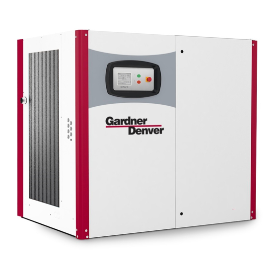
Frame 5 base mounted compressor
Hide thumbs Also See for L Series:
Table of Contents

Advertisement

L-SERIES FRAME 5
BASE MOUNTED COMPRESSOR
Original User and Service Manual
125, 150, 180 HP
MODELS:
L90-132E
LRS90-132E
50/60Hz
13-25-639
Version 00
September, 2019

Advertisement

Table of Contents
loading

Summary of Contents for Gardner Denver L Series

  • Page 1 L-SERIES FRAME 5 BASE MOUNTED COMPRESSOR Original User and Service Manual 125, 150, 180 HP MODELS: L90-132E LRS90-132E 50/60Hz 13-25-639 Version 00 September, 2019...
  • Page 2 Gardner Denver parts will be used. Warranty The conditions of the Gardner Denver Warranty are set out in the company's standard Conditions of Sale available from the Distributor supplying the machine.
  • Page 3: Warning -Prohibition - Mandatory Label Information

    Gardner Denver Rotary Screw compressors are the result of advanced engineering and skilled manufacturing. To be assured of receiving maximum service from this machine, the owner must exercise care in its operation and maintenance. This book is written to give the operator and maintenance department essential information for day-to-day operation, maintenance and adjustment.
  • Page 4 Check and, if required, re-tighten connection terminals. Check the DC bus voltage at the system terminal strip of For further details, see the operating instructions. the frequency converter by measuring this between the Danger of electric shock from loaded +DC and -DC terminals (the exact position can be found condensers! Please always first in the supplied operating manual of the frequency disconnect the system from the power...
  • Page 5 NOTICE Indicates a property damage message. PROHIBITION/MANDATORY ACTION REQUIREMENTS Asphyxiation Hazard – Never breathe in compressed air Never operate the unit with open doors or loose access from this system. panels. Read the operator’s manual before proceeding with this Opening pressure relief valve = xx bar (value "xx" see task sticker on compressor) Handle package at forklift points only...
  • Page 6: Preface

    Fig. 1 Your Gardner Denver distributor Name: Address: Telephone: Fax: Contact: Spare Parts: Service: 13-25-639 v00 Page 5...
  • Page 7: Compressor Information

    Therefore, it is essential that the prescribed Gardner Denver will not guarantee the safe operation of maintenance intervals are adhered to and that the machine/equipment if it is not handled in a way...
  • Page 8 Gardner Denver replacement parts  alterations to the equipment. The warrantee or liability terms of Gardner Denver’s Terms and Conditions are not expanded by the foregoing. Any independent alterations to the compressor equipment/station or installing components which have not been approved by the manufacturer (e.g.,...
  • Page 9: Table Of Contents

    1 Warning -Prohibition - Mandatory Label Information ..................2 2 Preface .................................. 5 Compressor Information ..........................6 Intended Use ............................... 6 Maintenance and Care ..........................6 Notes ................................6 3 Table of contents ..............................8 4 Safety regulations .............................. 10 General safety regulations .........................
  • Page 10 10 Service and maintenance ........................... 41 10.1 Maintenance recommendations ........................ 41 10.2 Maintenance Electric Motor ........................41 10.2.1 Motor Lubrication ........................... 41 10.3 Maintenance and inspection schedule ....................... 42 10.3.1 Service Check List ..........................43 10.4 Oil change ..............................45 10.5 Change oil filter cartridge...........................
  • Page 11: Safety Regulations

    General safety regulations Danger Safety measure required Working with compressors involves Everyone working with the machine must have first read and understood the operating manual. Don’t leave this until you start work – it’s too late. dangers that are not immediately apparent.
  • Page 12: Particular Dangers Associated With Compressed Air

    4.2 Particular dangers associated with compressed air Danger Safety measure required Compressed air is very powerful. It can Never play about with compressed air. be used for example to break open concrete but can also put lives at risk. Small parts propelled at high speed by When using compressed air to clean equipment, work with extreme caution compressed air can penetrate the skin and always wear suitable eye protection.
  • Page 13 Danger Safety measure required Compression results in high The system should be set up such that hazardous mixtures (inflammable temperatures. Risk of explosion from solvent vapors etc. but also dusts and other dangerous or toxic materials) drawn in materials. cannot be drawn in. The same applies to flying sparks. Never use the machine in environments where the possibility cannot be ruled out that inflammable or toxic vapors may be taken in.
  • Page 14: Particular Dangers Associated With Machines

    4.3 Particular dangers associated with machines Danger Safety measure required Risk of electric shock. Electrical connections must meet the local regulations. Power units must be connected to earth and protected from short-circuits by means of fuses. Insufficient power quality could have Always check a correct power supply to the compressor before commissioning.
  • Page 15: Particular Dangers Associated With Water-Cooled Units

    4.4 Particular dangers associated with water-cooled units Danger Safety measure required If open cooling towers are used in the The growth and spread of bacteria must be prevented by corresponding service cooling water circuit, it is possible for and water treatment methods. legionella (Legionella pneumophila) and other bacteria to grow and spread.
  • Page 16: General Workplace Dangers

    4.6 General workplace dangers Danger Safety measure required This manual only describes how to work Please note and pass on general statutory and other binding regulations that safely with the compressor itself. But may supplement the operating manual for the prevention of accidents and the other dangers will arise during work.
  • Page 17: Dangers During Maintenance And Repairs

    Contact your Gardner Denver agent. removed. If you maintain the compressor and have not been trained by Gardner Denver, you will put yourself and others at risk. Incorrectly configured spare parts may Spare parts must meet the technical requirements laid down by the jeopardize safety, e.g., tear when...
  • Page 18 Danger Safety measure required During the course of maintenance and Never weld any pressure reservoir or change it in any way. repairs, parts can be damaged which If work which produces heat, flames, or sparks has to be carried out on a are important for safety.
  • Page 19: Dangers Resulting From Conversion Work/Modifications On The Machine

    4.9 Dangers resulting from conversion work/modifications on the machine Danger Safety measure required Genuine parts are designed especially No alterations, additions, or modifications to the machine may be carried out without the approval of the manufacturer. Unauthorized modifications to the for the machine.
  • Page 20: Design And Functioning

    Design of the unit 5.1.1 Design of air-cooled units Fig. 2 13 Minimum pressure and 24 Feed cable entry 1 Intake filter non-return valve 25 Final compression temperature 2 Suction regulator 14 Air cooler sensor 3 Electric motor 15 Fine oil separator extraction 26 System pressure sensor 4 Screw compressor 16 Oil temperature regulator...
  • Page 21: Design Of Water-Cooled Units

    5.1.2 Design of water-cooled units Fig. 3 1 Intake filter 16 Oil temperature regulator 31 Heat-recovery connection (option) 2 Suction regulator 17 Cooling fan 32. Cooling water inlet (only water- 3 Electric motor 18 Cool air inlet filter pad cooled units) 4 Screw compressor 19 Compressed air outlet 33.
  • Page 22: System Schematic

    System Schematic Fig. 4 Intake filter 12 Minimum pressure and non- 27 Choke valve Suction regulator return valve 28 Intake monitor, visual 2.1 Actuator 13 Network pressure sensor 29 Intake filter monitor (S7) *) 2.2 Throttle valve 14 Air cooler 30 Fine separator monitor (S6) *) 2.3 Check valve 15 Oil cooler...
  • Page 23: Oil Circuit

    Oil circuit System control The oil flows from the pressure reservoir (- 6 -) into the (See also operating instructions for the compressor oil thermostat (- 16 -). With oil temperatures < 131 °F controller) the oil flows via the by-pass of the oil cooler directly into the oil filter (- 17 -) and is then injected into the screw Standstill of the system compressor (- 4 -).
  • Page 24 Stopping the system WARNING  Solenoid valve (-23-(Y1)) is de-energized when the Do not stop the Unit using the Emergency Stop Button unless STOP button on the operating panel of the there is a danger to the product or of personnel injury. compressor controller TS is pressed.
  • Page 25: Transport And Installation

    6.1 Transport DANGER The compressor or parts of it may fall if mistakes are made when lifting, and this will put your life at risk. Safety devices may be damaged if lifted incorrectly.  Always observe the safety notes in Section 4.5 of the user manual.
  • Page 26: Installation

    The screw compressor unit has to be levelled. The Installation system may not be run while on the transport pallet. A minimum distance from walls, other machines, etc. DANGER should be maintained so that there is sufficient clearance for maintenance and repair work (Fig. 7). Always observe the safety notes in Section 4 of the user manual.
  • Page 27: Preparations For Commissioning

    In the event of differing values (over 16.4 ft, more than one bend, filter cartridges, screens, etc.), please contact your technical adviser. Gardner Denver screw compressors are rated for ambient temperatures and cooling temperatures of 35.6°F to 104°F. In the case of temperatures other than the above limiting values, please consult your technical adviser.
  • Page 28: Compressed-Air Connection

    Compressed-air connection WARNING A defective connection to the compressed- air system may jeopardize safe operation of the compressed-air system. When connecting the compressor outlet to the customer’s existing compressed-air system, check that the necessary operating temperatures, operating pressures as well as the necessary connecting flange or connecting thread are appropriate and in perfect working order.
  • Page 29: Water Connection For Water-Cooled Units

    This data is based on fresh water and the cooling-water indiscriminately into public waste-water quality recommended by Gardner Denver (see and drain systems. Uncontrolled Section 7.3.1). Please contact Gardner Denver if the overflow of oil-separator basins into cooling-water data diverges from this. public waste-water systems must be The flow of cooling-water for the water cooler at prevented.
  • Page 30: Limit Values Of The Constituent Elements In Water

    7.3.1 Limit values of the constituent Electrical connection elements in water (USA/CANADA Version only) NOTICE DANGER The information set out below is intended for Risk of strong damages and fire on the guidance and may differ under certain electric power components. conditions of operation.
  • Page 31: Check Setting Of The Fan Protection Switch (Only For L90Rs-L132Rs)

    To establish an electrical connection, proceed as follows: Route the supply cable through the conduit (-1 - Fig. 11) on the control cabinet. Connect the supply line to the connecting terminals as shown in the circuit diagram. Variable speed units are supplied with appropriately- sized crimp-on lugs.
  • Page 32: Checking The Oil Level

    Checking the Oil Level DANGER Air/oil under pressure will cause severe personal injury or death.  Shut down the compressor, relieve the system of all pressure, disconnect, lockout and tagout the power supply to the compressor package before removing valves, caps, plugs, fittings, bolts and filters.
  • Page 33 The oil level must lie between the “maximum oil level” (- 3 - Fig. 13) and “minimum oil level” (- 4 - Fig. 13) marks on the oil container.  If required, top up oil. Use Gardner Denver oil only.  Close the oil filler cap (-1- Fig. 13) firmly.
  • Page 34: Commissioning

    First commissioning DANGER The rotational direction of the motor can only be checked with the casing open. Rotating parts may lead to injuries, e.g., cutting of finger or hand.  Before commissioning make sure that no one is located in the danger zone of the screw compressor! ...
  • Page 35 First commissioning is carried out as follows:  Remove transport guards, if fitted.  Check the oil level in the pressure reservoir (also see Section 7.5 Fig. 13)  Check settings of the fan motor protection switch (only L90RS-L132RS) (see Section 7.4.1) ...
  • Page 36 Fig. 14 a 1 Drive motor direction with direct drive Fig. 14 b – Air-cooled units 13-25-639 v00 Page 35...
  • Page 37 Fig. 14 c – Water-cooled units 1 Arrow “direction of rotation for compressor” (direction of rotation may deviate from this representation) NOTICE For switching the compressor off “normally”, use only the stop push-button (- 3 - Fig. 15), but not the EMERGENCY STOP push-button.
  • Page 38: Putting A Decommissioned Compressor Back Into Operation

    Putting a decommissioned compressor back into operation Before commissioning the compressor all the electrical and electronic components and units should be checked for the ingress of water or condensation. If the electronic control system was removed during shut down, it must be re-installed. Then proceed as described in Section 8.1 'First commissioning'.
  • Page 39: Routine Commissioning

    WARNING The compressor can be automatically started at any time when it is in enabled mode. Routine commissioning WARNING Rotating parts inside the unit may lead to injuries, e.g., cutting of finger or hand.  Before commissioning make sure that no one is located in the danger zone of the motor/screw compressor! ...
  • Page 40: Shutoff

    Re-start after an automatic shutdown due to a malfunction as follows:  Faults are shown as text in the compressor controller Alarms menu. Turn master switch off and secure it from being switched on again.  Eliminate fault.  Turn master switch on. ...
  • Page 41: Storage Of Compressors

    Decommissioning All compressors are protected against corrosion at the factory for transport and for brief storage before commissioning. If the compressors are to be stored for period exceeding six months, additional precautions must be taken. Compressors which are to be shut down for a lengthy period must also be protected from corrosion. Since corrosion occurs more quickly in damp atmospheres than in dry conditions, it is not possible to specify a maximum permissible standstill time which will apply in all cases.
  • Page 42: Service And Maintenance

    You can also have this maintenance work Rotating machinery can cause injury or death. performed by our trained technicians. Please Open main disconnect, lockout and tagout power ask your Gardner Denver distributor for a supply to starter before working on the electric maintenance contract. motor.
  • Page 43: Maintenance And Inspection Schedule

    Intervals are valid for normal industrial environments 10.3 Maintenance and inspection and operating conditions. If there is some uncertainty, schedule set the oil change interval by performing oil analysis. In the case of a very dirty atmosphere, the cleaning DANGER intervals have to be shortened as required.
  • Page 44: Service Check List

    10.3.1 Service Check List 3. Replace Air/Oil Separator, operating conditions determine the frequency of service. The air/oil Every 8 hours operation separator will need to be changed as indicated by the compressor controller, every 4000 hours or 1. Check air/oil reservoir oil level, add oil if required. every year, whichever occurs first.
  • Page 45 Maintenance Schedule - L Series Check air/oil reservoir oil level  Check operation of the machine, is it loading and  unloading properly Check discharge pressure and temperature   Check control panel for advisory text messages  Inspect, Clean if necessary Cooler / Fan ...
  • Page 46: Oil Change

    10.4 Oil change DANGER Air/oil under pressure will cause severe personal injury or death.  Shut down the compressor, relieve the system of all pressure, disconnect, lockout and tagout the power supply to the compressor package before removing valves, caps, plugs, fittings, bolts and filters.
  • Page 47: Change Oil Filter Cartridge

     The oil level must lie between the “maximum oil level” (- 4 - Fig. 16) and “minimum oil level” (- 5 - Fig. 16).  If necessary, top up the oil. Changing times for lubricants Operating conditions (e.g., coolant temperatures), the type of operation and the quality of the intake air (e.g., dust content, ratio of gaseous foreign substances such as SO...
  • Page 48: Changing The Fine Oil Separator

    10.6 Changing the fine oil separator DANGER Air/oil under pressure will cause severe personal injury or death.  Shut down the compressor, relieve the system of all pressure, disconnect, lockout and tagout the power supply to the compressor package before removing valves, caps, plugs, fittings, bolts and filters.
  • Page 49: Change Of Air Intake Filter

     The changing intervals can be found in the Pivot the reservoir cover back to the starting position. maintenance schedule 10.3.  If the fine oil separator is monitored (optional), then a Screw the cheese-head screw (- 8 - Fig. 18) differential pressure that is too high will be shown in the counter-clockwise until the reservoir cover is lying control panel of the compressor controller.
  • Page 50: Pressure Relief Valve

    10.8 Pressure relief valve DANGER When checking pressure relief valve there is an explosive release of pressure. Failure to perform this operation in a safe manner or without safety equipment may result in personal injury or death.  Use the appropriate safety equipment, hearing and eye protection, and use safety precautions when performing this PRV check on an operating machine.
  • Page 51: Connecting Terminals In The Switch Cabinet

    DANGER A defective pressure relief valve may result in pressure that is too high, breaking open parts of the system and causing serious or fatal injury. Never operate a screw compressor system with a defective pressure relief valve or without pressure relief valve! 10.9 Connecting terminals in the switch cabinet DANGER...
  • Page 52: Screw Connections

    10.10 Screw connections 10.12 Clean / change filter with cool air intake and control cabinet inlet The screw connections of the air, oil, and water circuits have to be checked and, if required, re-tightened DANGER according to the maintenance schedule. Only perform checks and carry out work on Check the hose and piping for unsealed areas.
  • Page 53: Clean Dirt Interceptor (Only For Water-Cooled Units)

    b) Switch cabinet inlet filter (-4- Fig. 23) 10.13 Clean dirt interceptor (only for water- (only L90RS-L132RS) cooled units) DANGER Only perform checks and carry out work on the screw compressor when the unit is out of operation, depressurized, and secured from being switched on again! Fig.
  • Page 54: Inspection Intervals For Pressure Reservoir And Electrical Installations

    Material Safety Data Sheets (MSDS) are available for all Gardner Denver lubricants from your authorized Gardner Denver distributor or by calling Gardner Denver-USA at 1(800) 682-9868. The following oil types should be used...
  • Page 55: Trouble-Shooting

    In the case of faults or warnings that are detected by the compressor controller, please refer to the Section “Fault/warning” in the operating instructions of the compressor controller. Malfunction Possible cause Remedy Unit cannot be No operating or control voltage Check fuses, main switch and supply line started Malfunction not acknowledged...
  • Page 56 Malfunction Possible cause Remedy Ambient temperature is too high Ventilate the compressor room Unit switches off Electric motor is defective Check the electric motor and PTC thermistor Faulty fan Check/exchange fan Faulty sensor, connection or cable Check the sensor, connection and cable Electrical cable gauge too small Measure the current draw and...
  • Page 57: Annex

    12.1 Layout plan Fig. 27 (all dimensions in inches) A Compressed air connection Canada/USA Version: male screwed thread NPT 1 ½ - 11 ½ B Cool air intake C Hot air discharge D Cooling air inlet (Variable speed machines only) E Feed cable entry F Cooling water inlet G Cooling water outlet...
  • Page 58 (all dimensions in inches) Fig. 28 13-25-639 v00 Page 57...
  • Page 59 NOTES:...
  • Page 60  Gardner Denver Compressor Division, 1800 Gardner Expressway, Quincy, Illinois 62305 Telephone: (800) 682-9868 Fax: (217) 224-7814...

Table of Contents