Table of Contents
Advertisement
OPERATION/MAINTENANCE
MANUAL & PARTS LIST
Gasoline And Diesel Powered Two Stage Air
Compressor Featuring the R10DHU & R15BHU Compressors
WARNING
THIS MANUAL CONTAINS IMPORTANT SAFETY INFORMATION AND SHOULD ALWAYS BE
AVAILABLE TO THOSE PERSONNEL OPERATING THIS UNIT.
READ, UNDERSTAND AND RETAIN ALL INSTRUCTIONS BEFORE OPERATING THIS
EQUIPMENT TO PREVENT INJURY OR EQUIPMENT DAMAGE.
303CAE797-A
(Ref. Drawing)
MODEL HGR7-3K UNIT
Form No. GF3122 VER: 19 07/19/2011
Advertisement
Table of Contents

Related Manuals for Gardner Denver HGR7-3K


Summary of Contents for Gardner Denver HGR7-3K
- Page 1 THIS MANUAL CONTAINS IMPORTANT SAFETY INFORMATION AND SHOULD ALWAYS BE AVAILABLE TO THOSE PERSONNEL OPERATING THIS UNIT. READ, UNDERSTAND AND RETAIN ALL INSTRUCTIONS BEFORE OPERATING THIS EQUIPMENT TO PREVENT INJURY OR EQUIPMENT DAMAGE. 303CAE797-A (Ref. Drawing) MODEL HGR7-3K UNIT Form No. GF3122 VER: 19 07/19/2011...
-
Page 2: Maintain Compressor Reliability And Performance
They are ready to respond and assist you by providing fast, expert maintenance and repair services. For the location of your local authorized Gardner Denver Air Compressor distributor, refer to the yellow pages of your phone directory or contact:... -
Page 3: Table Of Contents
TABLE OF CONTENTS _______________________________________________________ Subject Page Maintain Compressor Reliability And Performance ................2 Safety And Operation Precautions ....................... 4 Explanation Of Safety Instruction Symbols And Decals ............... 5 Introduction ............................6 Warranty ............................... 6 Dimensions And Specifications ......................7 Installation............................8 & 9 Operation .............................. -
Page 4: Safety And Operation Precautions
Always wear safety glasses when using a compressed air blow gun. The user of any air compressor package manufactured by Gardner Denver is hereby warned that failure to follow the preceding Safety and Operation Precautions can result in injuries or equipment damage. However, Gardner Denver does not state as fact or does not mean to imply that the preceding list of Safety and Operating Precautions is all inclusive, and further that the observance of this list will prevent all injuries or equipment damage. -
Page 5: Explanation Of Safety Instruction Symbols And Decals
WARNING Indicates hazards or unsafe practice which could result in severe injury or death. CAUTION Indicates hazards or unsafe practice which could result in damage to the Gardner Denver compressor or minor injury. NOTICE Notice is used to notify people of installation, operation or maintenance information which is important but not hazard-related. -
Page 6: Introduction
INTRODUCTION ______________________________________________________________________ Gardner Denver R Series compressors are the result of advanced engineering and skilled manufacturing. To be assured of receiving maximum service from this machine the owner must exercise care in its operation and maintenance. This book is written to give the operator and maintenance department essential information for day-to-day operation, maintenance and adjustment. -
Page 7: Dimensions And Specifications
TWO STAGE AIR COMPRESSORS - MODEL R10DHU & R15BHU DIMENSIONS ITEM R10DHU & R15BHU Base-Width 10” Bolt Down-Width 4-3/8” Bolt Down to Edge 5/8” Base to Crank Ctr 5-1/2” Overall Width 18” Overall Height 23-1/4” Bolt Down Hole Dia. 15/32” Base-Depth 7-1/2”... -
Page 8: Installation
INSTALLATION WARNING Do not operate unit if damaged during shipping, handling or use. Operating unit if damaged may result in injury. Permanently installed compressors must be located in a clean, well ventilated dry room so compressor receives adequate supply of fresh, clean, cool and dry air. It is recommended that a compressor, used for painting, be located in a separate room from that area wherein body sanding and painting is done. -
Page 9: Operation
AIR LINE PIPING Connection to air system should be of the same size, or larger, than discharge pipe out of unit. The table gives recommended minimum pipe sizes. A union connection to the unit and water drop leg is recommended. Install a flexible connector between the discharge of the unit and the plant air piping. -
Page 10: Maintenance
GUIDE TO MAINTENANCE For Service contact an authorized Gardner Denver distributor. All requests should include model number and serial number. To obtain reliable and satisfactory service, this unit requires a consistent preventive maintenance schedule. Maintenance schedule form is included to aid in keeping the proper records, see pages 30 and 31. - Page 11 EVERY 90 DAYS OR 500 HOURS MAINTENANCE Change compressor crankcase oil and oil filter. Use only AEON recip lubricant. Check entire system for air leakage around fittings, connections, and gaskets, using soap solution and brush. Tighten nuts and cap screws as required. Check and clean compressor valves as required.
-
Page 12: Compressor Pilot Valve Differential Pressure Adjustment
GENERAL MAINTENANCE (Cont'd.) THE INTERSTAGE PRESSURE RELIEF VALVE is provided to protect against interstage over pressure and is factory set for maximum pressure of 75 PSIG. DO NOT RESET If the pressure relief valve pops, it indicates trouble. Shut down the unit immediately and determine and correct the malfunction. -
Page 13: Compressor Oil Specifications
“Emulsification of oil (white milky substance) indicates unsafe accumulation of moisture and may be evidence compressor is oversized for application. Failure to promptly consult your local distributor, or Gardner Denver Customer Service, can be grounds to deny warranty.” NOTES: 1. Normal break-in period of Gardner Denver air compressors is 25 hours. -
Page 14: Trouble Shooting Guide
TROUBLE SHOOTING CHART FOR COMPRESSOR WARNING Always shut off unit and relieve all pressure from air tank before performing any maintenance. Failure to do so may result in equipment damage or injury. Never operate unit without belt guard in place Troubleshooting Chart Symptom Possible Cause(s) - Page 15 UNIT REPAIR PARTS ILLUSTRATION MODELS: HGR3-3B, HGR5-3H, HDR5-3L & HDR5-3Y 304CAE800-A (Ref. Drawing) REPAIR PARTS LIST MODEL HGR3-3B HGR5-3H HDR5-3L HDR5-3Y Pump R15BHU R15BHU R15BHU R15BHU Pressure Gauge M519C M519C M519C M519C Belt Guard CQZ13160 Z5280 Z5280 Z5280 Drain Valve VP1022988 VP1022988 VP1022988...
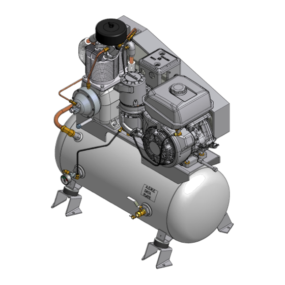
- Page 16 UNIT REPAIR PARTS ILLUSTRATION MODEL: HGR7-3K.
- Page 17 REPAIR PARTS LIST MODEL: HGR7-3K REF NO DESCRIPTION PART # R15BHU Z2409 Hex head cap screw M3460 Serrated flange hex nut M3483 Hex head cap screw M3465 Flat washer M3056 Compression fitting 86A40 Pilot valve M2853 Compression fitting, tee M2879...
- Page 18 UNIT REPAIR PARTS ILLUSTRATION MODELS: HGR5-6H, HGR5-8H, HDR5-8L, HDR5-8Y, HGR7-6K, & HGR7-8K. 305CAE800-A (Ref. Drawing)
- Page 19 REPAIR PARTS LIST MODELS: HGR5-6H, HGR5-8H, HDR5-8L, HDR5-8Y, HGR7-6K, & HGR7-8K. MODEL HGR5-6H HGR5-8H HDR5-8L HDR5-8Y HGR7-6K HGR7-8K Pump R15BHU R15BHU R15BHU R15BHU R15BHU R15BHU Pressure Gauge M519C M519C M519C M519C M519C M519C Belt Guard Z5280 Z5280 Z5280 Z5280 Z5280 Z5280 Drain Valve VP1022988...
- Page 20 UNIT REPAIR PARTS ILLUSTRATION MODELS: BGR5H, BDR5L, BDR5Y & BGR7K 306CAE800-A (Ref. Drawing) REPAIR PARTS LIST MODEL BGR-5H BDR-5L BDR-5Y BGR-7K Pump R15BHU R15BHU R15BHU R15BHU Belt Guard Z5280 Z5280 Z5280 Z5280 Base Plate P13543C CC1007176 P13543C P13543C Engine 11 HP 10 HP 10 HP 14 HP...
-
Page 21: Unit Repair Parts List
UNIT REPAIR PARTS ILLUSTRATION MODELS: HGR5-LPH, HGR7-LPK, HGR3-LPB 307CAE800-A (Ref. Drawing) REPAIR PARTS LIST MODEL HGR5-LPH HGR7-LPK HGR3-LPB Pump R15BHU R15BHU R15BHU Pressure Gauge M519C M519C M519C Belt Guard Z5280 Z5280 Z5280 Drain Valve M521 M521 M521 Tank P09502D P09502D P09502D Check Valve P05822A... - Page 22 COMPRESSOR REPAIR PARTS ILLUSTRATION Model: R10DHU & R15BHU...
- Page 23 Repair Parts List Compressor Models R10DHU & R15BHU Ref. Part Description Qty. Number Crankcase M1820 Pipe plug 64AA5 Flywheel NR7A Hex head cap screw M738 Hex nut M2955 Pipe plug 64A5 Oil level gauge RE714 Pipe nipple M492 10 Pipe cap M461 11 Governor housing gasket set (includes, items, 11A,11B,11C, &...
- Page 24 Repair Parts List Compressor Models R10DHU & R15BHU Ref. Description Part Number Qty. Piston pin R1021 Piston pin retaining ring R10102 Low pressure piston ring set Z798 High pressure piston ring set Z797 Cylinder P12237D Hex head cap screw M2345 Low pressure discharge valve assembly Z813 Valve gasket...
- Page 25 Repair Parts List Compressor Models R10DHU & R15BHU Ref. Description Part Number Qty. Gasket, Valve, HPIN, R10-30 CPQ14870A Unloader spring P01882A Guide stem P09296A Unloader finger P14119A Locking hex nut P09086A High pressure intake manifold P12304B Interstage pressure relief valve M3685 Intake filter P04999A...
-
Page 26: Compressor Repair Parts List
COMPRESSOR REPAIR PARTS ILLUSTRATION Models: R10DHU & R15BHU C462-C (Ref. Drawing) Repair Parts List Ref. No. Description Part Number Qty. Compression fitting M2879 Tube, Unloading w/Fittings ZSB250A Compression Fitting M2864 Breather Tube w/Fittings ZUB375 Compression Fitting M2864 Compression Fitting M2868 Intercooler w/Fittings Z9140 Compression Fitting... -
Page 27: Hazard Decal Listing
UNIT HAZARD DECAL LOCATIONS 308CAE800-A MODEL HGR7-3K (Ref. Drawing) UNIT HAZARD DECAL LISTING PAGE DESCRIPTION PART NO. PRODUCT LIABILITY DECAL SHEET - MASTER P10157A Unit Pressure Setting WARNING – Tank Pressure DANGER – Breathing Air DANGER – Drain Tank Daily WARNING –... -
Page 28: Unit Hazard Decals
UNIT HAZARD DECALS... -
Page 29: Pump Hazard Decals
PUMP HAZARD DECAL LISTING DESCRIPTION PART NO. PUMP DECAL SHEET – MASTER P13805A NOTICE - Lubricants NOT USED DECAL – Rotation Direction NOTICE – Read and Retain Manuals DANGER – Breathing Air DECAL – Made in the United States of America PUMP HAZARD DECALS... - Page 30 RECORD OF MAINTENANCE SERVICE RECORD OF MAINTENANCE SERVICE DAILY • CHECK OIiL LEVEL • DRAIN MOISTURE FROM TANK WEEKLY MONTHLY EVERY 3 MONTHS • • INSPECT AIR SYSTEM • CLEAN FILTER CHANGE OIL • • CLEAN COMPRESSOR INSPECT VALVE ASSEMBLIES •...
-
Page 31: Record Of Maintenance Service
RECORD OF MAINTENANCE SERVICE RECORD OF MAINTENANCE SERVICE DAILY • CHECK OIiL LEVEL • DRAIN MOISTURE FROM TANK WEEKLY MONTHLY EVERY 3 MONTHS • • INSPECT AIR SYSTEM • CLEAN FILTER CHANGE OIL • • CLEAN COMPRESSOR INSPECT VALVE ASSEMBLIES •... - Page 32 Phone (815) 875-3321 Fax (815) 872-0421 www.gardnerdenver.com Plants in Princeton, IL, and Manteca, CA Due to Gardner Denver’s continuing product development program, Copyright © 2011 Gardner Denver, Inc. specifications and materials are subject to change without notice or obligation Printed in U.S.A.
Need help?
Do you have a question about the HGR7-3K and is the answer not in the manual?
Questions and answers