Table of Contents
Advertisement
Quick Links
PK-93202-10-00-2A
WARNINGS & CAUTIONS:
• To be installed and/or used in accordance with appropriate electrical codes and regulations.
• If you are unsure about any part of these instructions, consult a qualified electrician.
• To avoid overheating and possible damage to this device and other equipment, do not install to
control a receptacle, fluorescent lighting, a motor- or a transformer-operated appliance.
• Use with incandescent or 120V halogen fixtures only.
• Total minimum wattage must exceed 40W.
Tools needed to install your Dimmer:
Slotted/Phillips Screwdriver
Electrical Tape
Pliers
Pencil
Cutters
Ruler
Installing Dimmer by itself or with other devices:
If installing Dimmer in a single device application, proceed with the
INSTALLING YOUR DIMMER section. If installing Dimmer in a multi-
device application, proceed as follows:
MULTI-DEVICE APPLICATION
NOTE: 600W devices do not have break-off side sections. Derating is
still required in multi-gang installation (see chart).
For 1000W devices: When ganging dimmers, the side sections of the
mounting strap must be removed. Use pliers to carefully bend side
sections back and forth until they break off (see Figure). The side
sections dissipate heat, so removing them requires a derating of the
dimmer's capacity (see chart).
NOTE: You only need to remove side sections if installing with other
dimmers or if it does not fit in wall box – not when installing with
mechanical switches.
Remove
all inner
side
sections
Do not
remove
outer
side
sections
Bend back and
forth to remove side
section
MAXIMUM LOAD PER DIMMER FOR MULTI-DEVICE
Cat. No.
Single
Two Devices
TGIØ6-1L
600W
500W
TGI1Ø-1L
1000W
800W
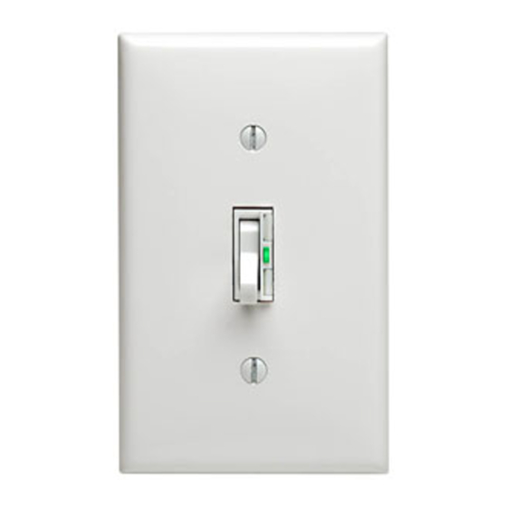
Single Pole (One location) or 3-Way (Multi-location)
Cat. No. TGIØ6-1L, 600W (Lighted)
Cat. No. TGI1Ø-1L, 1000W (Lighted)
INSTALLATION INSTRUCTIONS
INSTALLING YOUR DIMMER
NOTE: Use check boxes
WARNING:
Step 1
POWER at circuit breaker or fuse and test that power is off
before wiring!
OFF
OFF
OFF
OFF
OFF
OFF
Removing existing switch:
Step 2
wallplate and switch mounting screws. Carefully pull switch
from wall box. DO NOT remove wires attached to the switch
at this time.
Identifying your wiring application (most
Step 3
common):
NOTE: If the wiring in the wall box does not resemble any of
these configurations, consult a qualified electrician.
1
3
4
Single-Pole
1. Line (Hot)
More than
2. Neutral
2 Devices
3. Ground
400W
4. Load
700W
IMPORTANT: For 3-Way applications, note that one of the screw terminals
from the old switch being removed will usually be a different color (Black) or
labeled Common. Tag that wire with electrical tape and identify as the common
(Line or Load) in both the dimmer wall box and 3-way wall box.
Incandescent Dimmer
120VAC, 60Hz
WARNINGS & CAUTIONS:
• Use only one (1) dimmer in a 3- or 4-way circuit. The switch(es) will turn the light on at the brightness
level selected at the dimmer.
• Disconnect power at circuit breaker or fuse when servicing fixture.
• Use this device only with copper or copper clad wire. With aluminum wire use only devices marked
CO/ALR or CU/AL.
• Recommended to use with non-metallic wallplates.
√
when Steps are completed.
To avoid fire, shock, or death; TURN OFF
ON
OFF
ON
ON
OFF
ON
ON
OFF
ON
ON
OFF
ON
ON
OFF
ON
ON
OFF
ON
Remove existing
2
1
2
3
4
5
3-Way
1. Line or Load (See important
instruction below)
2. Neutral
3. Ground
4. First Traveler – note color
5. Second Traveler – note color
Preparing and connecting wires:
Step 4
• Make sure that the ends of the wires from the wall box are
straight (cut if necessary) .
• Remove 5/8" (1.6 cm) of insulation from each wire in the wall box
(shown).
• For Single-Pole Application, go to Step 5a.
• For 3-Way Application, go to Step 5b.
Cut
(if necessary)
Strip Gage
(measure bare wire here)
Single-Pole Wiring Application (600W device
Step 5a
depicted):
This wire is used in 3-way installations only.
For single pole installations, do not remove this
insulating label.
Red
Neutral
1
Black
2
Green
3
Ground
Insert wires
straight then twist
4
clockwise
Red
5/8"
(1.6 cm)
Electrical
Tape
Advertisement
Table of Contents

Related Manuals for Leviton Toggle Touch TGI06-1L


Summary of Contents for Leviton Toggle Touch TGI06-1L
- Page 1 PK-93202-10-00-2A WARNINGS & CAUTIONS: • To be installed and/or used in accordance with appropriate electrical codes and regulations. • If you are unsure about any part of these instructions, consult a qualified electrician. • To avoid overheating and possible damage to this device and other equipment, do not install to control a receptacle, fluorescent lighting, a motor- or a transformer-operated appliance.
- Page 2 Leviton is not liable for incidental, indirect, special, or consequential damages, including without...
Need help?
Do you have a question about the Toggle Touch TGI06-1L and is the answer not in the manual?
Questions and answers