Advertisement
Quick Links
DI-00X-06613-02A
WARNINGS:
• To be installed and/or used in accordance with appropriate electrical codes and regulations.
• If you are unsure about any part of these instructions, consult a qualified electrician.
• To avoid overheating and possible damage to this device and other equipment, do not install to control a
receptacle, fluorescent lighting, a motor- or a transformer-operated appliance.
• Use with magnetic low-voltage transformers, incandescent, or 120V halogen fixtures only. Use a Leviton
electronic low-voltage dimmer to control electronic (solid state) low-voltage transformers.
Tools needed to install your Dimmer:
Slotted/Philips Screwdriver
Electrical Tape
Pliers
Pencil
Cutters
Ruler
Installing Dimmer by itself or with other devices:
If installing Dimmer in a single device application, proceed with the
INSTALLING YOUR DIMMER section. If installing Dimmer in a multi-
device application, proceed as follows:
MULTI-DEVICE APPLICATION:
In multi-dimmer installations, the reduction of the dimmer's capacity is
required. Refer to the chart for maximum load per dimmer.
MAXIMUM LOAD PER DIMMER FOR MULTI-DEVICE
Cat. No.
Single
Two Devices 2 Devices
6613-PL
600VA
500VA
MAXIMUM BULB WATTAGE:
Low-voltage dimmers are rated in Volt-Amps (VA). The maximum bulb
wattage is determined by the efficiency of the transformer in the low-
voltage lighting system. Transformer efficiencies will vary from different
manufacturers; consider 75% efficient as average. Use the chart to
determine maximum bulb wattage for typical transformer efficiency
ratings.
MAXIMUM BULB WATTAGE AT 75% EFFICIENCY
Two
Rating
Single
Gang
600VA
450W
375W
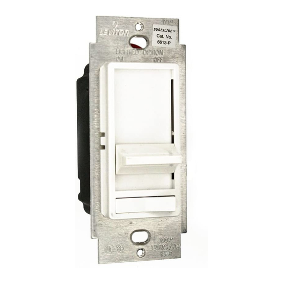
Single Pole (One location) or 3-Way (Multi-location)
Magnetic Low-Voltage Slide Dimmer
INSTALLATION INSTRUCTIONS
INSTALLING YOUR DIMMER
NOTE: Use check boxes
WARNING:
Step 1
POWER at circuit breaker or fuse and test that power is off
before wiring!
OFF
ON
OFF
ON
OFF
ON
OFF
ON
OFF
ON
OFF
ON
More than
Removing existing switch:
Step 2
400VA
and switch mounting screws. Carefully pull switch from wall
box. DO NOT remove wires attached to the switch at this
time.
Identifying your wiring application (most
Step 3
common):
NOTE: If the wiring in the wall box does not resemble any of
these configurations, consult a qualified electrician.
Single-Pole:
Look at the back of your switch.
If there are 2 wires connected to
two screw terminals (not
More than
including a green or bare copper
2 Gang
wire used for grounding), you
300W
have a Single-Pole switch.
120VAC, 60Hz
Cat. No. 6613-PL, 600VA
CAUTIONS:
• When magnetic low-voltage circuits are operated at a dim level, with all lamps inoperative, excess current may
flow through the transformer. To avoid possible transformer failure due to overcurrent, use a transformer that
incorporates thermal protection or a fuse at the primary windings.
• Use only one (1) dimmer in a 3- or 4-way circuit. The switch(es) will turn the light on at the brightness level
selected at the dimmer.
• Disconnect power at circuit breaker or fuse when servicing fixture.
• Use this device only with copper or copper clad wire. With aluminum wire use only devices marked CO/ALR or CU/AL.
√
when Steps are completed.
To avoid fire, shock, or death; TURN OFF
OFF
ON
OFF
ON
OFF
ON
OFF
ON
OFF
ON
OFF
ON
Remove existing wallplate
Tag Common
Screw Wire
3-Way:
Look at the back of your switch. If there
are 3 wires connected to three screw
terminals (not including a green or bare
copper wire used for grounding), you
have a 3-Way switch. Note that one of
the screw terminals will usually be a
different color (black) or labeled
Common. Tag that wire with electrical
tape to identify.
Disconnecting switch wires and preparing wires:
Step 4
• Disconnect wires from screw terminals or
Quickwire™ slots (shown).
• Pull off pre-cut insulation from Dimmer
leads.
• Make sure that the ends of the wires from
the wall box are straight (cut if
necessary) .
• Remove 5/8" (1.6 cm) of insulation from
each wire in the wall box (shown).
• For Single-Pole Application, go to Step
5A.
Press in slot and
• For 3-Way Application, go to Step 5B.
pull out wire
Strip 5/8"
Cut
(if necessary)
5/8"
Strip Gage
Advertisement

Subscribe to Our Youtube Channel
Related Manuals for Leviton 6613-PL


Summary of Contents for Leviton 6613-PL
- Page 1 • To avoid overheating and possible damage to this device and other equipment, do not install to control a receptacle, fluorescent lighting, a motor- or a transformer-operated appliance. • Use with magnetic low-voltage transformers, incandescent, or 120V halogen fixtures only. Use a Leviton electronic low-voltage dimmer to control electronic (solid state) low-voltage transformers.
-
Page 2: Troubleshooting
years.
Need help?
Do you have a question about the 6613-PL and is the answer not in the manual?
Questions and answers