Table of Contents
Advertisement
Quick Links
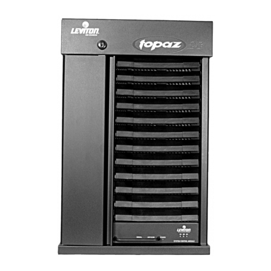
TOPAZ 24
DIMMER RACK
INSTALLATION & MAINTENANCE GUIDE
(Part # LIT-29132-1A)
Contractor: Please read these instructions before starting installation. After installation, please
forward this guide to the user for operation and maintenance instruction.
© Copyright March 2002 Leviton Manufacturing Co., Inc.
Advertisement
Table of Contents

Related Manuals for Leviton Topaz 24


Summary of Contents for Leviton Topaz 24
-
Page 1: Dimmer Rack
TOPAZ 24 DIMMER RACK INSTALLATION & MAINTENANCE GUIDE (Part # LIT-29132-1A) Contractor: Please read these instructions before starting installation. After installation, please forward this guide to the user for operation and maintenance instruction. © Copyright March 2002 Leviton Manufacturing Co., Inc. -
Page 2: Table Of Contents
Table of Contents Unpack rack(s)………………………………………………………………….. 1 Mount rack(s)…………………………………………………………………… Terminate conduits…………………………………………………………….. Convert bussing to single-phase………………………………………….…. Pull power, load and control conductors to the racks……………………… Connect power feeders………………………………………………………... 4 Label circuits……………………………………………………………………. Connect load conductors……………………………………………………… Low-voltage application notes………………………………………………… 5 Connect control conductors…………………………………………………… 6 Seal unused openings…………………………………………………………. -
Page 3: Unpack Rack(S)
Step 1 - Unpack rack(s) In each rack box you will find one TOPAZ 24 rack, two keys, one set of circuit numbers, and one installation manual (this document). Dimmer and control modules are shipped separately. Leave control module and dimmer modules in their packing and store in clean, dry place until ready to perform Step 11. - Page 4 FIGURE 1 - MOUNTING DIMENSIONS Page 2...
-
Page 5: Terminate Conduits
This is usually the left-most rack, or if provided, the auxiliary feeder rack. See Table IV, page 11 for knockout size and location. Dimmer racks can also be field punched for one 3" T.S. conduit in the top, and if provided, the auxiliary feeder rack will accept two 4"... -
Page 6: Connect Power Feeders
Step 6 - Connect power feeders • Connect the feeders at the phase, neutral and ground lugs and tighten according to Table I. See Figure 3 for lug locations. (If rack has been converted to single phase, only lugs A & C will be terminated.) Table I - Line Terminal Torque Ratings Line and Neutral Lugs (rated for copper wire only and for... -
Page 7: Connect Load Conductors
Step 8 - Connect load conductors Follow the instructions here for each dimmer type you are installing. 15/20 AMP INCANDESCENT & LOW-VOLTAGE LOADS: • Referring to Figure 4, connect the load conductor for the first (upper) dimmer to the upper load terminal, and the second load conductor to the lower load terminal. -
Page 8: Connect Control Conductors
Step 9 - Connect control conductors Follow the instructions below for the type of control you are installing. Note: All control terminals accept 24-14 AWG. (.02-2mm ) wire and are all Class 2. All cable shielding and all drain wires (wires connected to cable shielding) must be insulated. -
Page 9: Install Control Module(S)
Step 11 - Install control module(s) • Unpack the control module(s). • Set the 3 DIP switches labeled S1 on the printed circuit board (See Figure 6) as follows: SW1 – down SW2 – down SW3 – down • If the control module is a Remote type, verify that jumper JP5 is in the “REM”... -
Page 10: Set Thumbwheel Switch(Es)
Step 12 - Set thumbwheel switch(es) • Set the thumbwheel switch(es) on all TOPAZ 24 control modules according to Table III on next page. See Figure 6 (Pack 1 is usually the left-most pack). Table III - Thumbwheel Switch Settings... -
Page 11: Apply Power And Check
Step 14 - Apply power and check • Apply power to the rack. Power indicator LED should be lit on each control module. If the LED is not lit or is flashing, at least one control fuse is blown or one power leg has no voltage present. See Figure 6. CAUTION: High Voltage - all measurements with a meter and other operations within the rack must be with the rack de- energized or by a qualified electrical installer exercising extreme care. -
Page 12: Close Door
Step 18 - Close door • If desired, label circuits for easy identification later. • Close the front access door. This will aid proper cooling of the rack and restrict access to the dimmer circuit breakers. See Figure 8. ACCESS DOOR LOCK ACCESS DOOR DIMMER AND FILLER MODULES... -
Page 13: Maintenance And Specifications
Rack Enclosure: For further information on the operation of the TOPAZ 24 Rack refer to the user guides and operations manuals of the control console or architectural control stations that will be used in conjunction with this product. For additional assistance, please contact the NSI Technical Support Line, Monday through Friday, 8:00 am to 5:00 pm PST. -
Page 14: Warranty
Leviton-NSI is not liable for any incidental or consequential damages resulting from defect or failure other than repairs of the Leviton-NSI product subject to the terms of this warranty. This warranty gives you specific legal rights, and you may have other rights which vary from state to state. This warranty is expressly in lieu of all other agreements and warranties expressed or implied except as may be otherwise required by law.
Need help?
Do you have a question about the Topaz 24 and is the answer not in the manual?
Questions and answers