
Subscribe to Our Youtube Channel
Related Manuals for BRUEL & KJAER 2719


Summary of Contents for BRUEL & KJAER 2719
- Page 1 Technical Documentation Power Amplifier Type 2719 User Manual English BE 1660 – 12...
- Page 2 Power Amplifier Type 2719 User Manual May 2006 BE 1660−12...
- Page 3 Safety Considerations This apparatus has been designed and tested in accordance with IEC 61010 – 1 and EN 61010 – 1 Safety Requirements for Electrical Equipment for Measurement, Control and Laboratory Use. This manual contains information and warnings which must be fol- lowed to ensure safe operation and to retain the apparatus in safe condition.
-
Page 4: Table Of Contents
Table of Contents CHAPTER 1 Introduction......................1 CHAPTER 2 Controls....................... 3 Front Panel..........................3 Back Panel ..........................4 CHAPTER 3 Operation......................5 Preliminary ..........................5 System Checks and Connections ..................... 5 CHAPTER 4 Characteristics....................11 Signal Inputs..........................11 CHAPTER 5 Specifications .................... -
Page 6: Introduction
112 N (25 lbf) Vibration Exciter Type 4808. The RMS output-current limit is adjustable, and consequently Type 2719 can drive the 45 N (10 lbf) Vibration Exciter Type 4809 safely to full rating. The power amplifier has a usable frequency range from DC to 100 kHz. The rated AC output is 180 VA into a 0.8 Ω... - Page 7 Power Amplifier Type 2719 – User Manual...
-
Page 8: Controls
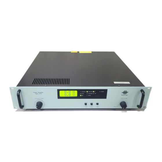
Chapter 2 Controls Front Panel Fig.2.1 Front panel of Type 2719 Current Limit A (RMS): A single-turn potentiometer for limiting RMS current output. Display: The display shows output AC current and voltage on a LCD display. • The Temperature LED indicator lights red if the Power MOS Output Transistors overheat. -
Page 9: Back Panel
Power Amplifier Type 2719 – User Manual Phase: Set the phase shift, output/input, 0 or 180 degrees. A green lit LED lamp indicates the phase shift the amplifier is set. Power: Mains On/Off button. Variable Gain (dB): Single-turn, logarithmic potentiometer for continuous adjustment of input signal level. -
Page 10: Operation
Rack Mounting Power Amplifier Type 2719 is designed to fit into 19″ standard rack system. It may be used free standing on its four rubber feet, however, when fitted in a instrumentation rack, the rubber feet must be removed. - Page 11 Mains Voltage Setting Type 2719 can be powered from a 100 V, 120 V or 230 V ±10% (50 to 60 Hz), single-phase AC mains supply. To select the correct mains voltage setting, use a small screwdriver to remove the...
- Page 12 Grounding Considerations The signal ground line of Type 2719 is permanently connected to its chassis. This is done at one point only to give the best possible immunity to mains-carried noise. Nevertheless, when using the amplifier in complex measurement setups, indiscriminate grounding of the instrument signal ground lines may introduce mains hum.
- Page 13 Power Amplifier Type 2719 – User Manual Operating Procedure After making the system checks and connections described in “System Checks and Connec- tions” on page 5, use the following procedure to commence operation: 1) Set the amplifier controls as shown below:...
- Page 14 CHAPTER 3 Operation Warning Lamps and Fault Detection If one of the red warning lamps lights, a fault has occurred in the system. Under such circum- stances, the amplifier automatically stops to protect the amplifier and vibration exciter. To help establish the cause of the shut-down, some probable faults are given in the table below.
- Page 15 Power Amplifier Type 2719 – User Manual...
-
Page 16: Characteristics
Characteristics Signal Inputs The signal inputs of Type 2719 have a minimum input impedance of 10 kΩ. The AC signal input is for connecting a vibration exciter controller or generator and is capacitive-coupled giving a –0.5 dB lower limiting frequency of approximately 15 Hz. The DC signal input is direct-coupled enabling a DC offset voltage to be applied for centring vibration exciter tables, which are statically displaced by heavy test objects. - Page 17 Power Amplifier Type 2719 – User Manual Power Output Fig.4.1 Output impedance of Type 2719 as a function of frequency and V/C Mode switch setting High Impedance Specification Limit Low Impedance Specification Limit 0.05 0.02 0.01 0.005 0.002 0.001 50k 100k...
- Page 18 CHAPTER 4 Characteristics Fig.4.2 Maximum output current rating of Type 2719 as a function of frequency Maximum Current (A) 50k 100k Frequency (Hz) 010102 As shown in Fig.4.2, the maximum output current is frequency-dependent. The maximum power output is 180 VA, which is obtained using exciters with a nominal load impedance of 0.8 Ω.
- Page 19 Power Amplifier Type 2719 – User Manual Fig.4.3 Maximum output voltage, current and power output ratings of Type 2719 as a function of exciter load impedance, valid at frequencies from 40 Hz to 10 kHz Vibration Exciter Type 4808 Vibration Exciter...
- Page 20 V/C Mode switch, as shown by the response curves for small signals given in Fig.4.4. Fig.4.4 Frequency response in Voltage Mode of Type 2719 for power output levels up to 20 VA DC Input Low Impedance DC Input Specification Limit...
- Page 21 Power Amplifier Type 2719 – User Manual Distortion The percentage of harmonic distortion produced by Type 2719 is shown in Fig.4.5. Considering the 180 VA power output rating of the amplifier, the amount of distortion is very low. This can be attributed to the generous amount of feedback applied and the use of a direct-coupled input.
-
Page 22: Specifications
Chapter 5 Specifications COMPLIANCE WITH STANDARDS FREQUENCY RANGE compliance with EMC Directive Full Capacity: 40 Hz to10 kHz Reduced Capacity: DC to 100 kHz compliance with EMC Requirements of Australia and New Zealand FREQUENCY RESPONSE Typical small signal response in low impedance mode: DC Input: DC to 15 kHz ±0.5 dB;... - Page 23 Power Amplifier Type 2719 – User Manual RMS Current Monitor for approximate indication POWER REQUIREMENTS – (also available from BNC connector at back panel with Single phase 100, 120, 230 V RMS, ±10%. Approx. read-out accuracy ±2%) 400 VA at full load...
-
Page 24: Service And Repair
Chapter 6 Service and Repair Type 2719 is designed and constructed to provide many years of safe, reliable operation. How- ever, if the correct function or operating safety of the instrument is impaired, immediately disconnect it from the mains source and secure it against unintended operation. For repair contact your local Brüel &... - Page 25 Power Amplifier Type 2719 – User Manual...
- Page 26 HEADQUARTERS: DK-2850 Nærum · Denmark · Telephone: +45 4580 0500 · Fax: +45 4580 1405 · www.bksv.com · info@bksv.com Australia (+61) 2 9889-8888 · Austria (+43) 1 865 74 00 · Brazil (+55)11 5188-8161 · Canada (+1) 514 695-8225 China (+86) 10 680 29906 · Czech Republic (+420) 2 6702 1100 · Finland (+358) 9-521 300 · France (+33) 1 69 90 71 00 Germany (+49) 421 17 87 0 ·...
Need help?
Do you have a question about the 2719 and is the answer not in the manual?
Questions and answers