Table of Contents
Advertisement
Quick Links
Advertisement
Table of Contents

Subscribe to Our Youtube Channel
Related Manuals for BRUEL & KJAER 2734


Summary of Contents for BRUEL & KJAER 2734
- Page 1 USER MANUAL Power Amplifier Type 2734 BE 1837 – 12 English ...
- Page 3 Power Amplifier Type 2734 User Manual BE 183712 December 2015 www.bksv.com...
- Page 4 Health and Safety Considerations Electrical Hazards This apparatus has been designed and tested in accordance Warning: Any adjustment, maintenance and Safety with IEC/EN 61010 – 1 ANSI/UL 61010 – 1 repair of the open apparatus under voltage must Requirements for Electrical Equipment for Measurement, be avoided as far as possible and, if unavoidable, Control and Laboratory Use .
- Page 6 Brüel & Kjær has made every effort to ensure the accuracy of Brüel & Kjær and all other trademarks, service marks, trade the information contained in this document. No responsibility names, logos and product names are the property of is accepted for any errors or omissions herein. It is the Brüel &...
-
Page 7: Table Of Contents
Contents CHAPTER 1 Introduction, Safety Instructions and User Responsibility ........................ 1 Welcome........................... 1 Important Safety Instructions.................... 1 User Responsibility ........................ 2 Unpacking .......................... 3 CHAPTER 2 Overview .......................... 5 Front Panel.......................... 5 Wireless Audio Transmitter (Type 2734‐B only) ............... 7 Rear Panel.......................... 9 Side Panel .......................... 9 CHAPTER 3 Installation .......................... 11 Setting Up the Amplifier ...................... 11 Operating Voltage........................ 11 Grounding .......................... 12 Installing the Wireless Audio Receiver ................... 12 Installing the Wireless Audio Transmitter ................ 14 CHAPTER 4 Operation .......................... 17 Functional Diagram......................... 17... - Page 8 CHAPTER 5 Protection Features ....................... 25 CHAPTER 6 Maintenance, Service and Repair................... 27 Air Filter .......................... 27 Fuse ............................ 27 Troubleshooting ........................ 28 CHAPTER 7 Specifications ........................ 29...
-
Page 9: Introduction, Safety Instructions And User Responsibility
1.1.1 Conventions “Amplifier” refers to Type 2734-A or Type 2734-B if the description is valid for both. “Analyzer” refers to Type 2250 or Type 2270 if the description is valid for both. Important Safety Instructions Before using your amplifier, carefully read the operating and safety instructions applicable to you. -
Page 10: User Responsibility
Power Amplifier Type 2734 – User Manual 9) Connect only to AC power outlets rated 200 – 240 V or 100 – 130 V, 50 – 60 Hz. 10) Do not use this amplifier if the power cord is broken or frayed. Protect the power cord don’t stand on it or pinch it, particularly at the plug and the point where it meets the apparatus. -
Page 11: Unpacking
CHAPTER 1 Introduction, Safety Instructions and User Responsibility 1.3.3 Wireless Audio System When using the wireless audio system (included in Type 2734-B), ensure that no Notice: RF disturbance will be caused in the environment and that any required permission or license has been obtained. Unpacking Carefully open the shipping carton and check for any noticeable damage. Every Brüel & Kjær amplifier is tested and inspected before leaving the factory and should arrive in perfect condition. - Page 12 Power Amplifier Type 2734 – User Manual...
-
Page 13: Overview
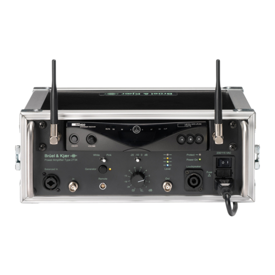
The calibrated dials and indicators allow setups to be easily reproduced in future tests. The amplifier comes in two versions, Types 2734-A and 2734-B. Type 2734-B includes the Wireless Audio System UL-0256, currently using the AKG WMS 470, allowing you to transmit a generator signal from an analyzer to the amplifier through partitions in a building. - Page 14 16) Mains power switch – Switches power to the unit on and off. Type 2734-B is also equipped with Wireless Audio System UL-0256. The numbers preceded by B in figure 2.1 also refer to the numbers in figures 1 and 2 on page ii in the AKG manual for this receiver, AKG SR 470.
-
Page 15: Wireless Audio Transmitter (Type 2734-B Only)
8) Antenna A/B – BNC sockets for connecting the two supplied UHF whip antennas. Wireless Audio Transmitter (Type 2734‐B only) Type 2734-B includes Wireless Audio System UL-0256 (AKG PT 470). The numbers in Fig. 2.2 also refer to the numbers in figure 4 on page iii in the AKG manual of this transmitter. - Page 16 Power Amplifier Type 2734 – User Manual 10) State Switch – this slide switch provides three positions: – ON: The microphone output signal is fed to the transmitter for transmission to the receiver (normal mode). The status LED (B-20) is illuminated green. –...
-
Page 17: Rear Panel
Fig. 2.3 Rear panel Brüel & Kjær 115 V AC / 60 Hz Type 2734 Serial No. 230 V AC / 50 Hz Made in he Netherlands 090103/1 The voltage selector (Fig. 2.3, circled) toggles between nominal 230 V and 115 V mains voltage. - Page 18 Power Amplifier Type 2734 – User Manual...
-
Page 19: Installation
3) Take out the mains cord from the separate cardboard box. The mains cord can be stored in the front panel cover. 4) To use the wireless audio receiver (Type 2734-B only), affix the whip antennas to the corresponding BNC sockets (B-11). To use the antennas with Type 2734-B placed vertically, you can use right-angle BNC adapters. -
Page 20: Grounding
Power Amplifier Type 2734 – User Manual Grounding ⚠ For safe operation, ensure that the mains outlet is equipped with an earth Warning: connection and that the protective earth conductor is not interrupted in any way. Do not use extension cables without protective earth conductors. - Page 21 4) Insert the receiver into the amplifier and mount the screws and spring washers to the front cover plate. Fig. 3.3 Mounting the wireless audio receiver (shown without antennas) 230/115 V AC / 650 W Brüel & Kjær White Pink -20 -10 0 dB Protect Power Amplifier Type 2734 Power On Loudspeaker Balanced In Generator Level Fuse Fuse Remote 090095/1...
-
Page 22: Installing The Wireless Audio Transmitter
Power Amplifier Type 2734 – User Manual 5) Turn the receiver on by pressing the power button (Fig. 2.1, B-1). 6) Set the output level control (Fig. 2.1, B-9) to its maximum position. 7) Insert both antennas, pointing them upwards. They can be redirected to optimise reception based on local conditions. - Page 23 CHAPTER 3 Installation 3) Connect the analyzer’s output to the amplifier’s input (Fig. 2.1, 2) or balanced input (Fig. 2.1, 1) socket. 4) Set amplifier’s sensitivity (Fig. 2.1, 7) to –10 dB and adjust the attenuator (Fig. 2.1, 8) to make the red level indicator (Fig.
- Page 24 Power Amplifier Type 2734 – User Manual...
-
Page 25: Operation
Chapter 4 Operation Functional Diagram Fig. 4.1 Functional diagram of the amplifier Wireless Audio Receiver Sensitivity Attenuation –20...0 dB –30...0 dB XLR (internal) Protect indicator (red) 27 dB Power Stage Level Indicator re output +7 dB clip level yellow 0 dB S+A+16 dB green –6 dB blue –30 dB Gain... -
Page 26: Powering Up
Power Amplifier Type 2734 – User Manual The Protect indicator illuminates if protection circuits are activated to prevent the power stage from being damaged due to an overload or overheat condition. Powering Up It is recommended to always turn down the attenuator control knob before turning on the amplifier, in order to prevent sudden noise or speaker damage in case a high signal is present at an input. -
Page 27: Inputs
CHAPTER 4 Operation Table 4.1 Available sensitivity settings, nominal input voltages and headroom Headroom [dB] Headroom [dB] Nominal input voltage [V Sensitivity [dB] Balanced Unbalanced –10 –20 Table 4.2 Available attenuation settings Attenuation [dB] –30, –24, –18, –12, –9, –6, –5, –4, –3, –2, –1, 0 Inputs 4.5.1 Connection Types The amplifier is equipped with balanced and unbalanced inputs. Balanced signals are less sensitive to AC hum and radio interference, that is particularly relevant if low level signals have to be transferred over a long distance. -
Page 28: Outputs
Power Amplifier Type 2734 – User Manual Fig. 4.2 Connecting a source (left end of cable) to an amplifier input (right end of cable). Balanced source via balanced cable to XLR input Balanced source via balanced cable to phone jack input Unbalanced source via balanced cable to XLR input Unbalanced source via balanced cable to phone jack input... -
Page 29: Level Indicator
CHAPTER 4 Operation Level Indicator The level indicator consists of four LEDs, each of which is provided with a (fast on/delayed off) function and illuminates above a certain peak signal level relative to the level at which the speaker output clips, as shown in Table 4.3. The blue LED indicates whether any significant signal is present at one of the inputs. -
Page 30: Internal Noise Generator
Power Amplifier Type 2734 – User Manual �� The following step can be carried out with the loudspeaker cable disconnected. Hint: 7) When using a source with unknown output voltage, turn the source on and then select the maximum sensitivity at which the red level indicator does not illuminate. If this indicator illuminates even at a sensitivity of –20 dB, reduce the source output level. - Page 31 CHAPTER 4 Operation Fig. 4.3 Frequency band noise spectra of the amplifier. Left: white noise spectrum, tilted by –1 dB per third octave; Right: pink noise spectrum; Bottom: equalized noise spectrum. −5 −5 −10 −10 −15 −15 −20 −20 31.5 63 125 250 500 31.5 63 125 250 500 [Hz] [Hz] −5 −10 −15 −20 31.5 63 125 250 500 [Hz] 090105/1 The noise generator can also be switched on and off by the optional UA-1476 wireless remote control, depicted in Fig.
-
Page 32: Fan
Power Amplifier Type 2734 – User Manual Fig. 4.4 Socket for connection UA 1476 wireless to sound level meter remote control receiver On/Off and transmitter. Receiver Transmitter 090096 The generator can also be switched on and off by connecting pin 4 of the remote control socket to ground (pin 1), or by connecting pin 3 to any voltage between 3 and 12 V with reference to ground, for example, pin 2 (+12 V). -
Page 33: Protection Features
Chapter 5 Protection Features The amplifier is equipped with several protection features. Should a fault condition arise, one of the protection circuits will activate. It may shut down the amplifier and illuminate the Protect LED (Fig. 2.1, 11) on the front panel. A protection circuit activates under one of the following conditions. - Page 34 Power Amplifier Type 2734 – User Manual...
-
Page 35: Maintenance, Service And Repair
Chapter 6 Maintenance, Service and Repair Under normal use, the amplifier should provide years of trouble-free service. In some extreme cases, however, it may be necessary for authorised service personnel to clean the inside of the amplifier. These conditions usually occur after prolonged use in dusty environments. Air Filter If the amplifier is used in dusty environments, the air filter will have to be cleaned from time to time. -
Page 36: Troubleshooting
Power Amplifier Type 2734 – User Manual In all other cases, (fuse blows again, amplifier is still not responding, etc.) the fault is more serious. In that case return the amplifier to your supplier or an approved service centre. After replacing the operational fuse, do not forget to replace the spare fuse too. Littlefuse T 5 AH 250V 215 series fuses (part number 215005.MXP) are recommended. -
Page 37: Chapter 7 Specifications
Chapter 7 Specifications MAXIMUM OUTPUT POWER FREQUENCY RESPONSE (20 HZ – 20 KHZ) (TA = 25 °C, 230 V AC/50 Hz, 1 kHz, THD < 10% ) Line output: –1 dB 4 : 500 W Power output: –1 dB 6 : 330 W See also Fig.7.1 8 : 250 W SNR (MAX POWER 1 KHZ)/(SILENCE 0…20 KHZ) CONTINUOUS OUTPUT POWER (1 KHZ, 6 Line output: 105 dB With air filter, TA = 25 °C: 250 W Power output: 100 dB Without air filter,TA = 25 °C: 330 W THD+N (20 HZ –... - Page 38 Fuse: Littelfuse T 5 AH 250V 215 series, 215005.MXP balanced level switchable to ‐30 or 0 dBm Maximum power consumption: 650 W MECHANICAL(RECEIVER) MECHANICAL Dimensions: 200 x 44 x 190 mm Dimensions W x H x D: 330 x 130 x 310 mm (13 x 5.1 x 12 “) (7.8 x 1.7 x 7.4 “) Weight including mains cord in lid Weight: 972 g (2.2 lbs.) Type 2734‐A: 5.0 kg (11 lbs.) Type 2734‐B: 6.0 kg (13 lbs.) Part of the UL-0256 Wireless Audio System, included in Type 2734-B...
- Page 39 Fig.7.1 Frequency Responses measured at a 0 dB output power of 300 W into 6 up to 20 kHz and of 20 W up from 20 kHz Power Out into 6 Ohms [dB] Line Out [dB] -1 -12 100k 090106/1 Ordering Information Type 2734‐A Power Amplifier OPTIONAL ACCESSORIES Type 2734‐B Power Amplifier with Wireless Audio ZE‐0948 USB Audio Interface System UL‐0256 Upgrade Kit from Type 2734‐A to 2734‐B, includes Wireless Audio System and COMPONENTS INCLUDED WITH THE AMPLIFIER AO‐1456 cable for transmitter...
- Page 40 Power Amplifier Type 2734 – User Manual Compliance with Standards The CE marking is the manufacturer's declaration that the product meets the requirements of the applicable EU directives RCM mark indicates compliance with applicable ACMA technical standards – that is, for telecommunications, radio communications, EMC and EME China RoHS mark indicates compliance with administrative measures on the control of pollution caused by electronic information products according to the Ministry of Information Industries of the People’s Republic of China WEEE mark indicates compliance with the EU WEEE Directive Safety EN/IEC 61010–1 and ANSI/UL 61010–1: Safety requirements for electrical equipment for measurement, control and laboratory use. EMC Emission EN/IEC 61000–6–4: Generic emission standard for industrial environments. CISPR 22: Radio disturbance characteristics of information technology equipment. Class A Limits. FCC Rules, Part 15: Complies with the limits for a Class A digital device EMC Immunity EN/IEC 61000–6–1: Generic standards – Immunity for residential, commercial and light‐industrial environments. EN/IEC 61000–6–2: Generic standards ‐ Immunity for industrial environments. EN/IEC 61326–1: Electrical equipment for measurement, control and laboratory use – EMC requirements Note: The above is only guaranteed using accessories included in this document. Temperature IEC 60068–2–1 & IEC 60068–2–2: Environmental Testing. Cold and Dry Heat. Operating Temperature: 0 to +50°C (32 to 122°F) Storage Temperature: 0 to +70°C (32 to 158°F) Humidity IEC 60068–2–78: Damp Heat: 90% RH (non‐condensing at 40 °C (104 °F))
- Page 44 © Brüel & Kjær. All rights reserved. www.bksv.com...
Need help?
Do you have a question about the 2734 and is the answer not in the manual?
Questions and answers
Eu gostaria de ter uma ideia do valor do 2734 A e B