Table of Contents
Advertisement
Quick Links
Advertisement
Table of Contents

Related Manuals for BRUEL & KJAER 2525


Summary of Contents for BRUEL & KJAER 2525
- Page 1 Measuring Amplifier Type 2525 Volume 1: Operation English BE 1406 – 12...
- Page 3 Measuring Amplifier Type 2525 From Serial number: 1899378 Revision March 1998 Brüel & Kjær BE 1406 – 12...
- Page 4 All rights reserved. No part of this publication may be reproduced or distributed in any form, or by any means, without prior consent in writing from Brüel & Kjær Sound & Vibration Measurement A/S, Nærum, Denmark. 0 – 2 Measuring Ampifier Type 2525 Brüel & Kjær User Manual Vol.1...
-
Page 5: Table Of Contents
Contents Introduction and Specifications ............... 1–1 Introduction ......................... 1–2 Specifications 2525 ...................... 1– 4 How to Use this Manual ..................... 1–6 Controls and Connections ..................2 – 1 Front Panel ........................2 – 2 Rear Panel ........................ 2 – 3 Operation Overview .................... - Page 6 Instructions for Measurement..................6 – 3 Conclusion ........................6 – 8 Service and Repair ...................... 7 – 1 Introduction ......................... 7–2 Determining the Software Version Number.............. 7–2 Index ............................8 – 1 0 – 4 Measuring Ampifier Type 2525 Brüel & Kjær User Manual Vol.1...
-
Page 7: Introduction And Specifications
Chapter 1 Introduction and Specifications Introduction ..........................1 – 2 Specifications 2525 ......................1 – 4 How to Use this Manual ....................1 – 6 BE 1406 – 12 Measuring Ampifier Type 2525 1 – 1 User Manual Vol.1... -
Page 8: Introduction
Chapter 1 – Introduction and Specifications Introduction Introduction The Measuring Amplifier Type 2525 is a low-noise amplifier featuring both Charge ® and DeltaTron inputs, an extended, menu-based, manual user-interface and the option of remote, automated control from one of its two interfaces. - Page 9 The commands and use of the interface are fully treated in Volume 2 of this manual. BE 1406 – 12 Measuring Ampifier Type 2525 1 – 3 User Manual Vol.1...
-
Page 10: Specifications 2525
(<3 V or >21 V) accuracy value (e.g. +5%, −15%, etc.) Alarm Output: PREAMP OUTPUT: In the 15-pole D-Sub socket on rear of amplifier BNC socket on rear 1 – 4 Measuring Ampifier Type 2525 Brüel & Kjær User Manual Vol.1... - Page 11 Mains: 90 V–127 V or 200 V–240 V; 24 VA Measured with max. gain and 50 Ω AC termination Measured with max. gain and 1 nF termination BE 1406 – 12 Measuring Ampifier Type 2525 1 – 5 User Manual Vol.1...
-
Page 12: How To Use This Manual
Chapter 7 includes a word about service and repair of the amplifier. Chapter 8 contains the Index. 1 – 6 Measuring Ampifier Type 2525 Brüel & Kjær User Manual Vol.1... -
Page 13: Controls And Connections
Chapter 2 Controls and Connections Front Panel ..........................2 – 2 Rear Panel ......................... 2 – 3 BE 1406 – 12 Measuring Ampifier Type 2525 2 – 1 User Manual Vol.1... -
Page 14: Front Panel
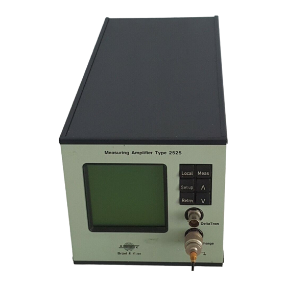
Chapter 2 – Controls and Connections Front Panel Front Panel Fig.2.1 Front panel of Measuring Amplifier Type 2525 The amplifier pushkeys control measurement, allowing you to Local Meas move between menus and select options, specify parameter val- ues, and shift between remote and local mode. See Chapter 3 for ∧... -
Page 15: Rear Panel
Chapter 2 – Controls and Connections Rear Panel Rear Panel Fig.2.2 Rear panel of Measuring Amplifier Type 2525 AC Output For connection of the processed signal to analyzers, recorders and other measurement devices in the measurement chain after the amplifier. See section 1.2 for full specification. - Page 16 Input Additional Filter Select Output Gain RMS Detector Peak Detector Output Amplifier Acc/Vel Integrators 941571e Fig.2.3 Location of Preamp output in 2525 design Ground Ground Input to external filter, signal Input to external filter, ground, n.c. Output from external filter,...
-
Page 17: Operation Overview
Chapter 3 Operation Overview Preliminary ..........................3 – 2 Set-up and Measurement ....................3 – 4 BE 1406 – 12 Measuring Ampifier Type 2525 3 – 1 User Manual Vol.1... -
Page 18: Preliminary
3.1.3 Installing and Removing Fuses The fuses for the 2525 are contained in the fuse cartridge on the rear panel of the amplifier just above the Power On/Off switch. If you need to replace a damaged fuse, or if you need to change the mains voltage, you must remove the cartridge and replace the fuse(s) as follows: 1. - Page 19 5. Re-insert the cartridge into the amplifier. 3.1.4 Rack Mounting The 2525 is normally used free-standing on its four rubber feet. However, on cus- tomer request, a special panel is available to allow the amplifier can be mounted on 19 inch instrumentation rack.
-
Page 20: Set-Up And Measurement
(called pushkeys) on the front panel, or via one of the interfaces (IEEE– 488 or serial). Using the 2525 via interface commands is the subject of Volume 2 of this manual and will not be discussed further here. - Page 21 “speeder”, allowing you to scroll through values very quickly. Every screen on the amplifier indicates which choices are available for selection or specification of a set-up or measurement option/parameter. If an option/parameter BE 1406 – 12 Measuring Ampifier Type 2525 3 – 5 User Manual Vol.1...
- Page 22 This set of menus contains all the parameter selections available for setting the amplifier for making a measurement. These menus are discussed in detail in Chapter 5. 3 – 6 Measuring Ampifier Type 2525 Brüel & Kjær User Manual Vol.1...
-
Page 23: The Menus
Chapter 4 The Menus Introduction ............................4 – 2 Main Set-up ............................4 – 2 BE 1406 – 12 Measuring Ampifier Type 2525 4 – 1 User Manual Vol.1... -
Page 24: Introduction
Introduction Introduction The menu system of the 2525 amplifier can best be seen by using Fig.4.4 as a reference (this is the overview diagram which lies at the back of this chapter and can be folded out to show all the amplifier menu options). - Page 25 4.2.3). The sine reference is applied to the input stage of the amplifier when ON is selected, and is factory- BE 1406 – 12 Measuring Ampifier Type 2525 4 – 3 User Manual Vol.1...
- Page 26 100 and 1.0 mV respectively, due to attenuation by the integration stages of the amplifier. To check the correct function of the 2525, a voltmeter or other indicating instru- ment may be used to measure the test voltage. With the amplifier control settings prescribed in Table 4.1, the test voltage output levels should be within ±...
- Page 27 DTR line is set On. When the external device sets the DSR control line (pin 6) off, the amplifier stops transmitting until the DSR goes back on. BE 1406 – 12 Measuring Ampifier Type 2525 4 – 5 User Manual Vol.1...
- Page 28 Systeme Internationale (metric), according to ISO1000 in metres, and Newtons Inches, lbf, g’s IMPERIAL 4.2.8 Decimal Point This menu allows you to specify the format measurement values will appear in on the amplifier screen: 4 – 6 Measuring Ampifier Type 2525 Brüel & Kjær User Manual Vol.1...
- Page 29 The Digits + Bargraph option allows you to view the measurement as it takes place in terms of a bar graph as well as showing each current level. The display appears as shown in Fig.4.2. LARGE DIGITS *Patent pending BE 1406 – 12 Measuring Ampifier Type 2525 4 – 7 User Manual Vol.1...
- Page 30 To Main set-up –1 AC out:100 mV/ms Unsettled –1 Ch. 1 mm/s – – – – REF GEN Remote Addressed 941414e Fig.4.3 The Display Mode Digits + Select selected 4 – 8 Measuring Ampifier Type 2525 Brüel & Kjær User Manual Vol.1...
- Page 31 Off after 5 min. Off after 10 min. Note: Each time a pushkey is activated the display back light will go on for the duration specified. BE 1406 – 12 Measuring Ampifier Type 2525 4 – 9 User Manual Vol.1...
- Page 32 Chapter 4 – The Menus Main Set-up 4 – 10 Measuring Ampifier Type 2525 Brüel & Kjær User Manual Vol.1...
- Page 33 Level Exceed Time Level Exceed Time xx s Detector DC Output Detector DC Output + Peak - Peak Peak-to-Peak 941345e Fig.4.4 2525 menu overview NOTE: FOLD-OUT!!! BE 1406 – 12 Measuring Ampifier Type 2525 4 – 11 User Manual Vol.1...
- Page 34 Chapter 4 – The Menus Main Set-up 4 – 12 Measuring Ampifier Type 2525 Brüel & Kjær User Manual Vol.1...
-
Page 35: The Measurement Set-Up Menu
Peak Hold Time ..........................5 – 7 5.10 Autorange .............................. 5 – 7 5.11 Alarm Function ..........................5 – 8 5.12 Detector DC Output ........................5 – 10 BE 1406 – 12 Measuring Ampifier Type 2525 5 – 1 User Manual Vol.1... -
Page 36: Introduction
This menu is for selecting the calculations required for the measurement based on the transducer type used for the measurement. If you are using an accelerometer you must choose the units for the calculation. 5 – 2 Measuring Ampifier Type 2525 Brüel & Kjær User Manual Vol.1... -
Page 37: Transducer Sensitivity
This menu allows you to select the type of input you will be using on the amplifier. The options are: ® This input is designed for the DeltaTron family of DELTATRON transducers. These are transducers with built-in preamplifiers. BE 1406 – 12 Measuring Ampifier Type 2525 5 – 3 User Manual Vol.1... -
Page 38: Gain
1.7 pC/ms can be normalized to a convenient output sensitivi- –2 ty (for example 1 mV/ms ). This greatly simplifies setting up, calibrating and reading the measuring system. 5 – 4 Measuring Ampifier Type 2525 Brüel & Kjær User Manual Vol.1... -
Page 39: Frequency Range
A low frequency capability is necessary for measurements of long duration impulses and quasi-static vibrations. In general very low frequencies produce environmental- ly induced low frequency noise which will mask the vibration output. BE 1406 – 12 Measuring Ampifier Type 2525 5 – 5 User Manual Vol.1... -
Page 40: Additional Filter
An internal filter is applied. This is an optional feature INTERNAL allowing you to add your own filter card to the 2525 which is then coupled into the signal path. This option is available on special request. Customer filters are identified on the screen in accordance with customer wishes. -
Page 41: Peak Hold Time
Input and Output Gains cannot be changed. During the range shift of the autorange the alarm function is not active. BE 1406 – 12 Measuring Ampifier Type 2525 5 – 7 User Manual Vol.1... -
Page 42: Alarm Function
5.11.1 Alarm On/Off Select to set an alarm, select if you do not want an alarm. The default is 5 – 8 Measuring Ampifier Type 2525 Brüel & Kjær User Manual Vol.1... - Page 43 5.11.5 Alarm Hold Time Once the alarm is activated the alarm will remain activated for the specified hold time. Range: From 1 to 60 s Resolution: Default: BE 1406 – 12 Measuring Ampifier Type 2525 5 – 9 User Manual Vol.1...
-
Page 44: Detector Dc Output
The 0 and 1 V options are used for calibration of output to the DC recorder. Output is digitally generated and updated at 125 ms intervals (the same interval as the LCD meter is updated). 5 – 10 Measuring Ampifier Type 2525 Brüel & Kjær User Manual Vol.1... -
Page 45: Making A Measurement
..........................6 – 2 Principle ........................... 6 – 2 Mounting the Accelerometer ..................6 – 2 Instructions for Measurement ..................6 – 3 Conclusion ..........................6 – 8 BE 1406 – 12 Measuring Ampifier Type 2525 6 – 1 User Manual Vol.1... -
Page 46: Introduction
1. Make sure that the surface of the test piece is as clean and smooth as is practi- cally possible. This will ensure the highest possible resonance frequency. 6 – 2 Measuring Ampifier Type 2525 Brüel & Kjær User Manual Vol.1... -
Page 47: Instructions For Measurement
2. Connect the three-prong mains cable to the contact on the back panel of the amplifier, and plug into a grounded socket. BE 1406 – 12 Measuring Ampifier Type 2525 6 – 3 User Manual Vol.1... - Page 48 Input Type: Floating or grounded according to the measurement set-up as specified in section 3.1.5 Upper Frequency Limit: 30 kHz Lower Frequency Limit: 10 Hz 6 – 4 Measuring Ampifier Type 2525 Brüel & Kjær User Manual Vol.1...
- Page 49 Digits + Select mode menu, and move the cursor to Output Gain. Press Setup and use to increase the output gain until “SIG OVL” appears on the screen. BE 1406 – 12 Measuring Ampifier Type 2525 6 – 5 User Manual Vol.1...
- Page 50 Alarm Level = Select a value which comes very close to the measured RMS value you noted in (4), but is just a little higher Alarm (Level) Hold Time = 1 s 6 – 6 Measuring Ampifier Type 2525 Brüel & Kjær User Manual Vol.1...
- Page 51 3. Go into Lin./dB Units and select dB. 4. In the Measurement Set-up menu, select Peak Hold Time, and specify about 20 seconds. 5. Press Meas BE 1406 – 12 Measuring Ampifier Type 2525 6 – 7 User Manual Vol.1...
-
Page 52: Conclusion
Application Notes. The remaining functions should, after this brief introduction, be easy to use and self-explanatory, if you have read the rest of this manual. 6 – 8 Measuring Ampifier Type 2525 Brüel & Kjær User Manual Vol.1... -
Page 53: Service And Repair
Chapter 7 Service and Repair Introduction ............................7 – 2 Determining the Software Version Number ..............7 – 2 BE 1406 – 12 Measuring Ampifier Type 2525 7 – 1 User Manual Vol.1... -
Page 54: Introduction
Introduction Introduction The 2525 is designed to provide many years of trouble free operation. However, if a fault occurs, disconnect all power to prevent further damage. For repair, consult your local Brüel & Kjær service representative. Repair should never be attempted by persons not qualified in the service of electronic instrumentation. -
Page 55: Index
Lin./dB Read-out ............4 – 3 Detector DC output ............5 – 10 Displacement ..............5 – 3 Linear averaging ............5 – 7 Display Mode ..............4 – 7 Logarithmic averaging ..........5 – 6 BE 1406 – 12 Measuring Ampifier Type 2525 8 – 1 User Manual Vol.1... - Page 56 Lin ................4 – 3 Using .................3 – 5 Upper frequency limit ..........5 – 5 Rack mounting ..............3 – 3 Read-out .................4 – 3 Velocity ................5 – 3 8 – 2 Measuring Ampifier Type 2525 Brüel & Kjær User Manual Vol.1...
Need help?
Do you have a question about the 2525 and is the answer not in the manual?
Questions and answers