
Subscribe to Our Youtube Channel
Related Manuals for BRUEL & KJAER 2732


Summary of Contents for BRUEL & KJAER 2732
- Page 1 Technical Documentation Power Amplifier Type 2732 User Manual English BE 1662 – 12...
- Page 2 Power Amplifier Type 2732 User Manual October 2005 BE 1662−12...
- Page 3 Safety Considerations This apparatus has been designed and tested in accordance with IEC 61010 – 1 and EN 61010 – 1 Safety Requirements for Electrical Equipment for Measurement, Control and Laboratory Use. This manual contains information and warnings which must be fol- lowed to ensure safe operation and to retain the apparatus in safe condition.
-
Page 4: Table Of Contents
Contents CHAPTER 1 Introduction......................1 CHAPTER 2 Controls....................... 3 Front Panel..........................3 Back Panel ..........................4 CHAPTER 3 Operation......................7 Preliminary ..........................7 Environment......................... 7 Rack Mounting ........................7 System Checks and Connections ..................... 7 Exciter Connections ......................7 Mains Supply Connections ....................8 Fuse Check and Replacement..................... -
Page 6: Introduction
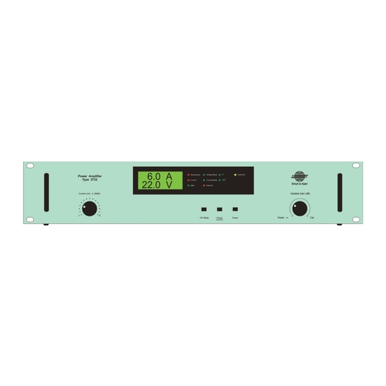
Chapter 1 Introduction Power Amplifier Type 2732 has been especially designed to drive Modal Exciter Type 4824 but can be used with any vibration or modal exciter requiring a 120 VA power amplifier. The rated AC output is 120 VA into a 4 Ω exciter or resistive load. The power amplifier has a usable frequency range from 40 Hz to 15 kHz (full capacity) or DC to 150 kHz (reduced capacity). - Page 7 Power Amplifier Type 2732 – User Manual...
-
Page 8: Controls
The LED Indicator for Current lights red when output current to the load exceeds the current – Limit value set. Power Amplifier Type 2732 is then put in the Reset State – The LED Indicator for Output V/C Mode lights green showing the Output Mode, Current Mode or Voltage Mode –... -
Page 9: Back Panel
>10 k Ω. If DC Static Centering Unit Type 1056 (optional) is used, the output from Type 1056 – using a BNC to BNC cable – must be connected to the Signal Input DC socket of Type 2732. Signal Input AC: BNC socket providing a capacitive-coupled input to the amplifier. - Page 10 CHAPTER 2 Controls Current Monitor: BNC socket providing output of the amplifier output waveform (including DC component) for display on an oscilloscope. The monitor signal is the amplifier output current as 0.1 V/A.
- Page 11 Power Amplifier Type 2732 – User Manual...
-
Page 12: Operation
Type 2732 will be put in Reset State to prevent overheating of the transistors. -
Page 13: Mains Supply Connections
Mains Voltage Setting Type 2732 can be powered from a 100 V, 120 V or 230 V ± 10% (50 – 60 Hz), single-phase AC mains supply. To select the correct mains voltage setting, use a small screwdriver to remove the... -
Page 14: Operating Procedure
CHAPTER 3 Operation Mains Socket Connection Once the mains voltage setting and fuse are correct, use the power cable provided to connect the mains to the mains input socket of the amplifier. Note that for maximum operating safety, the protective (green/yellow) conductor of the cable should be connected to a suitable earth, such as the earth contact of a mains outlet socket. -
Page 15: Warning Lamps And Fault Detection
Power Amplifier Type 2732 – User Manual Warning Lamps and Fault Detection If one of the red warning lamps lights, a fault has occurred in the system. Under such circum- stances, the test is automatically stopped to protect the amplifier and exciter. To help establish the cause of the shut-down, some probable faults are given in Table 3.1. -
Page 16: Characteristics
Characteristics Signal Inputs The signal inputs of Type 2732 have a minimum input impedance of 10 kΩ. The AC signal input is for connecting an exciter controller or generator and is capacitive coupled giving a ±0.5 dB lower limiting frequency of approximately 15 Hz. The DC signal input is direct coupled enabling a DC offset voltage to be applied for centering the exciter armature. - Page 17 100k Frequency (Hz) 010219 The power output of Type 2732 is direct coupled. Its output impedance, shown in Fig.4.1, depends on the feedback setting selected using the V/C Mode switch. Fig.4.2 Maximum output current rating of Type 2732 as a function of frequency Maximum current 5.5A...
-
Page 18: Frequency Response
010217 Distortion The percentage of harmonic distortion produced by Type 2732 is shown in Fig.4.4. Considering the 120 VA power output rating of the amplifier, the amount of distortion is very low. This can be attributed to the generous amount of feedback applied and the use of a direct-coupled input. - Page 19 Power Amplifier Type 2732 – User Manual Fig.4.4 Typical harmonic distortion percentage curves for Voltage Mode (Low) and Current Ω Mode (High) output impedance – 120 VA in a 4 load High High Impedance Specification Low Impedance Specification 50k 100k...
-
Page 20: Specifications
Chapter 5 Specifications COMPLIANCE WITH STANDARDS FREQUENCY RESPONSE compliance with EMC Directive Typical small signal response (–20 dB) in low impedance mode: compliance with EMC Requirements of DC Input: DC to 15 kHz ±0.5 dB; DC to 150 kHz ±3 dB Australia and New Zealand AC Input: 15 Hz to 15 kHz ±0.5 dB (2 separate BNC sockets at rear panel) - Page 21 Power Amplifier Type 2732 – User Manual • Current, RMS, readout accuracy ±5% ±1 digit (40 Hz Appliance inlet with fuse cartridge and voltage selector to 15 kHz) at rear PROTECTION FUSES Input signal is removed and an indicator lamp is lit 100 V or 120 V: T6.3 A slow blow...
-
Page 22: Service And Repair
Chapter 6 Service and Repair Type 2732 is designed and constructed to provide many years of safe, reliable operation. However, if the correct function or operating safety of the instrument is impaired, immediately disconnect it from the mains source and secure it against unintended operation. For repair contact your local Brüel &... - Page 23 Power Amplifier Type 2732 – User Manual...
- Page 24 HEADQUARTERS: DK-2850 Nærum · Denmark · Telephone: +45 4580 0500 · Fax: +45 4580 1405 · www.bksv.com · info@bksv.com Australia (+61) 2 9889-8888 · Austria (+43) 1 865 74 00 · Brazil (+55)11 5188-8161 · Canada (+1) 514 695-8225 China (+86) 10 680 29906 · Czech Republic (+420) 2 6702 1100 · Finland (+358) 9-521 300 · France (+33) 1 69 90 71 00 Germany (+49) 421 17 87 0 ·...
Need help?
Do you have a question about the 2732 and is the answer not in the manual?
Questions and answers