
Related Manuals for BRUEL & KJAER 2720


Summary of Contents for BRUEL & KJAER 2720
- Page 1 Technical Documentation Power Amplifier Type 2720 User Manual English BE 1661 – 12...
- Page 2 Power Amplifier Type 2720 User Manual May 2006 BE 1661 – 12...
- Page 3 Safety Considerations This apparatus has been designed and tested in accordance with IEC 61010 – 1 and EN 61010 – 1 Safety Requirements for Electrical Equipment for Measurement, Control and Labo- ratory Use. This manual contains information and warnings which must be followed to ensure safe operation and to retain the apparatus in safe condition.
-
Page 4: Table Of Contents
Table of Contents CHAPTER 1 Introduction......................1 CHAPTER 2 Controls....................... 3 Front Panel..........................3 Back Panel ..........................4 CHAPTER 3 Operation......................5 Preliminary ..........................5 System Checks and Connections ..................... 5 Operating Procedure ......................... 8 CHAPTER 4 Characteristics....................11 Signal Inputs..........................11 Power Output .......................... -
Page 6: Introduction
The instrument can tolerate temperature and supply line variations while maintaining excellent stability. Type 2720 can be used as a voltage generator with low output impedance and a flat voltage frequency response, or as a current generator with high output impedance and a flat current fre-... - Page 7 Power Amplifier Type 2720 – User Manual...
-
Page 8: Controls
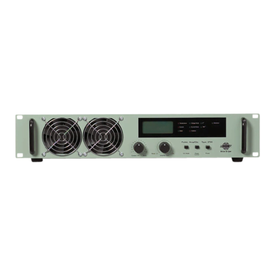
Chapter 2 Controls Front Panel Fig.2.1 Front panel of Type 2720 Display: The display shows output AC current and voltage on a LCD screen. • The Temperature LED Indicator lights red if the Power MOS Output Transistors overheat. The amplifier will then go into Reset state •... -
Page 9: Back Panel
Power Amplifier Type 2720 – User Manual • Voltage Mode: Provides constant voltage characteristics independent of changes of test object on the exciter. Gives the best acceleration waveform and is therefore preferable for most vibra- tion tests • Current Mode: Provides constant current characteristics, keeping the generated force inde- pendent of changes of test object. -
Page 10: Operation
Rack Mounting Power Amplifier Type 2720 can be used free standing on its four rubber feet. Its design also allows it to fit nicely in a 19-inch standard rack system with the rubber feet removed. - Page 11 Power Amplifier Type 2720 – User Manual Fig.3.1 Typical system setup using Type 2720 Optional 9-pin Sub-D Signal from Female to HR10 DC Static Centering Generator Cable Unit 1056 AQ 0654 4825 Serial Cable Coaxial Cable Drive Cable AQ 0649...
- Page 12 Mains Voltage Setting Type 2720 can be powered from a 100 V, 120 V or 230 V ±10% (50 to 60 Hz), single-phase AC mains supply. To select the correct mains voltage setting, use a small screwdriver to remove the...
-
Page 13: Operating Procedure
Power Amplifier Type 2720 – User Manual Mains Socket Connection Once the mains voltage setting and fuse are correct, use the power cable provided to connect the mains to the mains input socket of the amplifier. Note, that for maximum operating safety the protective (green/yellow) conductor of the cable should be connected to a suitable earth, such as the earth contact of a mains outlet socket. - Page 14 CHAPTER 3 Operation Warning Lamps and Fault Detection If one of the red warning lamps lights up, a fault has occurred in the system. Under such circumstances, the test is automatically stopped to protect the amplifier and exciter. To help establish the cause of the shutdown, some probable faults are given in the table below.
- Page 15 Power Amplifier Type 2720 – User Manual...
-
Page 16: Characteristics
Characteristics Signal Inputs The signal inputs of Type 2720 have a minimum input impedance of 10 kΩ. The AC signal input is for connecting an exciter controller or generator and is capacitive-coupled giving a – 0.5 dB lower limiting frequency of approximately 15 Hz. The DC signal input is direct-coupled enabling a DC offset voltage to be applied for centring the exciter armature. - Page 17 100k Frequency (Hz) 010203 The power output of Type 2720 is direct-coupled. Its output impedance, shown in Fig.4.1, depends on the feedback setting selected using the V/C Mode switch. Fig.4.2 Maximum output current rating of Type 2720 as a function of frequency 11.25A...
-
Page 18: Frequency Response
V/C Mode switch, as shown by the response curves for small signals given in Fig.4.3. Fig.4.3 Frequency response of Type 2720 in Voltage Mode for small power output levels Low Impedance DC Input Specification Limit DC Input... - Page 19 Power Amplifier Type 2720 – User Manual Distortion The percentage of harmonic distortion produced by Type 2720 is shown in Fig.4.4. Considering the 500 VA power output rating of the amplifier, the amount of distortion is very low. This can be attributed to the generous amount of feedback applied and the use of a direct-coupled input.
-
Page 20: Specifications
Chapter 5 Specifications COMPLIANCE WITH STANDARDS FREQUENCY RESPONSE compliance with EMC Directive Typical small signal response (–20 dB) in low- impedance mode: compliance with EMC Requirements of DC Input: DC to 15 kHz ±0.5 dB; DC to 150 kHz ±3 dB Australia and New Zealand AC Input: 15 Hz to 15 kHz ±0.5 dB (2 separate BNC sockets on rear panel) - Page 21 Power Amplifier Type 2720 – User Manual Phase (0° or 180°) POWER REQUIREMENTS Single phase 100, 120, 230 V RMS, ±10%, 50 – 60 Hz. MULTIFUNCTION DISPLAY (LCD) Approx. 1000 VA at full load Voltage, RMS, read-out accuracy ±5%, ±2 digit, 40 Hz...
-
Page 22: Service And Repair
Chapter 6 Service and Repair Type 2720 is designed and constructed to provide many years of safe, reliable operation. How- ever, if the correct function or operating safety of the instrument is impaired, immediately disconnect it from the mains source and secure it against unintended operation. For repair contact your local Brüel &... - Page 23 Power Amplifier Type 2720 – User Manual...
- Page 24 HEADQUARTERS: DK-2850 Nærum · Denmark · Telephone: +45 4580 0500 · Fax: +45 4580 1405 · www.bksv.com · info@bksv.com Australia (+61) 2 9889-8888 · Austria (+43) 1 865 74 00 · Brazil (+55)11 5188-8161 · Canada (+1) 514 695-8225 China (+86) 10 680 29906 · Czech Republic (+420) 2 6702 1100 · Finland (+358) 9-521 300 · France (+33) 1 69 90 71 00 Germany (+49) 421 17 87 0 ·...
Need help?
Do you have a question about the 2720 and is the answer not in the manual?
Questions and answers