
Related Manuals for Electrolux EPPWA060


Summary of Contents for Electrolux EPPWA060
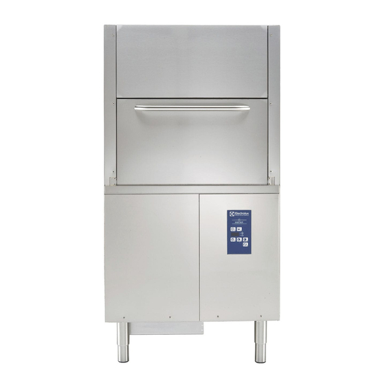
- Page 1 Pot Washer EPPWA060 Installation and operating manual * 59566V700- 2020.06 *Original instructions...
- Page 2 Installation diagram 1374...
- Page 3 HWI = Hot water Inlet pipe ⌀=3/4″ G EQ = Equipotential screw D = Drain outlet XD = Inlet pipe for detergents EI = Electrical Inlet XR = Inlet pipe for rinse-aid...
- Page 4 Foreword The installation, use and maintenance manual (hereinafter Manual) provides the user with information necessary for correct and safe use of the machine (or “appliance“). The following must not be considered a long and exacting list of warnings, but rather a set of instructions suitable for improving machine performance in every respect and, above all, preventing injury to persons and animals and damage to property due to im- proper operating procedures.
-
Page 5: Table Of Contents
Contents A SAFETY INSTRUCTIONS ........................7 General safety ..........................7 B GENERAL INFORMATION ........................7 Introduction ..........................7 General safety instructions ......................7 Additional indications........................7 Definitions........................... 7 Machine and Manufacturer‘s identification data ................... 8 Appliance identification ........................8 B.6.1 How to identify the technical data.................... 8 B.6.2 How to interpret the factory description .................. - Page 6 K MACHINE CLEANING AND MAINTENANCE..................... 22 Machine cleaning ........................22 End of service and daily cleaning ....................22 K.2.1 Clean the tank ........................22 K.2.2 Clean the nozzle jets......................23 K.2.3 Clean the wash pump filter ....................24 K.2.4 Clean the exterior surfaces....................24 Maintenance ..........................
-
Page 7: Asafety Instructions
The following symbols are Manufacturer Electrolux Professional SpA or any other used in the manual to indicate and identify service centre authorised by Electrolux Professional SpA. the various types of hazards:... -
Page 8: Machine And Manufacturer's Identification Data
Nominal 9.9 kW Electrolux Professional spa - Viale Treviso, 15 Electrolux Professional spa - Viale Treviso, 15 - 33170 Pordenone (Italy) The dataplate gives the product identification and technical data; listed below is the meaning of the various information given on it. -
Page 9: Copyright
• 1 = large (1552 mm) compliance with regulations in force in the country of use. Electrolux Professional SpA declines any liability for inaccur- acies contained in the manual, if due to printing or translation Copyright errors. -
Page 10: Ctechnical Data
TECHNICAL DATA Main technical characteristics Model EPPWA060 Power supply Electric Supply voltage: 400V 3N~ convertible to 230V 3~ Frequency Max. power Power absorbed as factory setting Boiler heating elements 10.5 Tank heating elements Water supply pressure 50 - 700 [bar] [0.5 - 7]... -
Page 11: Dtransport, Handling And Storage
WARNING For protection against indirect contacts (depending on the type of supply provided for and connection of earths to the equipotential protection circuit) refer to point 6.3.3 of EN 60204-1 (IEC 60204-1) with the use of protection devices that ensure automatic cut-off of the supply in case of isolation fault in the TN or TT systems or, for IT systems, the use of isolation controllers or differential current protection devices to activate automatic power disconnec- tion (an isolation controller must be provided for indicating a possible first... -
Page 12: Storage
CAUTION Storage Do not make modifications to the parts The machine and/or its parts must be stored and protected supplied with the appliance. Any missing from damp, in a non-aggressive place, free of vibrations and or faulty parts must be replaced with with room temperatures between -10℃... -
Page 13: Extraction Hood
Disposal of packing • Remove the wooden spacers "A" on the machine base unscrewing the four “M8“ screws. The packing must be disposed of in compliance with the current regulations in the country where the appliance is used. All the packing materials are environmentally friendly. They can be safely kept, recycled or burned in an appropriate waste incineration plant. -
Page 14: Plumbing Circuit
Plumbing circuit Power supply 380-400V 3N Open the power supply terminal board and insert the jumpers Pot washer with drain pump provided as follows: one jumper between terminals 2 and 4 and another between terminals 4 and 6. Using a suitable power supply cable (see C.1 Main technical characteristics table), connect the three phases to terminals 1, 3 and 5, the neutral to terminal 6 and the earth wire to the terminal... -
Page 15: E.12 "Haccp" Arrangement
E.12 “HACCP“ arrangement • If the water level in the tank is too high, the drain pump (if present) automatically activates to empty out the excess The machine is arranged for the “HACCP“ connection. water. Connect the “HACCP“ system to connector L3 on the base of IMPORTANT the machine. -
Page 16: Gcommissioning
Drain / self-cleaning cycle This button starts a drain/self-cleaning cycle. When the cycle is selected, the button indicator is lit up. COMMISSIONING Preliminary checks, adjustments and Detergent/rinse aid dispensers and operational tests prearrangements If the machine is connected to a water softener and/or a WARNING reverse osmosis system, contact the detergent supplier for a specific product. -
Page 17: Electrical Connections For Automatic Detergent And Rinse-Aid Dispensers
G.2.1 Electrical connections for automatic detergent • Connect the rinse-aid dispenser between terminals 8 and 9. and rinse-aid dispensers These connection points are live during filling of the tank and at the end of the rinse cycle for a set time (see H.2 Terminals are available on the power supply terminal board for Setting the dispensers paragraph). -
Page 18: Igeneral Safety Rules
For example, to adjust the parameter dIn, proceed as follows: 3. modify the parameter value and press the button “L“ to store the set value; 1. access the programming mode; 4. to exit the programming mode, press the “Wash cycle 3“ 2. -
Page 19: Instructions For Use And Maintenance
Instructions for use and maintenance • placing in the machine any objects or things not compatible with its use, or that can damage the machine, cause injury Risks mainly of a mechanical, thermal and electrical nature or pollute the environment; exist in the machine. -
Page 20: Jnormal Machine Use
Residual risk Description of hazardous Residual risk Description of hazardous situation situation Electrocution Contact with live parts during Tipping of loads When handling the machine or the maintenance operations carried packing containing it, using unsuit- able lifting systems or accessories out with the electrical panel powered or with the unbalanced load... -
Page 21: Operation
– Wash cycle “Infinite“ Cycle duration Wash cycle Type of load (sec) This button is used to start a continuous wash that does not stop until the operator selects an automatic cycle. Wash cycle 3 This cycle is recommended for very dirty pots with dried For heavily soiled residuals, pots with particular shapes or for specific user items... -
Page 22: Type Of Racks
• Close the door and select the suitable wash cycle. J.7.3 Rack for tray • The corresponding indicator light comes on and the wash cycle starts. Type of racks J.7.1 Green rack For 12 bowls with maximum diameter of 240 mm. J.7.2 Basket for pots and pans MACHINE CLEANING AND MAINTENANCE... -
Page 23: Clean The Nozzle Jets
• Remove the door by pulling it outward, making sure it does • After a few minutes, 3 beeps indicate the end of the not get stuck. cleaning cycle and “END“ blinks on the display: • Switch off the dishwasher by pressing On/Off button. •... -
Page 24: Clean The Wash Pump Filter
• Carefully clean the washing and rinse jets and clean • The internal tube of the peristaltic rinse aid and detergent everything with hot water and neutral detergent/detersive, dispenser must undergo periodical maintenance (once or if necessary using a soft brush or sponge. In particular, for twice a year). -
Page 25: Waste Storage
WARNING competent bodies in the country where scrapping takes place. In general, the appliance must be taken to a specialised Work on the electrical equipment collection/ scrapping centre. must only be carried out by The symbol on the product indicates that this specialised personnel, with the product should not be treated as domestic power supply disconnected. -
Page 26: Alarms
Alarms NO WATER • Check that the tap is open. • Check that the water inlet filter is clean. • Check the minimum mains pressure. • Check that the overflow pipe is inserted (only for appliances without drain pump). INEFFICIENT DRAINAGE •... - Page 28 Electrolux Professional SPA Viale Treviso 15 33170 Pordenone www.electroluxprofessional.com...
Need help?
Do you have a question about the EPPWA060 and is the answer not in the manual?
Questions and answers