
Related Manuals for Elenos ETG 2000.20


Summary of Contents for Elenos ETG 2000.20
- Page 1 ETG 2000.20 ETG 1000.10 ETG 500.5 ETG 150 ETG 20 FM SOLID STATE TRANSMITTER WITH AUDIO CHANGEOVER OPTION Rev. 02 − 16/12/2019 Cod. MAN1046UUK USER MANUAL...
- Page 2 Elenos USA 2561 NW 74th Ave, Unit A−16, 33122 Miami (Florida), Ph +1 855−305−3058 We kindly recommend you to fill in the RMA module (ITA http://www.elenos.com/it/ elenos−rma/ o ENG http://www.elenos.com/elenos−rma/) and to report the apparatus serial number (available on identification label).
- Page 3 Revision history Date Description (dd/mm/yy) 01/12/2017 First release 26/06/2018 Updated para 6 “Datasheet” 16/12/2019 Updated model range Revision...
- Page 4 Index Informative letter ..........Personnel in charge .
- Page 5 ..........5.1.1 ETG 2000.20 .
- Page 6 Index...
-
Page 7: Table Of Contents
........Dear Customer, Thank you for choosing an Elenos product. ELENOS s.r.l. produces solid state VHF/FM sound broadcasting transmitters ranging from minimum power of 10W to maximum power of 30kW, exchange units, remote control units, etc. -
Page 8: Personnel In Charge
In case the Customer detects a failure under warranty, he must give immediate written notice to Elenos Srl and send the product at his own expense to the Elenos Srl hea- dquarter or to the nearest qualified Elenos Srl centre; in case of shipment to its hea- dquarter, the latter agrees to replace within the next 45 days for free the defective component;... -
Page 9: Exclusion
Elenos Srl or by its aut- horized distributors, or by a use of the product other than those intended for the same pro- duct, or from any action or fact attributed to third parties who have access to the product for the same Customer’s approval or even without the Customer being aware thereof after... - Page 10 Informative letter...
-
Page 11: Safety
2 Safety Safety ............Safety precautions . - Page 12 Safety...
-
Page 13: Safety Precautions
All ELENOS s.r.l products are compliant with the safety standards required for this type of equipment. 2.1 Safety precautions The user must follow also the safety precautions listed below: D The original configuration of the equipment must absolutely not be modified. On receipt of the same equipment it is essential to check whether the supply is compliant with the order’s specific terms and in case of nonconformities please report it immedi-... - Page 14 The equipment is directly connected to the “building installation” Between the equipment and the “building connection” there is an interposed structure To ensure a correct use of the equipment do not obstruct the ventilation grids. Do not put the equipment close to heat sources, flammable products, or inside closed installations lacking of a proper air circulation.
-
Page 15: First Aid
2.2 First aid This paragraph does NOT represent a complete guide about first aid procedures, it is rather intended as a brief summary to be used as a reference. It must be in fact an impel- ling duty for all the personnel operating with this equipment to be capable of performing appropriate first aid procedures in order to prevent avoidable deaths. -
Page 16: If The Victim Is Responsive
fig.c1 C) Circulation (fig. c1): D check the victim’s pulse (fig. c1) D if absent, start cardiac massage (fig. c2) D compress the chest every 1.5 − 2 seconds D if a rescuer is present, perform 15 compressions in approximately 80 seconds, + 2 quick blows D if there are two rescuers, perform 5 compressions in approximately 60 seconds, + 1 fig.c2... - Page 17 Provide a protected under load disconnector (circuit breaker or fuses) with appropriate disconnection power and capacity according to the absorption characteristics of the equipment model. Use cables of an appropriate size with respect to the rated absorbed current. Earth connection must be performed according to the applicable laws. Special care must be applied to the earth connection of the antenna system since it is exposed to electrical atmospheric events.
-
Page 18: Exposure Evaluation
2.4 Exposure evaluation Exposure assessment requires the identification of electric field values in places where the presence of people may occur. The field values must refer to the type of stay and the exposed subjects, according to the provisions of current legislation. The identification of the electric field values can be carried out in various ways, depen ding on the need for precision and the fact that one intends to perform a prediction, or a subsequent verification. - Page 19 In the specific case of broadcasting plants for sound and television broadcasting, the fol- lowing recurrent characteristics can be found: a. the source is not isotropic, so the ERP should be calculated in the direction of the evalua- tion point b.
-
Page 20: Electric Field Values (V/M) As A Function Of Power (W) And Distance
2.4.1.1 Electric field values (V/m) as a function of power (W) and distance. Safety... - Page 21 3 CE conformity CE conformity ..........CE conformity .
- Page 22 Safety...
- Page 23 3.1 CE conformity For fi rst immission on the market, ELENOS s.r.l respects the procedures envisaged by the 1999/5/EC Directive. This includes the following: D Technical documentation available exclusively to the Control Authority for 10 years after the launch on the market of the last equipment produced for that type.
- Page 24 CE conformity...
- Page 25 CE conformity...
- Page 26 It shows the key features equipment, such as: manufacturing company, product model, power supply type and power consumption. Warning: do not ever remove this label. 3.2.2 Assistance label It shows the main Elenos customer assistance contacts. Note: this label may not be present.
-
Page 27: Product Description
4 Product description Product description ......... Controls and connections overview . - Page 28 Product description...
-
Page 29: Controls And Connections Overview
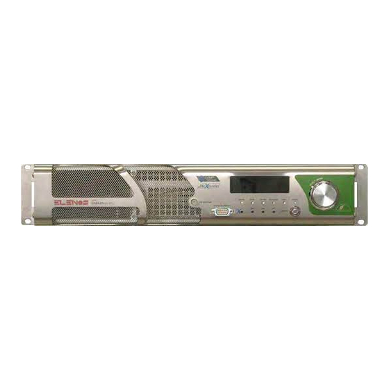
4.1 Controls and connections overview Below, the list of connections and controls available in all the product line. The differen- ces between the two rear panels shown, concern only the number of fans and the type of RF output connector. Front panel controls and connections 1) Rf monitor 5) Status LEDs... -
Page 30: Contnectors Pin Assignment
4.2 Contnectors pin assignment 4.2.1 EIA485 − Telemetry − Ethernet − Interlock EIA485 (DB9) − Cn no. 21, 2 Ethernet Connect. (EJ45) − Cn no. 19 Pin. # Function Note Pin. # Function Function EIA485/422 Tx− EIA485/422 TD− RD− EIA485/422 n.c. -
Page 31: Stereo L/R − Aes/Ebu
4.2.3 Stereo L/R − AES/EBU Stereo L/R (XLR) − Cn no. 11 AES/EBU (XLR) − Cn no. 14 Pin. # Function Type Note Pin. # Function Type Note Common Common Input L/R + Bal. Input + Diff. 600Ω/10kΩ 110Ω Input L/R − Bal. Input −... -
Page 32: Safeness Algorithms
4.3 Safeness algorithms The apparatus is provided with a hardware and software protective system which is partly integrated and partly optional. 4.3.1 Software’s protections 4.3.1.1 IPF (Intelligent Proportional Foldback) The IPF is an intelligent system which reduces the equipment’s output power in case of excess of load mismatch, thus preventing the equipment turning off. - Page 33 Current Management on the power supply (Lifextender)R This is activated when the maximum current rated for continuous operation of the power supply is exceeded. This value is lower than deliverable current limit and represents the threshold which can be exceeded only for short periods (maximum 1 minute each time). If this situation occurs, the “PSU current derating”...
- Page 34 Product description...
- Page 35 5 Block diagrams Block diagrams Block diagram 5.1.1 ETG 2000.20 5.1.2 ETG 1000.10 5.1.3 ETG 500.5 / ETG 150 5.1.3 ETG 20 Block diagram...
- Page 36 Block diagram...
- Page 37 5.1 Block diagram 5.1.1 ETG 2000.20 FINAL STAGE FINAL STAGE 3−WAY FM 2−WAY FM 3−WAY FM 3−WAY FM SPLITTER COMBINER COMBINER COMBINER DRIVER RF IN RF OUT L. P. FILTER L. P. FILTER & & DIR. COUPLER DIR. COUPLER RF SECTION...
- Page 38 5.1.2 ETG 1000.10 FINAL STAGE 2−WAY FM 2−WAY FM SPLITTER COMBINER RF IN L. P. FILTER RF OUT & DIR. COUPLER RF SECTION MAINS INPUT 220VAC board (on rear panel) FINAL L. P. MODULATOR RF OUT FILTER RF MONITOR −12 VDC +5 VDC SWITCHING PWR SUP...
- Page 39 5.1.3 ETG 500.5 ETG150 MAINS INPUT 220VAC board (on rear panel) RF AMP L. P. MODULATOR RF OUT FILTER RF MONITOR −12 VDC +5 VDC SWITCHING PWR SUP +12 VDC AC/DC CONV POWER SUPPLY SECTION 5.1.4 ETG 20 MAINS INPUT 220VAC board (on rear panel)
- Page 40 Block diagram...
-
Page 41: User Instructions
6 User instructions User instructions ..........User interface . - Page 42 Managing the device in local mode. Navi gating the menus and setting the para meters. Status LEDs and messages. Messaging. The equipment can send messages regarding status, events and alarms. The list can be consulted locally on a display, remotely via PC connected in telemetry to the front panel or via web.
-
Page 43: User Interface
6.1 User interface All commands and data displayed by screen are listed on next pages. Warning: The screens shown below are subject to change without notice and may look some different depending on system configuration. Note: for information about the remote control via web interface, please refer to the relevant “WEB interface User Manual”... -
Page 44: Menu Tree
6.1.1 Menu tree TX CONTROL PANEL MAIN WINDOW SYSTEM MENU SOLUTION LOCAL REMOTE INPUTS MENU D To scroll the menu, rotate the encoder. RF & POWER MENU D To enter a submenu, or to access the masks, press it. D To return to the main menu, press and PASSWORD MENU hold the encoder. -
Page 45: Tx Control Panel (Main Window)
6.1.2 TX Control Panel (Main Window) Main settings Main levels Target power Operating frequency VU meter area (*) Forward power Reflected power Target audio level (L) Target audio level (R) (*) The number of bars displayed depends on the type of input selected. Up to three bars can be shown: MPX (M), Left Stereo (L) and Right Stereo (R). -
Page 46: System Menu ! System Config (1 Of 2 And 2 Of 2)
6.1.3 System Menu ! System Config (1 of 2 and 2 of 2) SYSTEM MENU Temperature Unit: CELSIUS or FAHRENHEIT. Show Display: ALWAYS = display on also in remote mode. Power Oscillation Check: TRUE = RF power swing protection active. Please, note that UPS Target (W): Target power in case of functioning with UPS. -
Page 47: System Menu ! Communication Port Set / System Info
6.1.4 System Menu ! Communication Port Set / System Info SYSTEM MENU Front and rear RS485 communication ports speeds and addresses. Currently, default speed values are 38400. Previously, they were 9600. All devices working in combined or n+1 systems must be set to the same communica- tion speed, otherwise they won’t work properly. -
Page 48: System Menu ! System Time / Clock Pwr Target 1 Of 2
6.1.5 System Menu ! System Time / Clock Pwr Target 1 of 2 SYSTEM MENU In this screen it’s possible to set the current date “dd/mm/yy” and the current time “hh:mm:ss”, together with the day of the week “wd”. It’s important to set all the parameters correctly to make the adjustment algori- thms work well. -
Page 49: System Menu ! Clock Pwr Target 2 Of 2 / Telemetry Config
6.1.6 System Menu ! Clock Pwr Target 2 of 2 / Telemetry Config SYSTEM MENU Here it’s possible defining the power profiles for hours and days of the week. Each hour can be associated to any target available (T3 to T0), defined at the previ- ous step. -
Page 50: Inputs Menu ! Base Band Levels / Change Over Inputs
6.1.7 Inputs Menu ! Base Band Levels / Change Over Inputs INPUTS MENU Display−only screen. Values of the inputs and deviation for the carriers are shown. This mask may look different depending on the equipment operating mode. Displaying VU−meter style bars, located on the right of numeric values, facilitates the evaluation of the parameters. -
Page 51: Inputs Menu ! Input Sensitivity Settings
6.1.8 Inputs Menu ! Input Sensitivity Settings INPUTS MENU “Audio Mode” & AUTO sts The option “Left = Right:” set to “TRUE” forces both L and R Stereo inputs to the same attenuation level, otherwise each stereo channel is attenuated by the level sto- red in “LeVel R”... -
Page 52: Rf & Pwr Menu ! View Tx Parameters (1 Of 2 And 2 Of 2)
6.1.9 RF & PWR Menu ! View TX Parameters (1 of 2 and 2 of 2) RF & PWR MENU Display−only screen. The following data are grouped here: (On the left) operating frequency; selected profile; deviation level; device effi- ciency; counter of ROS protection occurred; working hours (on air) and fan work- ing hours. -
Page 53: Password Menu ! Password / Password Setting
6.1.10 Password Menu ! Password / Password Setting PASSWORD MENU Factory preset password is “0000”. This value must be changed in “Password set- ting” by system administrator in order to prevent unauthorized accesses. There are two levels of protection: “User” and “System”. Once the settings the two new passwords, access to menu items and parameter changes will be governed by individual privileges. -
Page 54: Password Menu ! Password Recovery
Password Menu ! Password Recovery 6.1.11 PASSWORD MENU If users forgot the password, it’s kindly advised to contact Elenos. The ”UNLOCK CODE” is useful to obtain the 24h “PASSWORD RECOVERY” and must be provided to Elenos. Subsequently, system administrator have to redefine passwords by “PASSWORD SETTING”... -
Page 55: Alarm Menu ! Alarm List / Event History
Alarm Menu ! Alarm List / Event History 6.1.12 ALARMS MENU Display−only screen. It’s possible scrolling the list of all recently occurred alarms. The ones preceeded by letter “A” are active, the others are occurred. Between brackets, the type of message is specifyed: Status,Warning and Alarm. In order to understand the meaning of the alarms please see the paragraph “Alarms/ events listing”. -
Page 56: Alarm Menu ! User Alarm Data / User Alarms Timers
Alarm Menu ! User Alarm Data / User Alarms Timers 6.1.13 ALARMS MENU Parameters of some alarms may be customized. They are: Environmental Temperature (C or F); RFTemperature (C or F); RFCur- rent(A); PSU Temperature(C or F); PSU Current(A); Forward power(W) and Reflected power(W). -
Page 57: Alarm Menu ! Audio Trim And Alarms
Alarm Menu ! Audio Trim and Alarms 6.1.14 ALARMS MENU In the box on the right, at the top of the screen, model of board and firmware installed are indicated. This mask summarizes some parameters already seen in “Input sensitivity settings” and “Change over inputs”... -
Page 58: Diagnostic Menu ! Uart 0 Info / Uart 1 Info
Diagnostic Menu ! UART 0 Info / UART 1 Info 6.1.15 DIAGNOSTICS MENU Display−only screen. This screen shows the status of the serial communication with the Hostlink Slave and the number of errors that occurred from the beginning. DIAGNOSTICS MENU Display−only screen. -
Page 59: Diagnostic Menu ! Uart 2 Info
Diagnostic Menu ! UART 2 Info 6.1.16 DIAGNOSTICS MENU Display−only screen. This screen shows the status of the serial communication with the power supply units and the number of errors that occurred from the beginning. User instructions... - Page 60 User instructions...
-
Page 61: Alarms/Warnings/Status List
6.2 Alarms/Warnings/Status list A task called “Alarms Managing” monitors all physical and logical quantities. Each of them is sampled and processed by a combinatorial network to evaluate if an alarm (or a warning) must be activated. This task and the ALC management have the same high priority for having a constant monitoring of the entire apparatus and intervene quickly. - Page 62 List of events that may be reported by the equipment. They are of 3 kinds: “STATUS” = possible statuses of the machine; “WARNING” = reports not requiring immediate tech- nical intervention; “ALARM” = faults requiring repair. Some may be different depending on equipment (see brackets in “Message”). Event Code Message...
- Page 63 Event Code Message Description One or more PSU are in thermal derating so PSU LOW POWER that the RF output power is reduced. The RF section has been turned off so that the PSU RF OFF fans can quickly cool the apparatus. WORKING MODE COMBINED The apparatus works in a combined Tx.
- Page 64 Event Code Message Description PSU MAINS OVER VOLTAGE Mains voltage too high. PILOT PWR GOOD The RF input power level is correct. (Amplifier) EXT REF MISSING External reference (10Mhz) absent. (Exciter) INCREASE PILOT PWR The RF input power level is to low but not dan- (Amplifier) gerous and must be increased.
-
Page 65: External Connectable Devices
6.3 External connectable devices 6.3.1 Connecting to a LAN/PC Connect the apparatus to PC via LAN using a switch or any other device such as a router. Also the direct connection between apparatus and PC is possible. See web connection manual for all details. EXCITER SWITCH ETH CABLES... -
Page 66: Connecting To A Change Over/Audio Matrix
In N+1 systems, the apparatus may be a transmitter or the reserve (the exciter and its connections aren’t shown). Examples of connections between these devices are shown below. Echos6 SE Tx1 in a N+1 system (Elenos Changeover) EXCITER Reserve in a N+1 Echos6 SE (Elenos Changeover) -
Page 67: Datasheet
........7.2.1 ETG 2000.20 ......... . -
Page 68: Datasheet
OLED Adjustments By front panel/via web interface Number of RF power LDMOS See “Spec” table, no. MOSFETs column RF power technology (by Elenos) ICEFET and ECOSAVING Number of power supplies Dimensions (rack units/ W−H−D) 2HE/ 48.5−8.5−58.5 cm (19.1−3.3−23 inches) Weight See “Spec”... - Page 69 Asynchronous AM S/N unweighted > 55 dB Synchronous AM S/N unweighted > 50 dB Modulation frequency range 16 Hz − 15 kHz $ 0.1 dB (with/without pre−emphasis) @ f Amplitude/frequency characteristic = 400Hz, 16Hz−15kHz L/R/Mono channel Stereo crosstalk > 60 dB (linear/non linear) @ 30Hz−15kHz L/R channel (100% modulation) Distortion <...
-
Page 70: Individual Models Specific Parameters
7.1.1 Individual models specific parameters “SPEC” table in datasheet Model Rated FWD no. MOSFETs Weight Consumption Current ETG20 20 adjustable 7.9 kg (17.4lb) 0.26A @ 230V ETG150 150 adjustable 9.4 kg (20.7lb) 230W 1A @ 230V ETG500 500 adjustable 9.4 kg (20.7lb) 570W 2.5A @ 230V ETG1000 1000 adjustable... -
Page 71: Etg Models Layouts
7.2 ETG models layouts 7.2.1 ETG 2000.20 AC/DC Main Pwr Supply Stereo coder DC/DC Pwr Supply Output directional coupler AC/DC Service Pwr supply Output filter TC/TS + Profiles boards Output combiner Interlock board Final stages Backup battery Input splitter Aux + telemetry boards Driver stage Audio inputs change−over... -
Page 72: Etg 1000.10
7.2.2 ETG 1000.10 AC/DC Main Pwr Supply Stereo coder DC/DC Pwr Supply Output directional coupler AC/DC Service Pwr supply Output filter TC/TS + Profiles boards Output combiner Interlock board Final stages Backup battery Input splitter Aux + telemetry boards Driver stage Audio inputs change−over Datasheet... -
Page 73: Etg 500.5 / Etg 150
7.2.3 ETG 500.5 ETG 150 AC/DC Main Pwr Supply AC/DC Service Pwr supply Output directional coupler TC/TS + Profiles boards Output filter Interlock board Final stage Backup battery Audio inputs change−over Aux + telemetry boards Stereo coder Datasheet... -
Page 74: Etg
7.2.4 ETG 20 AC/DC Main Pwr Supply AC/DC Service Pwr supply Output directional coupler TC/TS + Profiles boards Output filter Interlock board Final stage Backup battery Audio inputs change−over Aux + telemetry boards Stereo coder Datasheet... - Page 75 8 Maintenance Maintenance ..........Maintenance .
- Page 76 8.1 Maintenance 8.1.1 Periodic checks and replacements CHECKS Periodicity Recommended when Needed under Intervention used under extreme normal condi- conditions (tempera- tions ture, humididty, dust, reflected power) 2−weekly monthly Cleaning the air filters (if arranged on board of the unit) monthly 6−monthly Cleaning the front panel grid...
Need help?
Do you have a question about the ETG 2000.20 and is the answer not in the manual?
Questions and answers