
Subscribe to Our Youtube Channel
Related Manuals for Elenos INDIUM Series


Summary of Contents for Elenos INDIUM Series
- Page 1 INDIUM SERIES (the list is in the manual) SOLID STATE FM TRANSMITTER Rev.01- 22/04/2011 Cod. MAN1001UUK USER MANUAL...
- Page 2 (in On line Support page) Please, always you give us information about the device serial number (shown on the identifying label). Elenos s.r.l. declares that the equipment in this documentation complies with 1999/05/CE Directive. 0470 For details see “CE Conformity” Section.
- Page 3 Revision N° Date Description 17/09/2010 First release Changes of various kind: images, analog output scale values , datasheet, 22/04/2011 alarm list. Revision...
- Page 4 Family variants Transmitter Number of internal Number of RF driver Maximum output RF power amplifier power modules ETG 1600.3 3 (type BLF578) Full power 1600W ETG 1500.3 maximum output ETG 1400.3 power limited to ETG 1200.3 the nominal value ETG 1000.3 ETG 900.3 ETG 800.3 ETG 700.3...
- Page 5 Transmitter Number of internal Number of RF driver Maximum output RF power amplifier power modules ETG 800.1 1 (type BLF578) Full power 800W ETG 700.1 maximum output ETG 600.1 power limited to ETG 500.1 the nominal value ETG 400.1 ETG 300.1 ETG 250.1 ETG 200.1 ETG 150.1...
- Page 6 Index 1 Information note ........................9 1.1 Operating Staff ........................9 1.2 Responsibility ........................10 1.3 Warranty .......................... 10 1.4 Jurisdicion ........................10 2 CE conformity .......................... 11 3 Security ............................ 13 3.1 Precautions ........................13 3.2 First aid ..........................15 3.2.1 Treatment of electrical burns ...................
- Page 7 5.6.1.2 IPC (Intelligent Power Control) ................. 31 5.6.1.3 Safety Management (option “Lifextender”) ® ........... 31 5.6.2 Hardware protections ....................32 5.7 Options ..........................33 6 How to active .......................... 35 6.1 Antenna connection ......................35 6.2 Essential connections to operation .................. 35 6.3 Mains connection/disconnection ..................
- Page 8 7.1.31 Enable Alarms SMS ....................56 7.1.32 User Alarms Data ....................56 7.1.33 User Alarms Timers ....................56 7.1.34 Uart 0 Info, Uart 1 Info, Uart 2 Info ................ 57 7.1.35 SMS Enable/-3dB Alarm ..................59 7.1.36 GSM Field/String Id ....................59 7.1.37 Phone N.1 ..
-
Page 9: Operating Staff
Dear Customer, thank you for choosing an Elenos product. Elenos s.r.l. realizes solid state Transmitters for broadcasting radio in the VHF FM ranging from a minimum power of 10W to a maximum of 30kW, Exchange Unit, Remote Control Units, etc.. -
Page 10: Warranty
1.2 Responsibility Elenos is not responsible for damage or injury to objects or to people if caused by improper procedures or actions conduced by users not sufficiently trained or without experience. Descriptions and illustrations contained in this publication are not binding: without... - Page 11 2 CE conformity Elenos follows, to the marketing of all its products, the Directive 1999/5/CE. This means: • Technical fi le, made available, exclusively at the Control Authority, for 10 years after the last sale on the market of that product type. This fi le contains the product de- scription, drawings, wiring diagrams, circuits, etc.., standard and technical solutions...
- Page 12 LIST OF COUNTRIES WHERE THIS APPARATUS CAN BE USED ◊ ◊ ◊ ◊ ◊ ◊ ◊ ◊ ◊ ◊ ◊ ◊ ◊ ◊ ◊ ◊ ◊ ◊ ◊ ◊ ◊ ◊ ◊ ◊ ◊ ◊ ◊ ◊ ◊ ◊ AUTHORIZATION IS REQUIRED TO USE THIS EQUIPMENT CE conformity...
- Page 13 3 Security Elenos products meet the safety standards required for this type of equipment. 3.1 Precautions However, the user must also observe the precautions listed below: • Original equipment configuration must not be altered. Upon receipt it you must check that it correspond to the order and in case of non-compliance you must im- mediately inform Elenos.
- Page 14 The device is directly connected to the “building installation” Among the device and “building installation” there is a structure interposed • To ensure a correct function you must not obstruct the fans. Do not place the unit near heat sources, near flammable materials, or in closed installations without pro- per air circulation.
-
Page 15: First Aid
3.2 First aid This paragraph is NOT a complete guide to first aid procedures, but only a summary that can be used as a reference. It is the responsibility of all personnel who use this equipment to be ready to admini- ster adequate first aid and thus prevent avoidable loss of life. -
Page 16: Station Features
C) Circulation (fig. c1) : fig.c1 • check the heart beat (fig. c1) • in the absence of a heart beat, start cardiac massage (fig. c2) • press the sternum every 1.5 - 2 seconds • if there is one first aider, perform 15 compressions in about 80 seconds and 2 quick respirations. - Page 17 The earth connection must be implemented according to current standards. Particular attention must be used to grounding of the antenna system, because it is exposed to atmospheric electrical phenomena. Remember that despite the ground link it is always dangerous to operate on the apparatus in case of bad weather, with the presence of lightning;...
- Page 18 Security...
-
Page 19: General Information
0W up to the maximum rating (see “Family variants“ section), using in FM band between 87.5 and 108MHz at 10kHz steps. The new Indium series, this is his name, stands for new lines, new colors, an innovative look, and especially new technology, designed to outstanding performance. - Page 20 “Identification and Quick Start” manual, which should be kept at station, always attached to the product; • n°1 “User” manual; • n°1 CD containing the documentation; • n°1 cable to PC connection. Cables, spare parts and other accessories can be obtained by Elenos or Elenos dealers. General information...
-
Page 21: Product Description
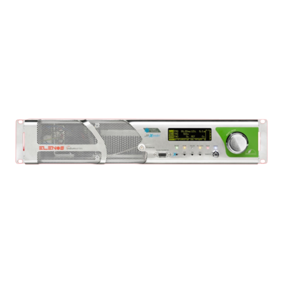
5 Product description 5.1 Marks and labels location and type 1 INDIUM SERIES ® – Transmitter series name. Indium series indicates the range of devi- ces that use the precious metal indium. Indium has adaptability and thermal conductivi- ty properties, with benefits of exchange efficiency that remain unchanged in an infinite time. -
Page 22: Front Panel
5.2 Front panel 1 OLED display – graphic display that shows operative parameters and functions selec- ted by encoder. 2 Encoder – multi-function knob that allows to see functions menu and to modify opera- tive parameters: • SELECT HIGHLIGHTED ITEM_short pressure of the knob; •... -
Page 23: Rear Panel
EIA485 standard. 7 RF Monitor connector – BNC connector to connect external measuring devices, it allows the measure of low level RF signal (0dBm full scale). Warning: this monitor is not calibrated, so a perfectly constant output level, with frequency, is not guaranteed. It must NOT used to measure the output power, nor to measure harmonic components. -
Page 24: External Connectors Description
7 AUX inputs – BNC connectors for channel modulating auxiliary input (RDS/SCA). 8 MPX input – BNC connector for the stereo modulating compound signal input. 9 Monitor/19kHz OUT connector – output connector, BNC type, to monitor MPX, RDS or SCA signals, or to extract 19kHz signal of stereo subcarrier to synchronization. Set by hardware (jumper JP3). - Page 25 5.4.2 LEFT/RIGHT connectors N° 5 Rear panel (XLR Female) Connector Description Note J01 on board TG- Common ground 3K1A866 or J1 on board TG3K2A867 Audio signal right Differential input channel “+” Audio signal right channel “-” J02 on board TG- Common ground 3K1A866 or J2 on Audio signal left...
- Page 26 “Closed to ground” status → Warning active F_TC_ALRM_RST Reset allarms Pin connected to ground = command active Spare pin Reserved Elenos F_DTM_FWD_PWR Analog voltage output direct power (see 5.4.7.1 paragraph) Common ground F_RX+ EIA485 Product description...
- Page 27 F_TX+ EIA485 Common ground F_DTM_V_PA Analog voltage output voltage Power Amplifier (see 5.4.7.1 paragraph) F_TS_FLT_AUDIO Allarm FAULT audio Pin must be exter- nally powered. open collector “Closed to ground” status → Alarm active F_TS_/FLT Allarm FAULT Pin must be exter- nally powered.
- Page 28 5.4.8 Profiles connector (option) N° 11 Rear panel (DB25 Female) Connector Description Note CN1 on board TeleControl input Max voltage 0V..24V TG2U2A899 channel 1 (0V..12V) TeleControl input Max voltage 0V..24V channel 3 (0V..12V) TeleControl input Max voltage 0V..24V channel 5 (0V..12V) TeleControl input Max voltage 0V..24V reserve channel...
- Page 29 5.4.9 TCP/IP - Reserved connectors N° 12 Rear panel (RJ48) Connector Description Note CN3 on board ETHERNET connector TG2U2A899 CN2 on board Common ground TG2U2A899 Segnale TX- Standard EIA485 (0..5V) Segnale TX+ Segnale RX+ Standard EIA485 (0..5V) Segnale RX- Common ground Interlock Signal Type Open Col- lector without protec-...
- Page 30 5.5 Technical brochure GENERAL DATA Output Nominal Power (@230V) 1600W adjustable (ETG 1600.3) (N.B. @ 115V Singlephase the output nomi- 1200W adjustable (ETG 1200.2) nal power remains constant except for ETG 800W adjustable (ETG 800.1) 1600.3 and ETG 1200.2 where a derating of 150W adjustable (ETG 150) the maximum output power may occur) 30W adjustable (ETG 30)
-
Page 31: Software Protections
5.6 Protections The device has a protection system, partly integrated and partly optional, related to har- dware and software. 5.6.1 Software protections 5.6.1.1 IPF (Intelligent Proportional Foldback) IPF is an intelligent system that reduces the output power in case of unbalanced load avoiding shutdown. -
Page 32: Hardware Protections
from power supply. The condition of current derating is turned off when the power supplied back to the va- lue set by the user and if the maximum current supplied from power supply is less than or equal to the maximum allowable value for continuous operation. Thermal management on power supply (Lifextender) ®... - Page 33 5.7 Options ETG models can be purchased with options : Input modulating signal Option Purchase information version model code BASE 00E-OAX-10 (ETG 1600.3) 00E-PAX-10 (ETG 1200.2) Inputs: 00E-QAX-10 (ETG 800.1) • 00E-RAX-10 (ETG 150) • Aux 1 TC/TS 00E-OAX-15 (ETG 1600.3) Outputs: 00E-PAX-15 (ETG 1200.2) 00E-QAX-15 (ETG 800.1)
- Page 34 Product description...
-
Page 35: Antenna Connection
6 How to active 6.1 Antenna connection To connect the RF output connector to the antenna cable (to test the performance of the apparatus can be connected to a dummy load capable to consume the power supplied from the apparatus). 6.2 Essential connections to operation fig.a In case of option TC/TS, to check for the interlock jumper (fig.a). -
Page 36: Factory Settings
Now to connect the power cord into an outlet suitable: the device automatically turns on in standby mode. Warning: don’t deliver RF power before you have connected the device to the antenna. 6.4 Factory settings The device leaves the factory with the following default settings. If they match with the needs of the user simply to set the desired power and place the device in RF ON. -
Page 37: Frequency Setting
6.5 Main parameters setting More detailed information can be found in “Use instructions” (User Manual). To set the main parameters (frequency, power, and audio level) put the key switch in LOCAL mode (blue LED lit). The window for setting appears automatically. The parameters shown are the following: 1 Leds (left side) •... -
Page 38: Power Setting
Press the encoder to confirm. The window now shows the new working frequency. 6.5.2 Power setting To set the power, rotate the encoder up to highlight the field “power”. Press once to enter the window of power regulation. The field “power” is now highlighted and editable: rotate clockwise/counterclockwise, respectively, the encoder to increase/decrease the output power. -
Page 39: Audio Level Setting
6.5.3 Audio level setting To move the cursor to the field “LEV”, and press the encoder to make it editable. Rotare the encoder to turn down the amplification (-15dB). Apply the desired audio signal (as indicated in the next paragraph). Increase slowly the gain until the Vu-meter reach the 0 dB level in accordance with the audio signal peaks. - Page 40 6.5.4.2 MPX To use an MPX signal, select this mode by moving the cursor on the display and press the encoder to confirm. Apply the MPX signal to the BNC connector on rear panel. 6.5.4.3 STEREO To use a STEREO signal, select this mode by moving the cursor on the display and press the encoder to confirm.
- Page 41 6.5.4.4 MONO To use a mono signal, select this mode on the display by turning the encoder and press to confirm. Apply the signal to the connector XLR MONO/RIGHT on rear panel. The audio signal can be both balanced and unbalanced. In the latter case there is a reduction of 3dB level.
- Page 42 How to active...
-
Page 43: User Interface
7 Use instructions 7.1 User interface In “How to active” section is described the main window “Status and Settings” that ap- pears automatically when you turn on the unit in local mode. Here it is given the steps to set the main parameters (frequency, power, level and type of audio signal). This section goes into details, to inspect all the control and setting interfaces. - Page 44 7.1.1 Status and Settings It’s the main window that appears automatically when you turn on the device in local mode. In it are displayed and can be modified the operating parameters. More details are given in “Main parameters setting” paragraph in “How to active” sec- tion.
-
Page 45: Alarms List
SFETs), PSUs temperature, and the fan speed (expressed as a percentage of nominal value). The unit of temperature can be set in this menu, choosing between Celsius and Fahrenheit. PSU Temperature RF Temperature Environment Temperature 7.1.6 Alarms List List of last 16 alarms. Those marked with the letter “A” is still active at that time. For more detail, please see “Alarms/events list”paragraph. - Page 46 7.1.8 RF Data Temperatures and currents of each RF modules are displayed. 7.1.9 PSUs Data The following parameters, related to power supply, are displayed : voltage, current, temperature. From here you can “force” the ON/OFF status through the ENABLE flag in FALSE/TRUE. Use instructions...
- Page 47 Exciter Menù Menu Exciter Inputs Level Aux Inputs Level Pilot Level & Phase Exciter Clipping Alarms Audio Settings AES/EBU Settings Time Base Profile Summary 1 of 2 Profile Summary 2 of 2 Exit Use instructions...
- Page 48 7.1.10 Inputs Level From here you can set the audio levels. This mask differs depending on the selected mode (MONO, STEREO, MPX or MUTE). In STEREO or MUTE mode, where both input channels are active, there is a flag that for- ces the two gains to be equal.
- Page 49 7.1.14 Alarms Audio Settings From there you can set these audio alarms: • alert in case of audio absence • alert in case of overmodulation. In the first case should be set to the threshold of sound the time for which it must veri- fy the condition.
- Page 50 7.1.18 Profile Summary 2 of 2 It is the second screen which shows the status profiles. The parameters displayed are: audio level, clipping presence or absence, and voltage reference. Use instructions...
- Page 51 System Menù Menu System Pre Amplifier Voltages System Info System Time Clock Pwr Target Max Reflected Power Comm.ID LC/RT Disp.mode Password Setting Password Recovery Special Settings Foldback Setting Com1 Speed Set Enable Alarms Sms User Alarms Data User Alarms Timer Menu Uarts Menu Uarts…...
-
Page 52: System Info
7.1.19 Pre Amplifier Control menu (reserved) related to the preamplifier, read-only mode. 7.1.20 Voltages It displays the power supplies voltages, with a comparison between nominal and actual values. 7.1.21 System info It is given indication on the software version, protocol version, operating time of the equipment, operating time of the fans. -
Page 53: Clock Pwr Target
7.1.23 Clock Pwr Target Besides standard adjustment of the power it is possible set the power in time slots, in order to save the energy. To set the power in time slots it must be inhibited the option that makes fixed the power for the entire period of 24 hours. To move the cursor on “TRUE”, making it editable. - Page 54 7.1.24 Max Reflected Power The maximum reflected power allowable is 10% of rated output. From here you can set a lower value. Warning: in this case is not guaranteed correct operation of foldback. 7.1.25 COMM. ID LC/RT DISP. MODE From here you can set the guidelines and activate the display so that the menus remain displayed even with the REMOTE mode.
-
Page 55: Password Recovery
If you forget your password you can contact Elenos. You must provide to Elenos the “Unlock Code”, in this screen. Elenos provides a password for a period of 24 hours to be included in this screen in the “Password Recovery”. Then you must define a new pas- sword in “Password Setting”. - Page 56 7.1.30 COM1 SPEED SET In this screen you can set the port speed (we recommend setting the value to 9600.) 7.1.31 Enable Alarms SMS In addition to a “state” alarm management it can also be used an “event” manage- ment. Alarms for which you enable this mode of management are put into a buffer.
- Page 57 7.1.34 Uart 0 Info, Uart 1 Info, Uart 2 Info Control menu (reserved) for testing the serial ports, read-only mode. Use instructions...
- Page 58 GSM Menù Menu GSM SMS Enable / -3dB Alarm GSM Field / String Id Phone N. 1 Phone N. 2 Phone N. 3 Phone N. 4 Phone N. 5 SMS Diagnostic Exit Use instructions...
- Page 59 7.1.35 SMS Enable/-3dB Alarm In this screen you can enable sending -3dB alarm through SMS, that is no longer active to overcome the 2/3 of the power set. Set here the name of the station in “String ID”. 7.1.36 GSM Field/String Id It can be displayed in this screen, the field strength of the GSM signal and set an alarm in the absence of electricity for a time period set.
- Page 60 7.1.39 Password Some of the items described above are confidential and are only visible under authori- zations enjoyed by the user. From this screen you can enter the password. 7.1.40 Exit To exit by the sub menu and go to the next level. Use instructions...
-
Page 61: Alarms/Events List
7.2 Alarms/events list There is an “Alarms Management” module. To check the alarm conditions physical and logical digital inputs are used. Each input status is sampled and then the condition is logically drawn by a combinato- rial network, to define if the alarm or signal are active. Response time is 100ms minimum. - Page 62 “022 PSU THERMAL FAULT” It indicates a power supply overheating resul- ting turning off the machine. In the case of Elenos equipment with more than one power supply this protection is intended to allow reduced power operation if one power supply has been disconnected for hardware protec- tion from excessive temperature.
- Page 63 “039 USER PSU TEMP OUT LIMIT” It indicates a deviation from the conditions to set by user in relation to power supply temperature. “040 USER RF CURRENT OUT LIMIT” It indicates a deviation from the conditions to set by user in relation to RF modules currents. “041 USER PSU CURRENT OUT LIMIT”...
- Page 64 7.4 Optional equipment can be connected ETG may be connected externally to the following units: • • TELEMETRY; • EXCHANGE UNIT and/or AUDIO MATRIX UNIT; • AMPLIFIERS. 7.4.1 PC connection This connection is useful to examine in detail the operating parameters, for example during the performance evaluation or repair activities.
- Page 65 To Verify that the other masks on Hyper Terminal contain the settings as below. Confirm by pressing the “OK”. At the end, activate the connection by pressing the Call button. Use instructions...
- Page 66 To communicate with the equipment you need to make a final step, to put the address. This step is crucial because each device, to be queried and managed remotely, must be properly addressed. In this case, the following alpha-numeric sequence must be put: 2 1 i x x.
- Page 67 7.4.2 Telemetry connection This connection allows remote control through the equipment specifically designed for that purpose. The telemetry unit provides backup energy for the continuous opera- tion of the modem, and is equipped with all utilities for equipments and station para- menters supervision.
- Page 68 Connection mode if TX no reserve Exciter Echos6 Connection mode if TX re- serve and no audio matrix Exciter Echos6 Use instructions...
-
Page 69: Amplifier Connection
Exciter Connection mode if TX reserve and audio matrix Matrix Echos6 7.4.4 Amplifier connection This connection is where you need to increase the power transmission using a RF power amplifier. To use the ETG as an exciter of a higher power amplifier to connect the ETG RF output connector to amplifier RF input connector through a RF coaxial cable, which is capable of withstanding the maximum power of ETG. - Page 70 Connection mode Exciter Amplifier Use instructions...
-
Page 71: Maintenance
8 Maintenance To details, please ask the Service Manual to Elenos. 8.1 Spare parts The available spare parts list is as follows: (unless otherwise specified the component is in every ETG model) • 2LC00011 FILTER 115/250V 3A WITH RESISTANCE •... - Page 72 • 1VENT037 FANS 80X80X38 24Vdc 1,65A 39,6W PAPST (ETG MODELS : ETG1600.3 - ETG800.1 - ETG150) • 1VENT027 FANS 80X80X38 24Vdc SANYO-DENKI (ETG MODELS : ETG1200.2) • EPSU3KWPZ001/EPSU2K5PZ001 POWER SUPPLY 3KW/2.5KW (ETG MODELS : ETG1600.3 - ETG 1200.2) • EPSU1KW0PZ001/ EPSU1KWPZ001 POWER SUPPLY 1KW 42V 24A/1KW 50V 20A (ETG MODELS : ETG800.1 - ETG150) •...
- Page 73 • 2PCB0512 COMBINER (ETG MODELS : ETG1600.3) • 2PCB0529 COMBINER (ETG MODELS : ETG1200.2) • 2PCB0523 JUNCTION (ETG MODELS : ETG800.1) • TG2U0A899 CPU BOARD • TG2U1A899 TC/TS BOARD (OPTION) • TG2U2A899 CHANNEL BOARD (OPTION) • TG2U4A899 QUADRUPLE POWER SUPPLY BOARD (ETG MODELS : ETG1600.3 - ETG 1200.2) •...
- Page 74 • TG2UCA890 SPLITTER BOARD+MEASURE POINT (ETG MODELS : ETG1200.2) • TG2UAA899 LP FILTER+MEASURE POINT (ETG MODELS : ETG1600.3 - ETG1200.2) • TG2UBA890 LP FILTER+MEASURE POINT (ETG MODELS : ETG800.1) • TG1 3A111 LP FILTER+MEASURE POINT (ETG MODELS : ETG150) • TG3K0A866 STEREO CODER BOARD (OPTION) •...
- Page 75 8.2 Maintenance (cleaning, replacement, con- trol) During normal operation periodic inspections are recommended, in order to verify the absence of critical operating conditions. It is recommended to adopt the following program: Frequence Type of maintenance 15 days To clean filter (very dusty environment). 30 days To clean filter (slightly dusty environment).
- Page 76 8.3 Malfunction (effects, causes and solutions) Effect Cause Solution Transmitter does not turn on • Power cord defective or • Replace the cable or con- missing nect to apparatus • Auxiliary power incor- • Call the manufacturer rect (MAINS LED on front panel off) •...
- Page 77 Address incorrect • Set the correct address metria/PC • Connection cable not • Verify that the cable used suitable is that provided by Elenos or an equivalent • Parameters setting incor- • Check correct pa- rect rameters in “Use instructions”section, “Op- tional equipment can be connected”(user manual)
- Page 78 Maintenance...
Need help?
Do you have a question about the INDIUM Series and is the answer not in the manual?
Questions and answers