
Subscribe to Our Youtube Channel
Related Manuals for Elenos ETG5200


Summary of Contents for Elenos ETG5200
- Page 1 ETG5200 ETG3500 ETG2500 (list of variations available in the manual) SOLID STATE FM TRANSMITTER Rev. 01- 27/08/2013 Cod. MAN1008UUK USER MANUAL...
- Page 2 Elenos s.r.l. declares that the equipment described in this document is compliant with the 1999/05/EC Directive. 0470 For details please refer to the “EC Marking” section. All rights reserved. No part of this manual can be reproduced in any form without prior written authorization from Elenos S.r.l.
- Page 3 EC Declaration of Conformity According to Directive 1999/5/EC (R&TTE) We : ELENOS s.r.l. - via G.Amendola, 9 – 44028 Poggio Renatico (FE) - Italy Declare under our sole responsibility that the product: ETG5200, ETG5000, ETG4000/5, ETG3500/5, ETG3000/5, ETG2500/5, ETG2000/5, ETG1800/5, ETG1500/5, ETG1200/5, ETG1000/5, ETG800/5, ETG500/5 ETG3500, ETG3000/3.5, ETG2500/3.5, ETG2000/3.5, ETG1800/3.5, ETG1500/3.5, ETG1200/3.5, ETG1000/3.5,...
- Page 5 Revisions No. Date Description 02/04/2012 Original version Validity for ETG3500-ETG2500 transmitters Warranty management reference User interface section update 27/08/2013 Alarm list update Add transmitter internal photos Power supply dip-switch setting procedure Revisions...
- Page 6 Series models Transmitter Number of modules Number of drivers Maximum output power ETG5200 5200W ETG5000 5000W ETG4000/5 Equal to the rated ETG3500/5 value ETG3000/5 ETG2500/5 ETG2000/5 ETG1800/5 ETG1500/5 ETG1200/5 ETG1000/5 ETG800/5 ETG500/5 ETG3500 3500W ETG3000/3.5 Equal to the rated ETG2500/3.5 value ETG2000/3.5...
-
Page 7: Table Of Contents
Contents 1 General information ........................9 1.1 Intended use ........................9 1.2 Transport ..........................9 1.3 Unpacking .......................... 9 1.4 Storage ..........................9 1.5 Decommissioning and disposal ..................10 1.6 Checking the product purchased ..................10 2 Product description ......................... 11 2.1 Description of external connectors .................. - Page 8 3.4.1.1 Hyperterminal interface ................... 53 3.4.2 Connection to telemetry ..................65 3.4.3 Connection to exchange unit and/or audio matrix ..........66 3.4.4 Connection to Elenos E.BOX module ................ 68 4 Maintenance ........................... 69 4.1 Device overview ......................69 4.2 Settings ..........................73 4.2.1 Power supply Dip-switch ..................
-
Page 9: General Information
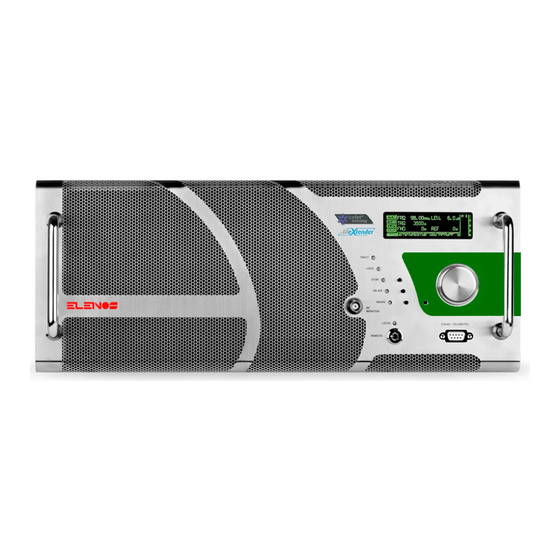
0W to a maximum rated value (see Section “Series models”), to be used in the whole FM band between 87.5 and 108 MHz, in 10 kHz steps. With this product, Elenos has achieved its aim of obtaining high values of power in just 4 rack units. -
Page 10: Decommissioning And Disposal
It may also contain: • n°1 “User” manual; • n°1 CD containing all the documentation relative to Elenos s.r.l. manuals; • n°1 PC connection cable. Cables, spare parts and other accessories may be requested from Elenos S.r.l. or Elenos retailers. General information... -
Page 11: Product Description
2 Product description [10] You can find a detailed description of section here flagged in the Quick Start manual. Product description... - Page 12 [11] [10] [12] [13] [14] [7] [8] You can find a detailed description of section here flagged in the Quick Start manual. Product description...
-
Page 13: Description Of External Connectors
2.1 Description of external connectors 2.1.1 EIA485 connector/Telemetry N. 6 Front panel (type DB9 - female) This connector uses Com1, as the connector n. 13 (rear). The two connectors can’t be used simultaneously. Connector Meaning Notes CN3 on board Com1 TX+ EIA485/422 TG5K2A881 Com1 TX-... -
Page 14: Aux Connectors
2.1.4 AUX connectors N. 7 Rear panel (BNC type - female) Connector Meaning Notes J2 on board RDS/SCA AUX1 Input TG3K0B866 Common ground J3 on board AUX2 Input TG3K0B866 Common ground 2.1.5 MPX connector N. 8 Rear panel (BNC type - female) The input signal on the connector is in parallel, inside the card, to the signal L + right channel. -
Page 15: Tc/Ts Connector
2.1.7 TC/TS connector N. 10 Rear panel (DB25 type - female) Signals compatible with standard IEC 60864-1. As reported here applies both to the signals TC/TS that for the signals PROFILES. • Digital I/O • Polarity N • Maximum voltage range: 0 to +30 V •... - Page 16 Reset alarm Command pulse Pin grounded = active command UPS target Command to state Reserved for Elenos Forward power Output in voltage See full scale values Common ground Connected to the frame Com2 EIA485/422...
-
Page 17: Full Scale Values
Bad audio Signaling output The pin must be po- open wered externally. collector “Closed to ground” status → Active alarm /FLT (reversed pola- Signaling output rity) The pin must be po- open wered externally. collector “Open” Status → Acti- ve alarm The operation can be affected by the set- tings of the machine... -
Page 18: Profiles Connector
2.1.8 Profiles connector N. 11 Rear panel (DB25 type - female) Connector Meaning Notes CN1 on boardT- Channel 1 Command pulse G2U2A899 Channel 3 Command pulse Channel 5 Command pulse Riserve Command pulse Common ground Connected to the frame Common ground Connected to the frame Not connected... -
Page 19: Tcp/Ip Connectors - Reserved
2.1.9 TCP/IP connectors - Reserved N. 12 Rear panel (RJ48 type) Connector Meaning Notes CN3 on board ETHERNET interface TG2U2A899 10Base-T or 100Base- CN2 on board Reserved TG2U2A899 2.1.10 EIA485 connector N. 13 Rear panel (DB9 type - female) This connector uses Com1, as the connector n. 6 (front). The two connectors can’t be used simultaneously. -
Page 20: Technical Data Sheet
2.2 Technical data sheet FM TRANSMITTER MEDIUM POWER | ETG5000 Datasheet GENERAL DATA Output Nominal Power 5000 W adjustable Operating band 87.5 ÷ 108 MHz RS232/RS485 Yes. Connector DB9 female Points of measure RF Sample - MPX Monitor Displayed Parameters More than 50 parameters displayed on a wide graphic 0-LED screen Adjustments... - Page 21 FM TRANSMITTER MEDIUM POWER | ETG5000 Asynchronous AM S/N unweighted > = 55 dB a 400 Hz, 75 us de-emphasis Synchronous AM S/N > = 50 dB a 400 Hz, 75 us de-emphasis Amplitude-frequency characteristic +/- 0.1 dB (without pre-emphasis) (stereo/mono operation) +/- 0.1 dB (with pre-emphasis) 20 Hz to 15 KHz, @ 400hz...
- Page 22 FM TRANSMITTER MEDIUM POWER | ETG3500 Datasheet GENERAL DATA Output Nominal Power 3500 W adjustable Operating band 87.5 ÷ 108 MHz RS232/RS485 Yes. Connector DB9 femate Points of measure RF Sample - MPX Monitor Displayed Parameters More than 50 parameters displayed on a wide graphic OLED Adjustments From the frontal panel through OLED/from PC...
- Page 23 FM TRANSMITTER MEDIUM POWER | ETG3500 Asynchronous AM S/N unweighted > = 55 dB a 400 Hz, 75 us de-emphasis Synchronous AM S/N > = 50 dB a 400 Hz, 75 us de-emphasis Amplitude-frequency characteristic +/- 0.1 dB (without pre-emphasis) (stereo/mono operation) +/- 0.1 dB (with pre-emphasis) 20 Hz to 15 KHz, @ 400 Hz...
- Page 24 FM TRANSMITTER MEDIUM POWER | ETG2500 Datasheet GENERAL DATA Output Nominal Power 2500 W adjustable Operating band 87.5 ÷ 108 MHz RS232/RS485 Yes. Connector DB9 female Points of measure RF Sample - MPX Monitor Displayed Parameters More than 50 parameters displayed on a wide graphic OLED Adjustments From the frontal panel through OLED/from PC...
- Page 25 FM TRANSMITTER MEDIUM POWER | ETG2500 Asynchronous AM S/N unweighted > = 55 dB a 400 Hz, 75 us de-emphasis Synchronous AM S/N > = 50 dB a 400 Hz, 75 us de-emphasis Amplitude-frequency characteristic +/- 0.1 dB (without pre-emphasis) (stereo/mono operation) +/- 0.1 dB (with pre-emphasis) 20 Hz to 15 KHz, @ 400 Hz...
-
Page 26: Protections
2.3 Protections The equipment has a protection system which is partially integrated and partially optio- nal both for the hardware and the software. 2.3.1 Software protections 2.3.1.1 IPF (Intelligent Proportional Foldback) The IPF is an intelligent system which reduces the equipment’s output power in the event of strong load mismatch, thus preventing the machine from turning off. - Page 27 Current management on the power supply (Lifextender) ® This is activated when the maximum current for continuous operation of the power sup- ply is exceeded. This value is set below the deliverable current limit and constitutes the threshold which can be exceeded only for short periods (maximum 1 minute at a time). Should this situation arise, the “PSU current derating”...
-
Page 28: Hardware Protections
2.3.2 Hardware protections The hardware protection system comprises: • fast electronic and fuse protection of power supplies; • fast electronic protection on the fan power supply; • fast protection against excess reflected power (SWR/VSWR) following a strong load mismatch. This protection is activated when the reflected power value exceeds 10% of the direct one. -
Page 29: Instructions For Use
3 Instructions for use 3.1 User interface The controls and display views are described below. Please note that in order to have complete visibility of all the available interfaces, the equipment must be set to LOCAL mode and it must be accessed with the specific passwords. - Page 30 TX CONTROL PANEL SYSTEM CONFIG GSM AND MODEM SERVICE PROFILE RF/BASEBAND MODE SYSTEM CONFIG 1 PHONE N.1 TO 4 PROFILE BASEBAND LEVELS AUDIO TRIM & ALRM PHONE N.5 TO 8 VIEW TX PARAMETERS 1 COMMUNICATION PORT SET EXIT SYSTEM INFO VIEW TX PARAMETERS 2 SYSTEM TIME BASEBAND LEVELS...
-
Page 31: Tx Control Panel
3.1.1 TX control panel Main screen which appears automatically when turning on in LOCAL mode. It is used to set and check the main operating parameters. Vu-meter: it must indicate approx. 0dB Warning light: when Target audio level Target frequency it is on it indicates the opening of the interlock contacts. -
Page 32: Profile Rf/Baseband Mode
3.1.2 Profile RF/Baseband mode Setting and display screen. For every profile, the frequency, target power, type of audio signal and pre-emphasis are defined. The active profile values are indicated by the letter “A”. The deviation is displayed (in kHz). 3.1.3 Profile baseband levels Setting and display screen. -
Page 33: View Tx Parameters 1
3.1.4 View TX parameters 1 Display only screen. The parameters which can be monitored are as follows: frequency, active profile num- ber, deviation, efficiency, transmitter working hours, fan working hours, direct power target, effective direct power value, reflected power, current, voltage, maximum tem- perature (the following pictures show the probe position) and fan speed. -
Page 34: Baseband Levels
3.1.6 Baseband levels Setting and display screen. There are levels of the audio signal. The display changes depending on the audio mode selected. 3.1.7 Alarms list Display only screen. It is possible to monitor the list of most recent alarms. The alarms indicated by the let- ter “A”... -
Page 35: Password
If you lose your password, please contact Elenos. Elenos must be given the “Unlock code” in this screen. Elenos will provide a password valid for 24 hours to be entered on the same screen under the “Password Recovery” item. The user must later define new passwords through the “Password Setting” screen. -
Page 36: System Config
(PAbias), maximum settable power full scale (Max Target Pwr). 3.1.12.1 Power oscillation algorithm In Elenos devices, if there is a power variation of “n” W (“n” being defined in specific tables) at least 3 consecutive times within 15 seconds, the “035” alarm is activated and the three block out mechanism is triggered (if this mechanism fails, the “003”... -
Page 37: System Config 1
3.1.13 System config 1 Setting and display screen. The alarm signal, caused by wrong output power, snaps by default at -3dB of target power and disappears when you reach the 2/3 of that. The “Min Level Fwr Pwr Fault” additional parameter, set here, acts in an AND condition with the standard algorithm: so, the alarm will snap when there is the first between the two conditions “-3dB”... -
Page 38: Audio Trim & Alrm
3.1.14 Audio trim & alrm Setting and display screen. The following parameters can be set by the user: pilot tone level, pilot tone phase, clipping voltage. It is possible to monitor the audio board model (BB board model, automatically detected, or STEREO view as default) and the firmware version of the audio board (BB Firmware). -
Page 39: Communication Port Set
3.1.15 Communication port set Setting and display screen. The parameters which can be set by the user are the speed and the front and rear 485 door addresses. 3.1.16 System info Setting and display screen. The equipment software version, the protocol version, the equipment activity time and the fan operating time are indicated. -
Page 40: Clock Pwr Target
3.1.18 Clock Pwr Target Setting and display screen. As well as the standard power adjustment, it can also be set according to time slots in order to save energy. In order to be able to set the power according to individual time slots, the field “Target Power Mode”... -
Page 41: Enable Alarms Sms
3.1.19 Enable Alarms Sms Setting and display screen. Besides the alarm management “by status”, it is possible to have alarm management “by event”. The alarms for which this management mode is enabled merge in a buffer. If the value “0” is attributed to the relative alarm, it means that is deactivated, while the value “1”... -
Page 42: User Alarms Data
3.1.21 User Alarms Data Setting and display screen. Some alarms can be set according to activation conditions. The current value of the alarm condition parameter (ambient temperature, RF tem- perature, RF current, power supply temperature, power supply current, direct power, reflected power) can be monitored. -
Page 43: Lifextender
Setting and display screen. The parameters relative to the Lifextender option can be monitored: equipment serial number, equipment code (parameter to be notified to Elenos should the user require the activation/deactivation of this function), activation/deactivation code (parameter supplied by Elenos to be entered for the function activation/deactivation), function sta- tus, work days in good operating conditions, work days in critical operating conditions. -
Page 44: Gsm And Modem Service
3.1.24 GSM and modem service Setting and display screen. The GSM signal field intensity can be monitored. It is possible to enable the submission of an alarm by SMS and/or PSTN in case of no mains power (No Mains SMS) for the period of time set (Delay). It is possible to enable the submission of an alarm by SMS and/or PSTN if the power delivered is at least 3dB less than the target set (SMS FWD over 2/3). -
Page 45: Uart 0,1,2 Info
3.1.26 Uart 0,1,2 info Control menu for testing the serial ports. 3.1.27 SMS diagnostic To see the number of SMS sent and received successfully. For more detail see paragraph “SMS List”. Instructions for use... -
Page 46: Alarms/Events List
3.2 Alarms/events list There is an “Alarm management” module. In order to check the alarm conditions, physical and logical digital inputs are used. The status of each input is sampled and the condition is then logically processed by a combinational network so as to establish whether the alarm or signalling is active. The minimum intervention time is 100ms. - Page 47 “022 PSU THERMAL FAULT” This indicates power supply overheating with subsequent switching off of the machine. For ELENOS equipment with more than one power supply, the intervention of this protection aims to allow operation at reduced power, should a power supply be disconnected to protect the hardware from excessive tempe- rature.
- Page 48 “039 USER PSU TEMP OUT LIMIT” This indicates a variation with respect to the conditions set by the user relating to the power supply temperature. “040 USER RF CURRENT OUT LIMIT” This indicates a variation with respect to the conditions set by the user relating to the RF module currents.
-
Page 49: Sms List
3.3 SMS list 3.3.1 SMS commands (submit) It is possible to submit SMSs in order to perform the following commands: Command SMS text Setting power to xxxxx PWR xxxxx Setting the equipment to stand-by mode STBY Setting the equipment to stand-by mode Setting the equipment to On Air mode Status request Reset request... - Page 50 Exxxx ID xx SMS String +39xxxxxxxxxx Status No mains xx m NoAudio AudioOK xxx Messaggio di segnalazione FWD yyyyy W REFL yyyyy W FRQ xxx.xxMHz VDS xxx.xV IDS xxx.xxA TEMPMAX xxx.xC TEMPENV xxx.xC Exxxx ID xx SMS String +39xxxxxxxxxx Command No mains xx m NoAudio AudioOK...
- Page 51 Where : Exxxx ID xx is the description of the apparatus with indication of the ID number SMS String is a customizable string of 10 characters +39xxxxxxxxxx is the telephone number of origin of the last command STBY/ON AIR indicates (command) that the machine is in Standby (Off)/On Air -3dB Alarm indicates that the machine is working below the-3dB Status is the response to an SMS status command Command is the confirmation to a command...
-
Page 52: Externally Connectable Optional Equipment
To connect the equipment to a PC, insert an interface cable into the “Interface” connec- tor, DB9, located on the front panel of the machine. This may be supplied with the product (Elenos code CAB0068-0). The connection can also be made when the machine is operating. -
Page 53: Hyperterminal Interface
3.4.1.1 Hyperterminal interface The Hyperterminal pages have a very similar structure to the display view, hence they will not be further described herein. Since there is more available space, there could be additional parameters. Main Menù Main Menù Main RF data (M) Instructions for use... - Page 54 Main Menù Profiles (O) Main Menù Exciter monitor (E) Instructions for use...
- Page 55 Main Menù Status/Alarms (S) Main Menù Events History (H) Instructions for use...
- Page 56 Main Menù Password (K) Main Menù Password (K) Password (K) Instructions for use...
- Page 57 Main Menù Password (K) Password reset (R) Main Menù Password (K) Password settings (P) Instructions for use...
- Page 58 Main Menù System (Y) Main Menù System (Y) System settings (X) Instructions for use...
- Page 59 Main Menù System (Y) Comm. settings (U) Main Menù System (Y) Audio trim & alrm (J) Instructions for use...
- Page 60 Main Menù System (Y) Clock power set (C) Main Menù System (Y) SMS phone set (P) Instructions for use...
- Page 61 Main Menù System (Y) User warning (F) Main Menù System (Y) En. 0-31 alrm SMS (V) Instructions for use...
- Page 62 Main Menù System (Y) En. 32-63 alrm SMS (B) Main Menù System (Y) Life eXtender (L) Instructions for use...
- Page 63 Main Menù Debug (D) Main Menù Debug (D) GSM debug (G) Instructions for use...
- Page 64 Main Menù Debug (D) Uarts (F) Main Menù Debug (D) Uarts (F) Uart 0,1,2 Instructions for use...
-
Page 65: Connection To Telemetry
To connect to an external telemetry unit, insert a standard extension cable into the “EIA485” connector, DB9, located on the rear panel of the machine. This cable is supplied with the telemetry unit (Elenos code ETGSAL33). The connection can also be made when the machine is operating. -
Page 66: Connection To Exchange Unit And/Or Audio Matrix
If the system has an audio matrix, this latter cable must be connected the matrix itself and not to the exchange unit. These cables are supplied with the exchange unit (Elenos code CAB0324-0). The signal cables can also be connected when the equipment is working, exclu- ding all RF cables. - Page 67 CAB0324-0 CAB0324-0 CAB0324-0 Instructions for use...
-
Page 68: Connection To Elenos E.box Module
To connect to the E.BOX module, insert a standard extension cable into the “EIA485” connector, DB9, located on the front or rear panel of the machine. This cable is supplied with the module (Elenos code ETGSAL33). The connection can also be made when the machine is operating. -
Page 69: Maintenance
4 Maintenance 4.1 Device overview We report here the images of how, less than specific customizations, the apparatus out by the manufacturer. If necessary, refer to these to restore the configuration of the transmitter. The figures are related to ETG5000. For ETG3500 and ETG2500 the only significant diffe- rences to mention are that: •... - Page 70 CONCENTRATOR BOARD Maintenance...
- Page 71 RF MODULES Maintenance...
- Page 72 Maintenance...
-
Page 73: Settings
4.2 Settings 4.2.1 Power supply Dip-switch In this series there are three power supplies (2.5KW or 3KW). On the power supplies must set the operating mode (analog, digital), using the dip- switch SW1, and the address, using the dip-switch SW2. Switch1 Switch2 Switch3... - Page 74 POWER SUPPLIES Maintenance...
-
Page 75: Spare Parts And Mounting
4.3 Spare parts and mounting Refer to the Spare Parts manuals, technical bulletins, e-learning videos and training courses provided by the Manufacturer. 4.4 Routine maintenance (cleaning, replace- ments, checks) During normal operation, we recommend performing routine checks in order to verify that there are no critical operating conditions. -
Page 76: Operating Faults (Symptoms, Causes And Remedies)
4.5 Operating faults (symptoms, causes and remedies) Fault Cause Remedy The equipment does not start. • Faulty or missing power • Replace the power supply supply cable cable and connect it to the equipment • Auxiliary power supply • Contact the manufacturer incorrect (Led MAINS on the front panel off) •... - Page 77 • Connection cable unsui- • Check that the cable table used is that supplied by ELENOS or equivalent • Incorrect parameter • Check the correct para- setting meters and set them in the section “Instructions for use”, at paragraph...
- Page 78 Maintenance...
Need help?
Do you have a question about the ETG5200 and is the answer not in the manual?
Questions and answers