
Subscribe to Our Youtube Channel
Related Manuals for Elenos ETG5200


Summary of Contents for Elenos ETG5200
- Page 1 ETG5200 ETG5000 ETG3500 ETG2500 (list of variations available in the manual) SOLID STATE FM TRANSMITTER Rev. 02- 27/11/2013 Cod. MAN1008QUK IDENTIFICATION AND QUICK START MANUAL...
- Page 2 Elenos s.r.l. declares that the equipment described in this document is compliant with the 1999/05/EC Directive. 0470 For details please refer to the “EC Marking” section. All rights reserved. No part of this manual can be reproduced in any form without prior written authorization from Elenos S.r.l.
- Page 3 Revisions No. Date Description 02/04/2012 Original version Validity for ETG3500-ETG2500 transmitters Warranty management reference 07/05/2013 208V 2-ph mains configuration Grounding instructions for antenna system 27/11/2013 Warranty conditions Revisions...
- Page 4 Series models Transmitter Number of modules Number of drivers Maximum output power ETG5200 5200W ETG5000 5000W ETG4000/5 Equal to the rated ETG3500/5 value ETG3000/5 ETG2500/5 ETG2000/5 ETG1800/5 ETG1500/5 ETG1200/5 ETG1000/5 ETG800/5 ETG500/5 ETG3500 3500W ETG3000/3.5 Equal to the rated ETG2500/3.5 value ETG2000/3.5...
-
Page 5: Table Of Contents
Contents 1 Informative letter ........................7 1.1 Personnel in charge ......................7 1.2 Warranty ..........................8 1.3 Exclusion ..........................8 1.4 Exemption from liability ....................9 2 EC Marking ..........................11 3 Safety ............................15 3.1 Precautions ........................15 3.2 First aid ..........................17 3.2.1 Treatment of electrical burns ................... - Page 6 Contents...
-
Page 7: Informative Letter
1 Informative letter Dear Customer, Thank you for choosing an Elenos product. ELENOS s.r.l. produces solid state VHF/FM sound broadcasting transmitters ranging from minimum power of 10W to maximum power of 30kW, exchange units, remote control units, etc. The equipment has been produced to ensure constant performance over time, provided all periodic checks and simple maintenance repairs required are carried out. -
Page 8: Warranty
Elenos Srl center. All of the above is valid notwithstanding the judgment of the engineer appointed by Elenos Srl of the existence of one of the cases of exclusion from the warranty indicated above. -
Page 9: Exemption From Liability
Otherwise, should the Customer fail to observe the instructions contained in the instruc- tion manual, and the minimum diligence required of normal users of the equipment, the warranty granted by Elenos Srl shall be invalid and the Customer takes full responsi- bility for the risk and any damage suffered by the products. - Page 10 Informative letter...
-
Page 11: Ec Marking
2 EC Marking For launching all its products on the market, ELENOS s.r.l respects the procedures envisaged by the 1999/5/EC Directive. This includes the following: • Technical documentation available exclusively to the Control Authority for 10 ye- ars after the launch on the market of the last equipment produced for that type. - Page 12 EC Declaration of Conformity According to Directive 1999/5/EC (R&TTE) We : ELENOS s.r.l. - via G.Amendola, 9 – 44028 Poggio Renatico (FE) - Italy Declare under our sole responsibility that the product: ETG5200, ETG5000, ETG4000/5, ETG3500/5, ETG3000/5, ETG2500/5, ETG2000/5, ETG1800/5, ETG1500/5, ETG1200/5, ETG1000/5, ETG800/5, ETG500/5 ETG3500, ETG3000/3.5, ETG2500/3.5, ETG2000/3.5, ETG1800/3.5, ETG1500/3.5, ETG1200/3.5, ETG1000/3.5,...
- Page 13 LIST OF COUNTRIES WHERE THIS APPARATUS CAN BE USED AUTHORIZATION IS REQUIRED TO USE THIS EQUIPMENT Other types of certification are managed according to the apparatus use country. EC Marking...
- Page 14 EC Marking...
-
Page 15: Safety
3 Safety All ELENOS s.r.l products are compliant with the safety standards required for this type of equipment. 3.1 Precautions The user must follow also the precautions listed below: • The original configuration of the equipment must absolutely not be modified. Upon receipt, check that the supply is compliant with the order specifications and if not, report it to ELENOS s.r.l. - Page 16 The equipment is directly connected to the “building installation” Between the equipment and the “building connection” there is an interposed structure • To ensure its correct operation do not cover the ventilation grids on the equipment. Do not place the equipment close to heat sources, flammable products or closed installations without appropriate ventilation.
-
Page 17: First Aid
3.2 First aid This paragraph is NOT a comprehensive guide to first aid procedures; it is intended as a summary to be used as a reference. It is the duty of all staff using this device to perform appropriate first aid procedures in order to prevent avoidable deaths. -
Page 18: If The Victim Is Responsive
C) Circulation (fig. c1): fig.c1 • check the pulse (fig. c1) • if absent, start cardiac massage (fig. c2) • compress the chest every 1.5 - 2 seconds • if a rescuer is present, perform 15 compressions in approximately 80 seconds, + 2 quick blows •... - Page 19 equipment model. Use cables of an appropriate size with respect to the rated absorbed current. Earth connection must be performed according to the applicable laws. Special care must be applied to the earth connection of the antenna system since it is exposed to electrical atmospheric events.
- Page 20 2.4.1.1 Electric field values (V/m) as a function of power (W) and distance. Power transmitted Distance from the source of the evaluation point by the source (ERP) 100m 300m 500m 1,000m 3,000m 5,000m 10,000m in Watts 98.4ft 164ft 328ft 984ft 1,640ft 3,280ft 9,840ft...
-
Page 21: Product Presentation
4 Product presentation 4.1 Marks and labels 1 ICEFET ® – Design technology of RF modules that ensures high efficiency in the whole range of output powers, at very low temperatures, hence increasing the life of MOS devices. 2 LIFEXTENDER ® – Optional system within the equipment. Once operating, it allows safe operation even in extremely severe environmental conditions. - Page 22 Warning: do not remove this name- plate. 6 SUPPORT LABEL – Label indicating the details for Elenos support. 7 DISPOSAL LABEL – Label indicating that the equipment must be disposed of properly and according to the laws in force.
-
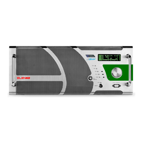
Page 23: Front Panel
4.2 Front panel 1 OLED technology display – Graphic display showing the operating parameters and selected functions my means of an encoder. 2 Encoder – Multifunction handle allowing navigation through function menus and mo- dification of operating parameters. 3 Key selector – It can be set on LOCAL (controllable through the front panel) or REMOTE (controllable through PC) mode, by rotating the key supplied with the equipment. - Page 24 [10] Product presentation...
-
Page 25: Rear Panel
4.3 Rear Panel 1 Power supply terminal board – Terminal board with 6 contacts connecting the three internal power supplies. For details of the connection mode, please refer to section “Quick guide for commissioning”. 2 Earthing screw – Eyelet for earthing the equipment, located behind the flange of the output coaxial connector. - Page 26 [11] [10] [12] [13] [14] [7] [8] Product presentation...
-
Page 27: Quick Instructions For Commissioning
• the equipment is isolated from contact with liquids. Elenos recommends the use of dehumidifiers at the transmitter site to reduce moistu- re buildup in humid climates when the transmitter is turned off for extended periods. Make sure the equipment is properly earthed. - Page 28 WARNING: the connection operations of the power supply cable to the equipment ter- minal boards must be performed with the cable UPLUGGED from the electrical mains or WITHOUT VOLTAGE exclusively. Should the operator require to disconnect the equipment from the mains, go backwards always disconnecting first the electrical plug and then removing the terminals from the terminal board.
- Page 29 The lines (L1, L2, L3) and neutrals (N1, N2, N3) of the three power supplies must be connected so that each of them is affected by a pair of different phases. Elenos recommends the use of surge suppression devices for the AC lines to prevent high voltage damage due to lighting strike near the transmitter site.
- Page 30 Quick instructions for commissioning...
- Page 31 Quick instructions for commissioning...
- Page 32 Quick instructions for commissioning...
- Page 33 Connect the desired audio cables. Insert the cable for the interlock in the TC/TS connector. If the equipment is inside an Elenos rack, connect the power supply cable to the plug on the rack and check that the electromechanical drawer is appropriately cabled.
-
Page 34: Factory Settings
5.2 Factory settings The equipment comes with the following default factory settings. If they correspond to your requirements, just put the machine in RF ON. Should you need to change the parameters, please refer to paragraph “Main parameter setup”. ETG EQUIPMENT VERSION FACTORY With Stereo Coder board (it works With Stereo Coder bo-... -
Page 35: Main Parameter Setup
5.3 Main parameter setup To set the parameters from the display the equipment must be in LOCAL mode. It is also possible to partially view the menus in REMOTE mode, provided that the para- meter “SHOW D. : ALWAYS” is present (for details, refer to the paragraph “User interfa- ce”... -
Page 36: Frequency Setup
5.3.1 Frequency setup In the “TX control panel” screen, rotate the encoder until it selects the frequency set. Press once to enter the adjustment mask. The frequency range is now selected and can be modified: rotate the encoder clockwi- se/anticlockwise to increase/decrease the value respectively. Press the encoder to confirm. -
Page 37: Power Setup
5.3.2 Power setup In the “TX control panel” screen, rotate the encoder until it selects the power set. Press once to enter the adjustment mask. The power field is now selected and can be edited: rotate the encoder clockwise/anti- clockwise to increase/decrease the value respectively. Press the encoder to confirm. -
Page 38: Audio Signal Setup
5.3.3 Audio signal setup According to the type of audio signal used to modulate, select the relative input. In the “TX control panel” screen, rotate the encoder until it selects the fifth tab of the horizontal menu. Press once to make the field editable. Then, rotate the encoder to view the available options: 5.3.3.1 MUTE Mode which mutes all inputs. - Page 39 Quick instructions for commissioning...
- Page 40 Quick instructions for commissioning...
-
Page 41: Audio Level Setup
5.3.4 Audio level setup In the “TX control panel” screen, rotate the encoder until it selects the audio level set. Press once to make the field editable. Rotate the encoder until the amplifier is at the minimum level ( - 15dB). Apply the audio signal. -
Page 42: Start-Up
5.3.5 Start-up In the “TX control panel” screen, rotate the encoder until it selects the second tab of the horizontal menu to turn it on. Press the encoder until the RFON message appears. In LOCAL mode the following must occur to have a compliant situation: •... -
Page 43: Intervention Inventory
6 Intervention inventory 6.1 Check list Check date Operation hours Description Notes Signature Check date Operation hours Description Notes Signature Check date Operation hours Description Notes Signature Check date Operation hours Description Notes Signature Check date Operation hours Description Notes Signature Check date Operation hours... -
Page 44: Maintenance Inventory
6.2 Maintenance inventory Maintenance date Operation hours Description Notes Signature Maintenance date Operation hours Description Notes Signature Maintenance date Operation hours Description Notes Signature Maintenance date Operation hours Description Notes Signature Maintenance date Operation hours Description Notes Signature Maintenance date Operation hours Description Notes... -
Page 45: Repair Inventory
6.3 Repair inventory Repair date Operation hours Description Notes Signature Repair date Operation hours Description Notes Signature Repair date Operation hours Description Notes Signature Repair date Operation hours Description Notes Signature Repair date Operation hours Description Notes Signature Repair date Operation hours Description Notes... -
Page 46: Intervention Request Sheet
The following pages report the sheets to be filled in and attached to the product should it need to be sent to ELENOS for checks and/or repairs. The correct and detailed completion of the sheet will allow us to detect the problem more quickly. - Page 47 FAILURE SHEET To be sent with the equipment to: ELENOS S.r.l. Via G. Amendola, 9 44028 Poggio Renatico (FERRARA) Italy Serial Number : Date of production : ALARMS LIST (Main Menù) - Active alarms 0) A 1) A 2) A 3) A ..
- Page 49 FAILURE SHEET To be sent with the equipment to: ELENOS S.r.l. Via G. Amendola, 9 44028 Poggio Renatico (FERRARA) Italy Serial Number : Date of production : ALARMS LIST (Main Menù) - Active alarms 0) A 1) A 2) A 3) A ..
- Page 51 FAILURE SHEET To be sent with the equipment to: ELENOS S.r.l. Via G. Amendola, 9 44028 Poggio Renatico (FERRARA) Italy Serial Number : Date of production : ALARMS LIST (Main Menù) - Active alarms 0) A 1) A 2) A 3) A ..
Need help?
Do you have a question about the ETG5200 and is the answer not in the manual?
Questions and answers