
Subscribe to Our Youtube Channel
Related Manuals for Elenos ETG 2000.20


Summary of Contents for Elenos ETG 2000.20
- Page 1 ETG 2000.20 ETG 1500.15 ETG 1000.10 ETG 700.7 ETG 500.5 ETG 300.3 ETG 150 (the list of variants is in the manual) SOLID STATE FM TRANSMITTER Rev. 01- 27/11/2013 Cod. MAN1009QUK IDENTIFICATION AND QUICK START MANUAL...
- Page 2 Transmitter N° RF modules N° driver Max output power ETG 1000.10 From 1000W to ETG 900.10 FREESCALE 80W depending of ETG 800.10 MRF6VP2006H variants ETG 700.10 ETG 600.10 ETG 500.10 ETG 400.10 ETG 300.10 ETG 250.10 ETG 200.10 ETG 150.10 ETG 100.10 ETG 80.10 ETG 700.7...
- Page 3 Transmitter N° RF modules N° driver Max output power ETG 300.3 From 300W to ETG 250.3 FREESCALE 50W depending of ETG 200.3 MRF6V4300NR1 variants ETG 150.3 ETG 100.3 ETG 80.3 ETG 50.3 ETG 150 From 150W to ETG 100 FREESCALE 10W depending of ETG 80 MRF6V2150NR1...
- Page 4 Index 1 Informative letter ........................9 1.1 Personnel in charge ......................9 1.2 Warranty .......................... 10 1.3 Exclusion .......................... 10 1.4 Exemption from liability ....................11 2 CE conformity .......................... 13 3 Safety ............................17 3.1 Precautions ........................17 3.2 First aid ..........................19 3.2.1 Treatment of electrical burns ...................
- Page 5 1 Informative letter Dear Customer, Thank you for choosing an Elenos product. ELENOS s.r.l. produces solid state VHF/FM sound broadcasting transmitters ranging from minimum power of 10W to maximum power of 30kW, exchange units, remote control units, etc. The equipment has been produced to ensure constant performance over time, provided all periodic checks and simple maintenance repairs required are carried out.
- Page 6 Elenos Srl center. All of the above is valid notwithstanding the judgment of the engineer appointed by Elenos Srl of the existence of one of the cases of exclusion from the warranty indicated above.
- Page 7 Otherwise, should the Customer fail to observe the instructions contained in the instruc- tion manual, and the minimum diligence required of normal users of the equipment, the warranty granted by Elenos Srl shall be invalid and the Customer takes full responsi- bility for the risk and any damage suffered by the products.
- Page 8 2 CE conformity For launching all its products on the market, ELENOS s.r.l respects the procedures envisaged by the 1999/5/EC Directive. This includes the following: • Technical documentation available exclusively to the Control Authority for 10 ye- ars after the launch on the market of the last equipment produced for that type.
- Page 9 LIST OF COUNTRIES WHERE THIS APPARATUS CAN BE USED AUTHORIZATION IS REQUIRED TO USE THIS EQUIPMENT CE conformity...
- Page 10 3 Safety All ELENOS s.r.l products are compliant with the safety standards required for this type of equipment. 3.1 Precautions The user must follow also the precautions listed below: • The original configuration of the equipment must absolutely not be modified. Upon receipt, check that the supply is compliant with the order specifications and if not,...
- Page 11 The equipment is directly connected to the “building installation” Between the equipment and the “building connection” there is an interposed structure • To ensure its correct operation do not cover the ventilation grids on the equipment. Do not place the equipment close to heat sources, flammable products or closed installations without appropriate ventilation.
- Page 12 3.2 First aid This paragraph is NOT a comprehensive guide to first aid procedures; it is intended as a summary to be used as a reference. It is the duty of all staff using this device to perform appropriate first aid procedures in order to prevent avoidable deaths.
- Page 13 C) Circulation (fig. c1): fig.c1 • check the pulse (fig. c1) • if absent, start cardiac massage (fig. c2) • compress the chest every 1.5 - 2 seconds • if a rescuer is present, perform 15 compressions in approximately 80 seconds, + 2 quick blows •...
- Page 14 equipment model. Use cables of an appropriate size with respect to the rated absorbed current. Earth connection must be performed according to the applicable laws. Special care must be applied to the earth connection of the antenna system since it is exposed to electrical atmospheric events.
- Page 15 4 Product presentation 4.1 Marks and labels 1 INDIUM SERIES ® – Transmitter series name. Indium series indicates the range of devices that use the precious metal indium. Indium has adaptability and thermal con- ductivity properties, with benefits of exchange efficiency that remain unchanged in an infinite time.
- Page 16 CE marking, serial number, test date, tester name. Warning: do not remove this label. 6 SERVICE LABEL – This label contains the main references for Elenos assistance. 7 DISPOSAL LABEL – This label highlights how the equipment should be disposed in an appropriate manner, in accordance with the regulations.
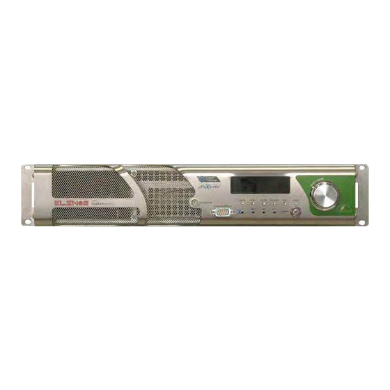
- Page 17 4.2 Front panel 1 OLED display – Graphic display that shows operative parameters and functions selec- ted by encoder. 2 Encoder – Multi-function knob that allows to see functions menu and to modify ope- rative parameters. 3 Keyswitch – It can be placed in LOCAL mode (front panel-manageable) or REMOTE mode (PC-manageable), by rotating the key supplied with the apparatus.
- Page 18 Product presentation...
- Page 19 3 Fans – Fans for cooling. Depending on the model they may be present in numbers equal to 2 or 3. 4 RF connector – Depending on power output it can be either 7/16 (ETG 2000.20, ETG 1500.15, ETG 1000.10, ETG 700.7, ETG 500.5) or N (ETG 300.3, ETG 150).
- Page 20 [14] [11] [10] [12] [13] Product presentation...
- Page 21 5 How to active 5.1 Installation If you have available a rack insert the apparatus in it and fix it. Without a rack it is important that: • apparatus has been positioned at such a distance from the walls of the room, so you can perform installation and maintenance in a comfortable way;...
- Page 22 To be sure of the proper grounding to be made at the screw located below the supply terminals and/or to the terminal referenced by the ground symbol (termi- nal yellow / green). Verify that the value of the mains voltage and the conductors used are appropriate (see Table 1), then apply the line and neu- tral wires to the power terminal block.
- Page 23 2000W 50% of consum- 8.7A 8.7A ption @230VAC, since the RF power provided @115VAC is 50% lower that @230VAC ETG 2000.20 2700W 50% of consum- 11.7A 11.7A ption @230VAC, since the RF power provided @115VAC is 50% lower that @230VAC TABLE 1 Fix the protective screen of the terminals.
- Page 24 Connect the RF output connector to the antenna cable (to test the performance of the apparatus can be connected to a dum- my load capable to consume the power supplied from the apparatus). Connect the audio cables you need. How to active...
- Page 25 In case of option TC/TS, connect the inter- lock cable. How to active...
- Page 26 If the equipment is inside a Elenos rack connect the network cable to the socket on the rack and make sure that the circuit box is properly wired. Arm the appropriate sections. The device will automatically turn on in standby mode.
- Page 27 5.2 Factory settings The device leaves the factory with the following default settings. If they match with the needs of the user simply set the desired power and place the device in RF ON. Instead, if there was a need to change the parameters, refer to “Main parameters set- ting”...
- Page 28 5.3 Main parameters setting To set the parameters to the display device must be in LOCAL mode. Instead, you can see part of the menu, even if it is in REMOTE mode, if there is the set- ting “DIP.ON REMOTE SHOW: TRUE” (for details refer to the “User Interface” paragraph). The transition from LOCAL to REMOTE there is by turning the key, supplied, in the selec- tor.
- Page 29 5.3.1 Frequency setting In Status&Settings screen rotate the encoder up to highlight the field frequency. Press once to enter in the mask for adjustment. The frequency field is now highlighted and editable: rotate clockwise/counterclockwise the encoder, respectively, to increase decrease the value. Press the encoder to confirm.
- Page 30 5.3.2 Power setting In Status&Settings screen rotate the encoder up to highlight the field power. Press once to enter in the mask for adjustment. The power field is now highlighted and editable: rotate clockwise/counterclockwise the encoder, respectively, to increase decrease the value. Press the encoder to confirm.
- Page 31 5.3.3 Audio input setting Depending on the audio signal type used to modulate, you must select the correspon- ding input. In Status&Settings screen rotate the encoder until highlight the five horizontal tab menu. Press to make the field editable. Now rotate the encoder to see other options: 5.3.3.1 MUTE Used to mute all inputs.
- Page 32 SAME PROCEDURE FOR PRE-EMPHASIS LEVEL How to active...
- Page 33 5.3.4 Audio level setting In Status&Settings screen rotate the encoder up to highlight the field LEV. Press the encoder to make it editable. Rotare the encoder to turn down the amplification (-15dB). Apply the desired audio signal. Increase slowly the gain until the Vu-meter reach the 0 dB level in accordance with the audio signal peaks.
- Page 34 How to active...
- Page 35 5.3.5 Turn on In Status&Settings screen, to turn on the unit, rotate the encoder until highlight the second tab of the horizontal menu. Press the encoder to make display the written RFON. In LOCAL mode, you have a situation of conformity where occurs that: •...
- Page 36 How to active...
- Page 37 6 Intervention register 6.1 Control register Control data Operation hours Description Note Signature Control data Operation hours Description Note Signature Control data Operation hours Description Note Signature Control data Operation hours Description Note Signature Control data Operation hours Description Note Signature Control data Operation hours...
- Page 38 ETG 2000.20 ETG 1500.15 ETG 1000.10 ETG 700.7 ETG 500.5 ETG 300.3 ETG 150 (the list of variants is in the manual) SOLID STATE FM TRANSMITTER USER MANUAL...
- Page 39 Website : www.elenos.com (in On line Support page) Please, give us information about the device serial number (shown on the identifying label). Elenos s.r.l. declares that the equipment in this documentation complies with 1999/05/CE Directive. For details see “CE Conformity” Section.
- Page 41 Family variants Transmitter N° RF modules N° driver Max output power ETG 2000.20 From 2000W to ETG 1900.20 FREESCALE 100W depending of ETG 1800.20 MRF6VP11KH variants ETG 1700.20 ETG 1600.20 ETG 1500.20 ETG 1400.20 ETG 1200.20 ETG 1000.20 ETG 900.20 ETG 800.20...
- Page 42 Transmitter N° RF modules N° driver Max output power ETG 1000.10 From 1000W to ETG 900.10 FREESCALE 80W depending of ETG 800.10 MRF6VP2006H variants ETG 700.10 ETG 600.10 ETG 500.10 ETG 400.10 ETG 300.10 ETG 250.10 ETG 200.10 ETG 150.10 ETG 100.10 ETG 80.10 ETG 700.7...
- Page 43 Transmitter N° RF modules N° driver Max output power ETG 300.3 From 300W to ETG 250.3 FREESCALE 50W depending of ETG 200.3 MRF6V4300NR1 variants ETG 150.3 ETG 100.3 ETG 80.3 ETG 50.3 ETG 150 From 150W to ETG 100 FREESCALE 10W depending of ETG 80 MRF6V2150NR1...
- Page 44 Index 1 General information ........................9 1.1 Intended use ........................9 1.2 Shipment ..........................9 1.3 Unpacking .......................... 9 1.4 Storage ..........................9 1.5 Off line and disposal ......................10 1.6 Purchased product verification ..................10 2 Product description ......................... 11 2.1 External connectors description..................
- Page 45 3.1.16 Alarms Audio Settings .................... 45 3.1.17 AES/EBU Settings ....................46 3.1.18 Time Base ....................... 46 3.1.19 Profile Summary ..................... 46 3.1.20 Pre Amplifier ......................47 3.1.21 Voltages ........................47 3.1.22 System Info ......................47 3.1.23 System Time ......................48 3.1.24 Clock Pwr Target .....................
- Page 46 1 General information 1.1 Intended use The products described in this document are solid state transmitters with an output power adjustable from 0W up to the maximum rating (see “Family variants“ section), using in FM band between 87.5 and 108MHz at 10kHz steps. The Indium series, this is its name, that already stands for new lines, new colors, an innovative look, and especially new technology designed to outstanding performance, has been further improved.
- Page 47 Indium series product; • n°1 “Identification and Quick Start” manual, which should be kept at station, always attached to the product; • n°1 “User” manual. Cables, spare parts and other accessories can be obtained by Elenos or Elenos dealers. General information...
- Page 48 2 Product description Product description...
- Page 49 [14] [11] [10] [12] [13] Product description...
- Page 50 2.1 External connectors description 2.1.1 EIA485/Telemetry connector N°[6] Front panel (DB9 Female) Connector Pin No. Signal Remark Panel board TX_1 485 filtered output Differential signal (+) /TX_1 485 filtered output Differential signal (-) RX_1 485 filtered input Differential signal (+) / RX_1 485 filtered input Differential signal (-)
- Page 51 2.1.4 AUX connectors N°[7] Rear panel (BNC Female) Connector Pin No. Signal Remark J2 or Coder RDS/SCA/AUX1 Input (RDS/SCA only with Coder Stereo Stereo board) or MPX board GND / Common Connector Pin No. Signal Remark J3 Coder Stereo board AUX2 Input GND / Common...
- Page 52 Pin must be externally powered. collector “Closed to ground” status Warning active F_TC_ALRM_RST Reset allarms Pin connected to ground = command active Spare pin Reserved Elenos F_DTM_FWD_PWR Analog voltage output direct power (see . .7.1 paragraph user manual) GND / Common F_RX+ EIA485 F_TX+...
- Page 53 ETG 1500.15 FWD pwr 1500W 1V/375W REFL pwr 150W 1V/37.5W PA current 1V/12.5A PA voltage 1V/12.5V Device Parameters Scale output fs factor ETG 2000.20 FWD pwr 2000W 1V/500W REFL pwr 200W 1V/50W PA current 1V/18.75A PA voltage 1V/12.5V Product description...
- Page 54 2.1.8 Profiles connector (option) N°[11] Rear panel (DB25 Female) Connector Pin No. Signal Remark Channel board Telecontrol input channel 0V..24V 1 (0V..12V) Telecontrol input channel 0V..24V 3 (0V..12V) Telecontrol input channel 0V..24V 5 (0V..12V) Telecontrol input channel 0V..24V riserve (0V..12V) GND / Common GND / Common Not connected...
- Page 55 2.1.9 TCP/IP - Reserved connectors (option) N°[12] Rear panel (RJ48) Connector Pin No. Signal Remark Channel board GND / Common Standard EIA485 (0..5V) Signal TX- Standard EIA485 (0..5V) Signal TX+ Standard EIA485 (0..5V) Signal RX+ Standard EIA485 (0..5V) Signal RX- GND / Common Interlock Open Collector signal without protection...
- Page 56 2.4 Options ETG models can be purchased with options : Input modulating signal Option Purchase information version model code BASE 00E-XAX-10 (ETG 2000.20) 00E-WAX-10 (ETG 1500.15) Inputs: 00E-TAX-10 (ETG 1000.10) • 00E-KAX-10 (ETG 700.7) • Aux 1 00E-SAX-10 (ETG 500.5) 00E-UAX-10 (ETG 300.3)
- Page 57 3 Use instructions 3.1 User interface In this section there is the detail tree of menu, to view all the control interfaces and the machine setting. Use instructions...
- Page 60 3.1.1 Status & Settings Main screen that appears automatically on power in LOCAL. Used to set and verify the main parameters. Vu-meter : should achieve near 0dB Target audio level Target frequency Indication : when lit in- dicates that the interlock contacts are open Indication : when lit indicates a power loss...
- Page 61 3.1.2 Audio Setting In this window you can set a range of audio parameters accessible from other menus, but that here are grouped together in order to speed up the setting. They are: frequency, type of input (“Base band mode”), the internal/external reference of the PLL (“F.ref”...
- Page 62 3.1.5 Temperatures The following parameters are shown: RF temperature (max value measured from probe on RF MOSFETs), PSU temperature (value measured from probe on power supply) and fan speed (expressed as a percentage of nominal value). The unit of temperature can be set in this menu, choosing between Celsius and Fahren- heit.
- Page 63 3.1.8 RF Data Temperatures and currents of each RF modules are displayed. 3.1.9 PSUs Data The following parameters, related to power supply, are displayed : voltage, current, temperature. From here you can “force” the ON/OFF status through the ENABLE flag. Warning : in ETG 700.7, ETG 500.5, ETG 300.3 e ETG 150 the indication of tempera- ture and ON/OFF command is not available.
- Page 64 (parameter to indicate if you want to request activation/ deactivation of the functionality at a later date), activation/deactivation code (parame- ter provided by Elenos to enter for the on/off function), status, day of work with fun- ction active, working days in critical condition.
- Page 65 3.1.14 Pilot Level & Phase To set the pilot tone level and phase. 3.1.15 Exciter Clipping To set the maximum voltage value, in order to control the overmodulation. 3.1.16 Alarms Audio Settings To set these audio alarms: • alert in case of audio absence •...
- Page 66 3.1.17 AES/EBU Settings If you have AES/EBU connection you can still choose the ANALOG operating mode throu- gh this screen, setting “Audio input mode” properly as ANALOG or AUTO. The “Current mode” value automatically adapts. 3.1.18 Time Base To set the VCO synchronization, as internal (TCXO) or external. The external reference frequency is 10,000 MHz.
- Page 67 3.1.20 Pre Amplifier Control menu related to the preamplifier. Warning : in ETG 700.7, ETG 500.5, ETG 300.3 e ETG 150 is not available. 3.1.21 Voltages It displays the power supplies voltages, with a comparison between nominal and actual values. 3.1.22 System Info It is given indication on the software version, protocol version, operating time of the equipment, operating time of the fans.
- Page 68 3.1.23 System Time To set the day of the week, date and time. 3.1.24 Clock Pwr Target In addition to the standard regulation of the power you can make the setting according to time slots, with the aim of save the energy. To set the output power as time slots the field “Target Power Mode”...
- Page 69 3.1.25 Max Reflected Power The maximum reflected power allowable is 10% of rated output. From here you can set a lower value. In this case is not guaranteed a correct operation of foldback. 3.1.26 Comm.ID LC/RT Disp.Mode To set the device address (reference for the communication). It’s possible to activate the display (field “Show dip.on remote”...
- Page 70 If you forget your password you can contact Elenos. You must provide to Elenos the “Unlock Code”, in this screen. Elenos provides a password for a period of 24 hours to be included in this screen in the “Password Recovery”.
- Page 71 3.1.31 Enable Alarms SMS In addition to a “state” alarm management it can also be used an “event” manage- ment. Alarms for which you enable this mode of management are put into a buffer. If the corresponding alarm is assigned value “0” means it is off, while the value “1” means that is enabled to be handled in “event”...
- Page 72 3.1.34 User Alarms Timers For the alarms mentioned above can also set a time for which the condition must occur to consider the alert real (“dlay). From this screen you can also view the progress of the timer that keeps track of this time and the enable of an alarm via a status flags.
- Page 73 3.1.36 Uart Info Control menu for testing the serial ports. 3.1.37 SMS Enable/-3dB Alarm To enable the sending of -3dB alarm through SMS and/or PSTN. Alarm that is no longer active to overcome the 2/3 of the power set. Must be set here the various codes to message strings (String ID, Pager ID, Station ID). Use instructions...
- Page 74 3.1.38 GSM Field To display the field strength of the GSM signal. To set an alarm in the absence of electricity for a time period set. 3.1.39 Phone N° With the transmitter can “talk” more SIM cards. The number is defined with the customer. In these masks are setted the phone numbers in international format and the permis- sions.
- Page 75 3.2 Alarms/events list There is an “Alarms Management” module. To check the alarm conditions physical and logical digital inputs are used. Each input status is sampled and then the condition is logically drawn by a combinato- rial network, to define if the alarm or signal are active. Response time is 100ms minimum.
- Page 76 “022 PSU THERMAL FAULT” It indicates a power supply overheating resul- ting turning off the machine. In the case of Elenos equipment with more than one power supply this protection is intended to allow reduced power operation if one power supply has been disconnected for hardware protec- tion from excessive temperature.
- Page 77 “040 USER RF CURRENT OUT LIMIT” It indicates a deviation from the conditions to set by user in relation to RF modules currents. “041 USER PSU CURRENT OUT LIMIT” It indicates a deviation from the conditions to set by user in relation to power supply currents.
- Page 78 FWD yyyyy W Direct power yyyyy (W) REFL yyyyy W Reflected power yyyyy (W) FRQ yyyyy MHz Frequence yyyyy (MHz) VDS yyyyy V Voltage yyyyy (V) IDS yyyyy A Current yyyyy (A) TEMPMAX yyyyy F/C Max temperature yyyyy (F or C) TEMPENV yyyyy F/C Environment temperature yyyyy (F or C) Use instructions...
- Page 79 To PC connection an interface cable must be inserted into the “Interface” connector, DB9, on the front panel of the machine. This cable could be shipped with the product. (Elenos code CAB0068-0). The connection may be did also during running machine.
- Page 80 3.4.1.1 Hyperterminal screen Main Menu Main Menù Main RF Data (M) Main Menù Exciter Monitor (E) Use instructions...
- Page 81 Main Menù All Data (W) Highlighted parameters not present in ETG 150, ETG 300.3, ETG 500.5 and ETG 700.7 Main Menù Profiles (O) Main Menù Status/Alarms(S) Use instructions...
- Page 82 Main Menù Events History (H) Main Menù Password (K) Main Menù Password (K) Password (K) Use instructions...
- Page 83 Main Menù Password (K) Password reset (R) Main Menù Password (K) Password settings (P) Main Menù System (Y) Use instructions...
- Page 84 Main Menù System (Y) System settings (X) Main Menù System (Y) Comm. settings (U) Main Menù System (Y) Audio trim & alrm (J) Use instructions...
- Page 85 Main Menù System (Y) Clock power set (C) Main Menù System (Y) SMS phone set. (P) Main Menù System (Y) User Warning (F) Use instructions...
- Page 86 Main Menù System (Y) En. 0-31 Alrm SMS (V) Main Menù System (Y) En. 32-63 Alrm SMS (B) Main Menù System (Y) Life eXtender (L) Use instructions...
- Page 87 To telemetry connection a cable must be inserted into “EIA485” connector, DB9, on the rear panel of the machine. This cable is shipped with telemetry unit (Elenos code ETGSAL33). The connection may be did also during running machine. For more information, please see “Telemetry” manual.
- Page 88 This last cable will connect to the audio matrix, if there is an audio matrix. These cables are shipped with the unit of exchange (Elenos code CAB0324-0). The connection may be did also during running machine, but not the RF connec- tion.
- Page 89 Exciter CAB0324-0 CAB0324-0 Echos6 Exciter CAB0324-0 Matrix CAB0324-0 CAB0324-0 Echos6 Use instructions...
- Page 90 RF input connector through a RF coaxial cable, which is capable of withstanding the maximum power of ETG (Elenos code depending on connector type). In addition to the RF connection, should be included a cable to insert in TC/TS connector, DB25, on the rear panel (Elenos code CAB0324-0).
- Page 91 To E.BOX connection a standard cable must be inserted into “EIA485” connector, DB9, on the front or rear panel of the machine. This cable is shipped withE.BOX (Elenos code ETGSAL33). The connection may be did also during running machine. For more information, please see “E.BOX” manuals.
- Page 92 Use instructions...
- Page 93 4 Maintenance 4.1 Maintenance (cleaning, replacement, con- trol) During normal operation periodic inspections are recommended, in order to verify the absence of critical operating conditions. It is recommended to adopt the following program: Frequence Type of maintenance 15 days To clean filter (very dusty environment). 30 days To clean filter (slightly dusty environment).
- Page 94 4.2 Malfunction (effects, causes and solutions) Effect Cause Solution Transmitter does not turn on • Power cord defective or • Replace the cable or con- missing nect to apparatus • Auxiliary power incor- • Call the manufacturer rect (MAINS LED on front panel off) •...
- Page 95 Address incorrect • Set the correct address metria/PC • Connection cable not • Verify that the cable used suitable is that provided by Elenos or an equivalent • Parameters setting incor- • Check correct pa- rect rameters in “Use instructions”section, “Op- tional equipment can be connected”(user manual)
- Page 96 The manufacturer shall provide at the technical staff the spare parts manual and the service manual. These documents contain confidential design information, so if you need them you must require in writing form Elenos s.r.l. autorization. Maintenance...
- Page 97 APPENDIX USER MANUAL ETG 2000.20 ETG 1500.15 ETG 1000.10 ETG 700.7 ETG 500.5 ETG 300.3 ETG 150...
- Page 98 Elenos s.r.l. declares that the equipment described in this document is compliant with the 1999/05/EC Directi- For details please refer to the “EC Marking” section. All rights reserved. No part of this manual can be reproduced in any form without prior written authorization from Elenos S.r.l.
-
Page 99: Table Of Contents
Contents 1.1 Changes to software update....................5 1.1.1 TX control panel ......................7 1.1.2 Profile RF/Baseband mode ..................8 1.1.3 Profile baseband levels ....................8 1.1.4 View TX parameters 1 ....................9 1.1.5 View TX parameters 2 ....................9 1.1.6 Baseband levels ....................... 10 1.1.7 Alarms list ......................... - Page 100 Contents...
-
Page 101: Changes To Software Update
User interface 1.1 Changes to software update The user interfaces described, and referred, in the quick start and user manuals are related to the software version number to 2.41. For software version greater than 2.41 interfaces are those described below. Warning : The screen images shown here are only for illustrative purposes only, as well as the values assigned to parameters. - Page 102 TX CONTROL PANEL SYSTEM CONFIG PROFILE RF/BASEBAND MODE GSM AND MODEM SERVICE AUDIO TRIM & ALRM PHONE N.1 TO 4 PROFILE BASEBAND LEVELS COMMUNICATION PORT SET PHONE N.5 TO 8 VIEW TX PARAMETERS 1 SYSTEM INFO VIEW TX PARAMETERS 2 EXIT SYSTEM TIME BASEBAND LEVELS...
-
Page 103: Tx Control Panel
1.1.1 TX control panel Main screen which appears automatically when turning on in LOCAL mode. It is used to set and check the main operating parameters. Vu-meter: it must indicate approx. 0dB Warning light: when Target audio level Target frequency it is on it indicates the opening of the interlock contacts. -
Page 104: Profile Rf/Baseband Mode
1.1.2 Profile RF/Baseband mode Setting and display screen. For every profile, the frequency, target power, type of audio signal and pre-emphasis are defined. The active profile values are indicated by the letter “A”. The deviation is displayed (in kHz). 1.1.3 Profile baseband levels Setting and display screen. -
Page 105: View Tx Parameters 1
1.1.4 View TX parameters 1 Display only screen. The parameters which can be monitored are as follows: frequency, active profile num- ber, deviation, efficiency, transmitter working hours, fan working hours, direct power target, effective direct power value, reflected power, current, voltage, maximum tem- perature (the following pictures show the probe position) and fan speed. -
Page 106: Baseband Levels
1.1.6 Baseband levels Setting and display screen. There are levels of the audio signal. The display changes depending on the audio mode selected. 1.1.7 Alarms list Display only screen. It is possible to monitor the list of most recent alarms. The alarms indicated by the let- ter “A”... -
Page 107: Password
If you lose your password, please contact Elenos. Elenos must be given the “Unlock code” in this screen. Elenos will provide a password valid for 24 hours to be entered on the same screen under the “Password Recovery” item. The user must later define new passwords through the “Password Setting” screen. -
Page 108: System Config
(PAbias), maximum settable power full scale (Max Target Pwr). 1.1.12.1 Power oscillation algorithm In Elenos devices, if there is a power variation of “n” W (“n” being defined in specific tables) at least 3 consecutive times within 15 seconds, the “035” alarm is activated and the three block out mechanism is triggered (if this mechanism fails, the “003”... -
Page 109: Audio Trim & Alrm
1.1.13 Audio trim & alrm Setting and display screen. The following parameters can be set by the user: pilot tone level, pilot tone phase, clipping voltage. It is possible to monitor the audio board model (BB board model, automatically detected, or STEREO view as default) and the firmware version of the audio board (BB Firmware). -
Page 110: Communication Port Set
1.1.14 Communication port set Setting and display screen. The parameters which can be set by the user are the speed and the front and rear 485 door addresses. 1.1.15 System info Setting and display screen. The equipment software version, the protocol version, the equipment activity time and the fan operating time are indicated. -
Page 111: Clock Pwr Target
1.1.17 Clock Pwr Target Setting and display screen. As well as the standard power adjustment, it can also be set according to time slots in order to save energy. In order to be able to set the power according to individual time slots, the field “Target Power Mode”... -
Page 112: Enable Alarms Sms
1.1.18 Enable Alarms Sms Setting and display screen. Besides the alarm management “by status”, it is possible to have alarm management “by event”. The alarms for which this management mode is enabled merge in a buffer. If the value “0” is attributed to the relative alarm, it means that is deactivated, while the value “1”... -
Page 113: User Alarms Timers
1.1.20 User Alarms Timers Setting and display screen. In some alarms, it is possible to set a time frame in which the condition must occur in order to make the alarm effective (“Dlay”). The trend of the meter for this time can be monitored as well as the possible enabling of the alarm by means of a status flag (Alrm). -
Page 114: Lifextender
Setting and display screen. The parameters relative to the Lifextender option can be monitored: equipment serial number, equipment code (parameter to be notified to Elenos should the user require the activation/deactivation of this function), activation/deactivation code (parameter supplied by Elenos to be entered for the function activation/deactivation), function sta- tus, work days in good operating conditions, work days in critical operating conditions. -
Page 115: Gsm And Modem Service
1.1.22 GSM and modem service Setting and display screen. The GSM signal field intensity can be monitored. It is possible to enable the submission of an alarm by SMS and/or PSTN in case of no mains power (No Mains SMS) for the period of time set (Delay). It is possible to enable the submission of an alarm by SMS and/or PSTN if the power delivered is at least 3dB less than the target set (SMS FWD over 2/3). - Page 116 User interface...
- Page 117 6.2 Maintenance register Maintenance data Operation hours Description Note Signature Maintenance data Operation hours Description Note Signature Maintenance data Operation hours Description Note Signature Maintenance data Operation hours Description Note Signature Maintenance data Operation hours Description Note Signature Maintenance data Operation hours Description Note...
- Page 118 6.3 Repair register Repair Data Operation hours Description Note Signature Repair Data Operation hours Description Note Signature Repair Data Operation hours Description Note Signature Repair Data Operation hours Description Note Signature Repair Data Operation hours Description Note Signature Repair Data Operation hours Description Note...
- Page 119 6.4 Intervention request In the following pages tabs are given. They must be attached to the product requiring repair or maintenance, after a detailed compilation. Intervention register...
- Page 120 FAILURE CARD To send with the device at : ELENOS S.r.l. Via G. Amendola, 9 44028 Poggio Renatico (FERRARA) Italy Fill in the following tables as detailed as possible. Serial Number : Date of production : VIEW & SETTINGS (Main Menù) PSUs DATA (Main Menù)
- Page 122 FAILURE CARD To send with the device at : ELENOS S.r.l. Via G. Amendola, 9 44028 Poggio Renatico (FERRARA) Italy Fill in the following tables as detailed as possible. Serial Number : Date of production : VIEW & SETTINGS (Main Menù) PSUs DATA (Main Menù)
- Page 123 FAILURE CARD To send with the device at : ELENOS S.r.l. Via G. Amendola, 9 44028 Poggio Renatico (FERRARA) Italy Fill in the following tables as detailed as possible. Serial Number : Date of production : VIEW & SETTINGS (Main Menù) PSUs DATA (Main Menù)
Need help?
Do you have a question about the ETG 2000.20 and is the answer not in the manual?
Questions and answers