Table of Contents
Advertisement
Quick Links
Advertisement
Table of Contents

Subscribe to Our Youtube Channel
Related Manuals for olympia electronics BS-468/A


Summary of Contents for olympia electronics BS-468/A
- Page 1 WIRELESS BURGLAR ALARM SYSTEM BS-468/A QUICK INSTALLATION GUIDE...
-
Page 2: Table Of Contents
Contents 1. BEFORE INSTALLATION ....................4 1.1 GENERAL INFORMATION ....................4 1.2 What includes the wireless KIT BS-468/A/Kit ..............5 1.3 Starting the installation ....................5 1.4 Installation methods ......................6 2. DETECTION OF NETWORK’S DEVICES ................7 2.1 WIRELESS KEYPAD DETECTION ..................7 2.2 DETECTION OF WIRELESS DEVICES .................. - Page 3 8. BS-468/A REMOTE CONTROL ..................20 8.1 General .......................... 20 8.2 Installation ........................21 8.3 Codes registration procedure on rf-467 ................ 21 8.4 CODES DELETION PROCEDURE ON RF-467 ..............22 9. System’s app ......................22 9.1 Program for PC PC-468/A ....................22 9.2 Mobile app i-olympia (Android &...
-
Page 4: Before Installation
For any further information in addition to this manual, please refer to the BS-468/A manual which is also enclosed within the kit as well as the instructions for the individual devices that are enclosed in the packaging of each device. -
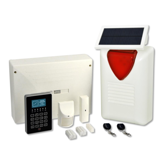
Page 5: What Includes The Wireless Kit Bs-468/A/Kit
Make sure the BS-479 extension is mounted on the panel. All the wireless peripheral devices (traps, radars, sirens, keyboards) do not have their batteries installed. We place the BS-468/A board in the position we have chosen for installation and connect it to the mains supply, according to the following diagram. -
Page 6: Installation Methods
1.4 Installation methods BS-468/A comes with factory predefined codes for: User (Master): 1-2-3-4 Installer-Technician: 9-9-9-9 A. PC To proceed with installation through a computer, please refer to the user manual Section 3.6 "Programming via computer". B. BS-466/A wired Keyboard The installation process through the wired keyboard is the same as that of the wireless keyboard in steps 3 and 5 (see installation mode C). -
Page 7: Detection Of Network's Devices
NOTE: If you have purchased the wireless kit, then the BS-477 wireless Keypad inside the kit is already synchronized with BS-468/A panel. You only need to install all the other devices from the BS-477 menu. If you have purchased the panel with the Keypad separately, then you must first synchronize the keyboard with the panel and then install the rest of the devices from the BS-477 keypad. -
Page 8: Detection Of Wireless Devices
device should have the battery connected as long as the above procedure is running. The keypad detection process has a 1-minute timeout period, since the LD4 starts flashing. If no keypad is inserted for 1 minute, LD4 will go out. To start the procedure again, the BT1 button must be pressed again. -
Page 9: Device's Installation
5. If 32 devices are already installed and a user tries to add another, 4 long beeps will be heard. No other devices can be installed. 6. By pressing "# " the installation procedure stops. NOTE: For every change in the wireless zone menu and during the extensions scan, an amount of time is needed in order to update the data of the wireless system. -
Page 10: Starting Up The Installed System
of the correct dip switches position. In infrared sensors the dip switches adjust the sensitivity and whether the zone is with or without delay. On magnetic sensors the switches adjust the zone delay and the internal sensor activation (in case the user wants to connect external). For delayed alarm selection, the dip switch 1 must be ON in the BS-470, while in the BS-471 the dip switch 2 must be in the ON position. -
Page 11: Installation Completion
If you have purchased a GSM or PSTN extension, refer to the corresponding paragraphs of the BS-468/A technical manual, as well as these devices' manuals, to install them on the system. The installation procedure has come to its end. -
Page 12: Device's Control Operation
INSTALLATION PROCEDURE: For the best possible ease and speed, have the devices in front of you. Put the BS-468/A panel in installation mode and place the batteries one at a time on the devices, followed by tamper press and release after each battery installation. -
Page 13: Entrance, Exit, Extra Time Settings
6.3 Entrance, exit, extra time settings The exit time must be sufficient enough for the user to leave the guarded area before the system arms. Entry time should be enough for the user to enter the password for system disarm. It is advisable not to be marginal, in case of accidentally mistyped passwords. -
Page 14: Handling The System With The Wireless Keypad
7. HANDLING THE SYSTEM WITH THE WIRELESS KEYPAD 7.1 Key Operations and Functions of the Wireless Keyboard Page 14 921468007_90_005... -
Page 15: Basic Menu
7.2 Basic Menu ______MEΝU______ Password Password BYPASS ZONES BYPASS W/LESS ZONES 9-9-9-9 1-2-3-4 MASTER OR TECH MENU WIRED ZONE CONDITION WLESS ZONE CONDITION LAST ALARMS* ALL EVENTS __TECHNICIAN MENU__ __MASTER MENU__ MANUAL OUTPUTS CHECK EVENTS EVENTS INFORMATION CODES CODES SETTINGS SETTINGS TIMERS TIMERS... -
Page 16: Wireless Keypad Activation
Depending on the mode of operation, the arm and disarm operations differ. Arm, disarm, silent alarm and panic alarm on BS-468/A can be activated through RF- 467 telecontrol, which is given (2 pieces) preinstalled. For more information regarding the installation and usage of these devices, please refer to last 3 pages of this guide. - Page 17 C section is armed. If the system was fully armed then the symbols Α, Β, C would have been displayed. When the system is disarmed, the lock is removed and the Olympia electronics logo is displayed once gain. Page 17...
-
Page 18: Advanced Operations
7.5 Advanced Operations By pressing the ( ) key, the screen shows: Using the up and down keys (keys 2 and 8), we can MENU move the cursor upwards or downwards. By using BYPASS ZONES the ( ) key the user can achieve the required BYPASS W/LESS ZONES MASTER OR TECH MENU selection. - Page 19 screen will display the previous message "ALL ZONES OK". With this method we can test the good operation of all the detectors and magnetic contacts. The same applies to "WLESS ZONE CONDITION", except the fact that the menu is dedicated to wireless zones. By pressing "LAST ALARMS", the user can examine the alarms that were triggered during the last arming of the system.
-
Page 20: Wireless Zones Events
However the "Tamper Alarm" event will exist on the keypad screen. 8. BS-468/A REMOTE CONTROL 8.1 General The wireless alarm kit you have purchased, has 2 remote controls pre-installed for remote operation of basic functions. -
Page 21: Installation
➢ DESCRIPTION • RF-467 (Photo 1) is a remote control transmitter with four keys. In BS-468/A it performs the following functions: A. System arming B. System disarming C. -
Page 22: Codes Deletion Procedure On Rf-467
For Android you can download the app visiting the site of Olympia Electronics. https://support.olympia-electronics.gr/olympia_pub/i-Olympia.apk For iOS download it from App Store using the key word “olympia electronics alarm”. Selecting the menu “app’s help” you will find the full manual of the product. -
Page 23: Alarm's Faults
10. COMMON FAULT INDICATIONS Fault Cause and Solution Problem with the panel's battery. Contact "PANEL, OVERCHARGE" your technician. Problem with the panel's battery. Contact "PANEL, UNDERCHARGE" your technician. Check the battery cable connections. If the "PANEL, DISCONNECTED BATTERY" problem persists, contact your technician. Check the power supply connections of the panel. -
Page 24: Warranty
Olympia Electronics reserves the right to repair or to replace the returned goods and to or not charge the buyer depending on the reason of defection. Olympia Electronics reserves the right to charge or not the buyer the transportation cost.
Need help?
Do you have a question about the BS-468/A and is the answer not in the manual?
Questions and answers