
Related Manuals for Zennio ALLinBOX 1612 v2


Summary of Contents for Zennio ALLinBOX 1612 v2
- Page 1 ➢ ALLinBOX 1612 v2 Multifunction device with power supply, KNX-IP Interface, 16 outputs, 12 inputs and logical module ZPR1612V2 Application program version: [1.4] User manual edition: [1.4]_a www.zennio.com...
-
Page 2: Table Of Contents
ALLinBOX 1612 v2 CONTENTS Contents ............................2 Introduction .......................... 3 1.1 ALLinBOX 1612 v2 ......................3 1.2 Installation ........................5 1.3 Start-Up and Power Loss ....................7 1.4 LED Indicators ........................8 1.5 Hard Reset to Factory Defaults ..................10 1.6 Hard Reset power supply .................... -
Page 3: Introduction
ALLinBOX 1612 v2 1 INTRODUCTION 1.1 ALLinBOX 1612 V2 ALLinBOX 1612 v2 is a versatile KNX actuator featuring a wide variety of functions: 16 relay outputs, configurable as: ➢ Up to 8 independent shutter channels (with or without slats), ➢ Up to 16 individual ON/OFF outputs, ➢... - Page 4 ALLinBOX 1612 v2 IP interface ➢ Up to 5 parallel connections from ETS for programming and monitoring. ➢ High capacity buffer 6 light indicators (LEDs): two state indicators for the power supply (power and overload), one power supply factory reset indicator, two state indicators for the lines (bus and Ethernet), one more IP factory reset indicator, and one additional indicator for the programming mode.
-
Page 5: Installation
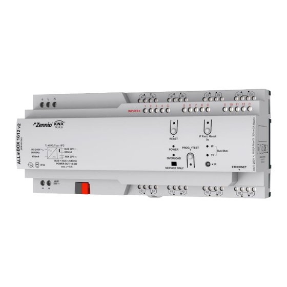
19. Remote Control (not included). Figure 1. ALLinBOX 1612 v2 elements scheme. Figure 1 shows a scheme of ALLinBOX 1612 v2 with all the LED indicator and required connections. ALLinBOX 1612 v2 has its own power supply, so it does not need an additional one and it serves to supply the rest of the devices through the KNX bus. - Page 6 To get detailed information about the technical features of this device, as well as on the installation and security procedures, please refer to the corresponding Datasheet, bundled with the original package of the device and also available at www.zennio.com. http://www.zennio.com Technical Support: http://support.zennio.com...
-
Page 7: Start-Up And Power Loss
Please consult the next sections of this document for further details. On the other hand, when a bus power failure takes place, ALLinBOX 1612 v2 will interrupt any pending actions, and will save its state so it can be recovered once the power supply is restored. -
Page 8: Led Indicators
ALLinBOX 1612 v2 1.4 LED INDICATORS ALLinBOX 1612 v2 incorporates 7 LED lights on the top of the device that make it easy to monitor the status of the buses and to detect typical communication problems, as detailed next. Figure 2. LEDs KNX Line Status LED (TP): shows the status of the primary bus. - Page 9 ALLinBOX 1612 v2 Overload LED (OVERLOAD): notifies a high consumption in the power supply. ➢ OFF: device with low power consumption. ➢ ON (red): device with too high consumption. ➢ BLINKING (green): short circuit in the power supply. Programming LED: ➢...
-
Page 10: Hard Reset To Factory Defaults
ALLinBOX 1612 v2 1.5 HARD RESET TO FACTORY DEFAULTS By pressing the "IP Factory Reset" button for three seconds: The device will adopt an IP address via the DCHP server. ➢ If the DHCP client does not obtain a valid IP address (after several... -
Page 11: Hard Reset Power Supply
ALLinBOX 1612 v2 1.6 HARD RESET POWER SUPPLY If “Reset” button is pressed, a short circuit is made in the output power supply (29V). The device will not restart (and will not have voltage) until the button is released. http://www.zennio.com Technical Support: http://support.zennio.com... -
Page 12: Configuration
2.1 KNX TO IP INTERFACE ALLinBOX 1612 v2 is an interface device intended for the interconnection between a KNX bus and an Ethernet network (LAN). The network parameters can be configured in the "IP" panel of the ETS "Properties":... -
Page 13: Programmer
2.2 PROGRAMMER ALLinBOX 1612 v2 can be used in ETS as a programming interface. In addition to an IP address, they must be assigned a KNX individual address for this purpose. Up to five simultaneous connections are allowed for performing downloads or for bus monitoring. -
Page 14: Parallel Downloads
This option is only available for connections via a KNX-IP router or a KNX-IP interface. Certain conditions must be met: Each download must be performed on a different line. For each line, it is necessary to select one ALLinBOX 1612 v2 to perform the download. http://www.zennio.com Technical Support: http://support.zennio.com... - Page 15 ALLinBOX 1612 v2 Note: There is a restriction: parallel downloads are not available to download physical addresses. When performing this type of downloads, the link device used by ETS is not the one configured for the line but the general one.
-
Page 16: Addicional Individual Addresses (Tunneling Addresses)
After the individual ALLinBOX 1612 v2 address has been set, the five tunneling addresses are automatically set with consecutive values. This can be changer at any time. -
Page 17: General
ALLinBOX 1612 v2 2.4 GENERAL After importing the corresponding database in ETS and adding the device into the topology of the desired project, the configuration process begins by entering the Parameters tab of the device. ETS PARAMETERISATION The "General" tab contains general settings. From this screen it is possible to activate/deactivate all the required functionality. - Page 18 ALLinBOX 1612 v2 Logic Functions [disabled/enabled]: enables o disables the “Logic Functions” tab on the left menu. See section 2.9 for more details. Scene Timing [disabled/enabled]: enables o disables the “Scene Timing” tab on the left menu. See section 2.10 for more details.
- Page 19 ALLinBOX 1612 v2 Show Relay Switches Counter Objects [disabled/enabled]: enables two communication objects to keep track of the number of switches performed by each of the relays ("[Relay X] Number of Switches") and the maximum number of switches carried out in a minute ("[Relay X] Maximum Switches per Minute").
-
Page 20: Inputs
Please refer to the “Temperature Probe” user manual, available under the ALLinBOX 1612 v2 product section at www.zennio.com. 2.5.3 MOTION DETECTOR It is possible to connect motion detectors from Zennio to the input ports of ALLinBOX 1612 v2. Please refer to the “Motion Detector” user manual, available under the ALLinBOX 1612 v2 product section at www.zennio.com, for detailed information about the... -
Page 21: Outputs
Each channel can be configured through the drop-down list as two independent binary outputs or as a shutter channel (which makes use of both relays). ALLinBOX 1612 v2 incorporates fan coil control modules, which will be responsible for operating the relays than open and close the water pipe valves (either one three- point valve or up to two on-off valves), and the relays that set the fan speed level. - Page 22 For detailed information about the functionality and the configuration of the related parameters, please refer to the following specific manuals, all of them available under the ALLinBOX 1612 v2 product section at the Zennio homepage (www.zennio.com): Individual outputs. Shutter channels.
-
Page 23: Thermostats
The use of the Hospitality thermostat is only recommended for hotel rooms. Please refer to the specific “Thermostat” or “Hospitality Thermostat” user manual available under the ALLinBOX 1612 v2 product section at the Zennio homepage (www.zennio.com) for detailed information about the functionality and the configuration of the related parameters. -
Page 24: Master Light
This function brings the option to monitor the state of 2 master light modules up to 12 light sources (or even more, if the Master Light controls from multiple Zennio devices are linked together) or of any other elements whose state is transmitted through a binary object and, depending on those states, perform a master order every time a certain trigger signal (again, a binary value) is received through a specific object. - Page 25 ALLinBOX 1612 v2 ETS PARAMETERISATION Once the Master Light function has been enabled, a specific tab will be included in the menu on the left. This new parameter screen (Figure 12) contains the following options: Figure 12. Master Light Number of State Objects [1…12]: defines the number of 1-bit status objects required.
- Page 26 ALLinBOX 1612 v2 ➢ Binary Value [disabled/enabled]: if checked, object “[ML] General Switch-off: Binary Object” will be enabled, which will send one “0” whenever the general switch-off takes off. ➢ Scaling [disabled/enabled]: if checked, object “[ML] General Switch-off: Scaling” will be enabled, which will send a percentage value (configurable in Value [0…100]) whenever the general switch-off takes off.
-
Page 27: Logic Functions
KNX bus, and to send the results through other communication objects specifically enabled for this purpose. ALLinBOX 1612 v2 can implement up to 20 different and independent functions, each of them entirely customisable and consisting in up to 4 consecutive operations each. -
Page 28: Scene Timing
ALLinBOX 1612 v2 2.10 SCENE TIMING The scene timing enables the imposition of delays over the scenes of the outputs. These delays, defined in parameters, are applied on the execution of one or more scenes that may have been configured. - Page 29 ALLinBOX 1612 v2 Figure 14. Configuring Scene Timing Therefore, parameter Scene n. Z Delay [0…3600][s] [0…1440][min] [0…24][h] defines the delay that will be applied to the action defined in Z (being Z a specific individual output, shutter channel or fan coil module) for the execution of scene m.
-
Page 30: Manual Control Through Ir Remote Control
ALLinBOX 1612 v2 2.11 MANUAL CONTROL THROUGH IR REMOTE CONTROL ALLinBOX 1612 v2 enables the manually switching the state of its output relays through the pushbuttons of an IR remote control. A specific pushbutton on the IR remote control is therefore available per output. - Page 31 ALLinBOX 1612 v2 Test On Mode After entering the Test On mode, it will only be possible to control the outputs through the IR remote control pushbuttons. Orders received through communication objects will be ignored, with independence of the channel or the output they are addressed to.
- Page 32 ALLinBOX 1612 v2 Disabled output: short and long presses will switch the state of the corresponding relay. In case this consists in closing the relay, then the remaining relays of its block will open, for safety reasons. As described previously if the device is in Test On mode, any command sent from the...
- Page 33 ALLinBOX 1612 v2 Manual Lock Control [disabled/enabled]: unless the above parameter has been “Disabled”, the Lock Manual Control parameter provides an optional procedure for locking the manual control in runtime. When this checkbox is enabled, object “Manual Control Lock” turns visible, as well as two more parameters: ➢...
-
Page 34: Annex I. Communication Objects
ALLinBOX 1612 v2 ANNEX I. COMMUNICATION OBJECTS “Functional range” shows the values that, with independence of any other values permitted by the bus according to the object size, may be of any use or have a particular meaning because of the specifications or restrictions from both the KNX standard or the application program itself. - Page 35 ALLinBOX 1612 v2 155, 166, 177 13, 24, 35, 46, 57, 68, 79, 90, 101, 112, 123, 134, 145, 1 Bit C R - T - DPT_State [Ox] Warning Time (Status) 0=Normal; 1=Warning 156, 167, 178 14, 25, 36, 47, 58, 69, 80,...
- Page 36 ALLinBOX 1612 v2 196, 225, 254, 283, 312, 1 Bit C - W - - DPT_UpDown [Cx] Auto: Move 0=Raise; 1=Lower 341, 370, 399 1 Bit C - W - - DPT_Step [Cx] Auto: Stop/Step 0=Stop/StepUp; 1=Stop/StepDown 197, 226, 255, 284, 313,...
- Page 37 ALLinBOX 1612 v2 1 Bit C R - T - DPT_Enable [FCx] Fan: Manual/Automatic (Status) 0 = Manual; 1 = Automatic 421, 454 1 Bit C - W - U DPT_Step [FCx] Manual Fan: Step Control 0 = Down; 1 = Up...
- Page 38 ALLinBOX 1612 v2 (1 bit) [FCx] Cooling Valve: Control Variable 1 Bit C - W - U DPT_Switch 0 = Close Valve; 1 = Open Valve (1 bit) [FCx] Heating Valve: Control Variable 1 Bit C - W - U DPT_OpenClose 0 = Open Valve;...
- Page 39 ALLinBOX 1612 v2 [Ix] [Short Press] Move Up/Down 1 Bit C - - T - DPT_UpDown Switching 0/1 (Up/Down) Shutter [Ix] [Short Press] Stop/Step Up 1 Bit C - - T - DPT_Step Sending of 0 (Stop/Step Up) Shutter [Ix] [Short Press] Stop/Step Down...
- Page 40 ALLinBOX 1612 v2 [Ix] [Short Press] Constant Value C - - T - DPT_Value_2_Ucount 0 - 65535 0 - 65535 Bytes (Integer) [Ix] [Short Press] Constant Value C - - T - 9.xxx -671088.64 - 670433.28 Float Value Bytes (Float)
- Page 41 ALLinBOX 1612 v2 0xD (Inc. by 100%) 0xF (Inc. by 1%) 1 Bit C - - T - DPT_Switch [Ix] [Long Press] Light On Sending of 1 (On) 1 Bit C - - T - DPT_Switch [Ix] [Long Press] Light Off...
- Page 42 ALLinBOX 1612 v2 881, 910 3=Economy 4=Building Protection 592, 621, 650, 679, 708, 1 Bit C R - T - DPT_Switch [Ix] Presence State (Binary) Binary Value 737, 766, 795, 824, 853, 1 Bit C R - T - DPT_Start...
- Page 43 ALLinBOX 1612 v2 839, 844, 863, 868, 873, 892, 897, 902, 921, 926, 603, 608, 613, 632, 637, 642, 661, 666, 671, 690, 695, 700, 719, 724, 729, 748, 753, 758, 777, 782, 1 Bit C R - T -...
- Page 44 ALLinBOX 1612 v2 1007, 1008, 1009, 1010, 1011, 1012, 1013, 1014, 1015, 1016, 1017, 1018, 1019, 1020, 1021, 1022, 1023, 1024, 1025, 1026, 1027, 1028, 1029, 1030, 1031, 1032, 1033, 1034, 1035, 1036, 1037, 1038, 1039, 1040, 1041, 1042, 1043, 1044, 1045, 1046...
- Page 45 ALLinBOX 1612 v2 1152, 1153, 1154, 1155, 1156, 1157, 1158, 1159, 1170, 1171, 1172, 1173, 1174, 1175, 1176, 1177, 1178, 1179, 1180, 1181 1160, 1182 1 Bit C R - T - DPT_Switch [MLx] General Status Binary Status [MLx] General Switch Off: Binary...
- Page 46 ALLinBOX 1612 v2 1 Bit C - W T U DPT_Switch [HTx] [A] Fan: Manual/Automatic 0 = Automatic; 1 = Manual 1203, 1271, 1339, 1407 1 Bit C R - T - DPT_Switch [HTx] [A] On/Off Fancoil 0 = Off; 1 = On...
- Page 47 ALLinBOX 1612 v2 [HTx] [C] Transition Time: Standby to C R W T U DPT_TimePeriodMin 0 - 65535 Minutes (0 = Disabled) Bytes Economy [HTx] [C] Transition Time: Standby to C R W T U DPT_TimePeriodHrs 0 - 65535 Hours (0 = Disabled)
- Page 48 ALLinBOX 1612 v2 1 Bit C - W - - DPT_Window_Door [HTx] [D] Window Status 4 (Input) 0 = Closed; 1 = Open 1233, 1301, 1369, 1437 1 Bit C - W - - DPT_Window_Door [HTx] [D] Window Status 4 (Input) 0 = Open;...
- Page 49 ALLinBOX 1612 v2 1256, 1324, 1392, 1460 1 Bit C R - T - DPT_Switch [HTx] [Heating] Additional Heat Temp <= (Setpoint-Band) => "1" 0 = PI Signal 0%; 1 = PI Signal 1257, 1325, 1393, 1461 1 Bit C R - T -...
- Page 50 ALLinBOX 1612 v2 1478, 1516, 1554, 1592 C R - T - DPT_Value_Temp -273.00º - 670433.28º [Tx] Setpoint Status Current Setpoint Bytes 1479, 1517, 1555, 1593 C R - T - DPT_Value_Temp -273.00º - 670433.28º [Tx] Basic Setpoint Status Current Basic Setpoint...
- Page 51 Join and send us your inquiries about Zennio devices: http://support.zennio.com Zennio Avance y Tecnología S.L. C/ Río Jarama, 132. Nave P-8.11 45007 Toledo, Spain. Tel. +34 925 232 002. www.zennio.com info@zennio.com...
Need help?
Do you have a question about the ALLinBOX 1612 v2 and is the answer not in the manual?
Questions and answers