
Related Manuals for Bresser DeepSky Astro


Summary of Contents for Bresser DeepSky Astro
- Page 1 Digital camera · Digitalkamera · DeepSky Astro-Kamera 26MP Instruction manual Bedienungsanleitung...
- Page 2 Desidera ricevere informazioni esaustive su questo prodotto in una lingua specifica? Venga a visitare il nostro sito Web al seguente link (codice QR Code) per conoscere le versioni disponibili. www.bresser.de/P0510540 GARANTIE · WARRANTY · GARANTÍA · GARANZIA www.bresser.de/warranty_terms RECYCLAGE (TRIMAN/FRANCE)
- Page 3 English ........................Deutsch ........................
-
Page 4: Table Of Contents
Contents 1 Imprint ................................ 5 2 Validity note .............................. 5 3 About this Instruction Manual........................ 5 4 Intended use .............................. 5 5 General safety instructions ........................... 6 6 Parts overview and scope of delivery ...................... 8 7 Installing the software and drivers ....................... 9 8 Camera mounting on telescope........................ -
Page 5: Imprint
We ask for your understanding that unsolicited returns cannot be pro- cessed. Errors and technical changes excepted. © 2022 Bresser GmbH All rights reserved. The reproduction of this documentation - even in extracts - in any form (e.g. photocopy, print, etc.) as well as the use and distribution by means of electronic systems (e.g. -
Page 6: General Safety Instructions
5 General safety instructions DANGER Risk of an electric shock! This device contains electronic parts that are powered by a power source (AC adapter and/or batter- ies). Improper use of this product may result in electric shock. Electric shock can cause serious or fatal injuries. - Page 7 NOTICE Risk of overheating! Always keep the ventilation slits of the thermoelectric cooling system free! Covering these slits will re- duce cooling performance and may cause overheating and damage to the camera. NOTICE Risk of material damage due to solar radiation! Do not expose the camera sensor to direct sunlight.
-
Page 8: Parts Overview And Scope Of Delivery
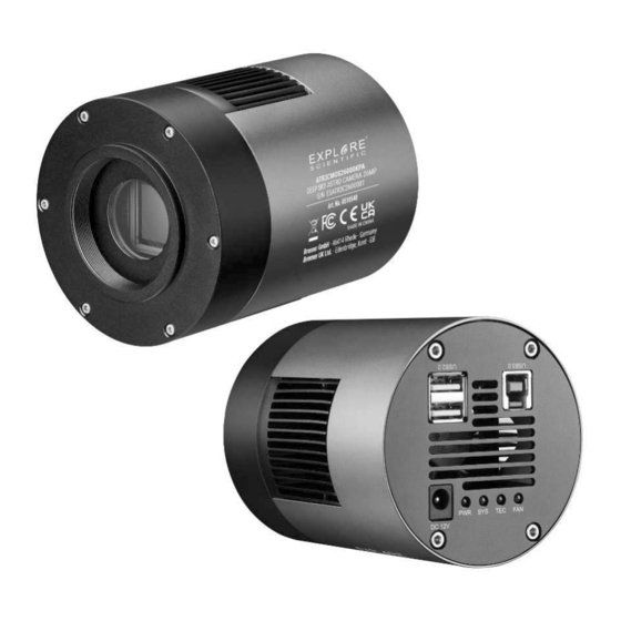
6 Parts overview and scope of delivery Illustration 1: All parts of the Astro camera with rear view (connection area) 1 Camera housing 2 Ventilation slits 3 Holding thread 4 USB 2.0 socket (2x USB HUB) 5 USB 3.0 socket (1x) 6 Connection socket for DC barrel con- nector 7 PWR function light (power supply of the... -
Page 9: Installing The Software And Drivers
Scope of delivery: Camera (A); ); T2 adapter (B); power adapter (C); power cable (D); power cable extension (E); USB 3.0 connection cable (F); software CD; hardcase Also required (not included): Computer running Windows 8/10 NOTICE! This is not a stand-alone camera. A computer with Windows operating system and free USB 3.0 interface is required for operation. -
Page 10: Using The Internal Usb Hub (Usb 2.0)
1 Camera housing 2 Holding thread 3 Connection thread 4 50.8mm (2") T2 adapter 5 50.8mm (2") eyepiece holder 6 Eyepiece extension 9 Using the internal USB HUB (USB 2.0) The camera is equipped with an built-in USB HUB with 2x USB 2.0 sockets at the rear. This can be used to connect additional components (e.g. -
Page 11: Cleaning And Maintenance
13 EC declaration of conformity A "Declaration of conformity" in accordance with the applicable directives and correspond- ing standards has been prepared by Bresser GmbH. The full text of the EC declaration of conformity is available at the following Internet address: www.bresser.de/down- load/0510540/CE/0510540_CE.pdf... -
Page 12: Technical Data
16 Technical data Art.No.: 0510540 Camera type/model: ASTRO camera 26.0MP/ATR3CMOS26000KPA Data output: Images and videos Image sensor: Sony IMX571 CMOS color sensor Adjustable resolution 5224x4168 / 3104x2084 /1064x1386 in pixels: Adjustable binning: 1x1 / 2x2 / 3x3 Frame rate per second (FPS): 110 / 37.1 / 14.2 / 6.8 Physical sensor size in pixels: 6224 x 4168... - Page 13 1750 mm 46' x 31' (0.8 x 0.5 degrees) 2000 mm 40' x 27' (0.7 x 0.4 degrees) 13 / 28...
- Page 14 Inhaltsverzeichnis 1 Impressum .............................. 15 2 Gültigkeitshinweis............................ 15 3 Zu dieser Anleitung............................ 15 4 Verwendungszweck ............................. 15 5 Allgemeine Sicherheitshinweise......................... 16 6 Teileübersicht und Lieferumfang........................ 18 7 Software und Treiber installieren ....................... 19 8 Kamera-Montage am Fernrohr ........................ 20 9 Nutzung des internen USB-HUB (USB 2.0) .................... 20 10 Kamera-Montage mit optionalem Autoguider ...................
-
Page 15: Impressum
„Garantie“ und „Service“ in dieser Dokumentation. Wir bitten um Verständnis, dass unaufgeforderte Rücksendungen nicht bearbeitet werden können. Irrtümer und technische Änderungen vorbehalten. © 2022 Bresser GmbH Alle Rechte vorbehalten. Die Reproduktion dieser Dokumentation – auch auszugsweise – in irgendeiner Form (z.B. Fotokopie, Druck, etc.) sowie die Verwendung und Verbreitung mittels elektronischer Systeme (z.B. -
Page 16: Allgemeine Sicherheitshinweise
• Es wurde entwickelt als elektronisches Zubehörteil zum ausschließlichen Anschluss und Betrieb an in dieser Anleitung beschriebenen privat genutzten Geräten. 5 Allgemeine Sicherheitshinweise GEFAHR Gefahr eines Stromschlags! Dieses Gerät beinhaltet Elektronikteile, die über eine Stromquelle (Netzteil und/oder Batterien) betrie- ben werden. Bei unsachgemäßer Verwendung dieses Produkts besteht die Gefahr eines Strom- schlags. - Page 17 HINWEIS Gefahr eines Spannungschadens! Benutzen Sie zur Spannungsversorgung ausschließlich das im Lieferumfang enthaltene Netzteil! Die Verwendung anderer nicht geeigneter oder vom Hersteller nicht autorisierter Spannungsquellen kann zu einer Beschädigung der Kamera und zum Verlust der Garantie führen. HINWEIS Überhitzungsgefahr! Die Lüftungsöffnungen der thermoelektrischen Kühlungssystems stets freihalten! Eine Abdeckung die- ser Öffnungen führt zu einer verminderten Kühlleistung und kann zu einer Überhitzung und Beschädi- gung der Kamera führen.
-
Page 18: Teileübersicht Und Lieferumfang
6 Teileübersicht und Lieferumfang Abb. 1: Alle Teile der Astro-Kamera mit Rückansicht (Anschlussbereich) 1 Kamera-Gehäuse 2 Lüftungsschlitze 3 Aufnahmegewinde 4 USB 2.0-Anschluss (2x USB-HUB) 5 USB 3.0-Anschluss (1x) 6 Anschlussbuchse für DC-Hohlstecker 7 PWR-Funktionsleuchte (Spannungsver- 8 SYS-Funktionsleuchte (USB-Verbindung sorgung der Kamera hergestellt) hergestellt) 9 TEC-Funktionsleuchte (Kühlung aktiv) 10 FAN-Funktionsleuchte (Lüfter aktiv) -
Page 19: Software Und Treiber Installieren
Kamera (A); ); T2-Adapter (B); Netzadapter (C); Spannungskabel (D); Spannungskabel-Verlängerung (E); USB 3.0-Verbindungskabel (F) Software-CD; Hardcase Außerdem erforderlich (nicht im Lieferumfang enthalten): Computer mit Windows 8/10 HINWEIS! Dies ist keine Stand-alone-Kamera. Für den Betrieb ist ein Computer mit Windows- Betriebssystem und freier USB 3.0 Schnittstelle erforderlich. 7 Software und Treiber installieren 1. -
Page 20: Kamera-Montage Am Fernrohr
8 Kamera-Montage am Fernrohr Abb. 3: Montage der Kamera am Fernrohr 1 Kamera-Gehäuse 2 Aufnahmegewinde 3 Anschlussgewinde 4 50,8mm (2“) T2-Adapter 5 50,8mm (2“) Okularaufnahme 6 Okularauszug 9 Nutzung des internen USB-HUB (USB 2.0) Die Kamera besitzt an der Rückseite einen eingebauten USB-HUB mit 2x USB 2.0-Anschlüssen. Hier- über können eine zusätzliche Komponenten (z.B. -
Page 21: Kamera-Montage Mit Optionalem Autoguider
10 Kamera-Montage mit optionalem Autoguider Abb. 4: Montage der Deep Sky Astro-Kamera mit optionaler Autoguider-Kamera 1 Autoguider-Kamera 2 ST4-Verbindungskabel 3 USB 3.0-Verbindungskabel 4 Leitrohr 5 Fernrohr 6 ST4-fähige Montierung 7 Control Panel der Montierung 8 ST4-Port am Control Panel 9 Deep Sky Astro-Kamera 10 Computer 11 USB 3.0-Port an der Kamera 12 USB 2.0-Port an der Kamera... -
Page 22: Reinigung Und Wartung
Wiederverwertung zugeführt werden. 13 EG-Konformitätserklärung Eine „Konformitätserklärung“ in Übereinstimmung mit den anwendbaren Richtlinien und entsprechenden Normen ist von der Bresser GmbH erstellt worden. Der vollständige Text der EG-Konformitätserklärung ist unter der folgenden Internetadresse verfügbar: www.bresser.de/download/0510540/CE/0510540_CE.pdf 14 Garantie Die reguläre Garantiezeit beträgt 2 Jahre und beginnt am Tag des Kaufs. - Page 23 Auflagemaß: 17,5 mm Verschlussart: Global Shutter Interner Kamera-Speicher: DDR 3 RAM Thermoelektrische Kühlung mit Lüfter: ja, bis 40°C unter Umgebung Einstellbare Belichtungszeiten: 150 µs bis 60 min Betriebstemperatur: -10 bis +50°C (30-80% rH) Kabellänge USB 3.0: 150 cm Kabellänge DC-Netzteil: 200cm Gehäuse: CNC-gefertigtes Gehäuse aus Aluminium...
- Page 27 (de preferencia por e-mail). E-Mail: service@bresseruk.com E-Mail: servicio.iberia@bresser-iberia.es Telephone*: +44 1342 837 098 Teléfono*: +34 91 67972 69 BRESSER UK Ltd. BRESSER Iberia SLU Suite 3G, Eden House c/Valdemorillo,1 Nave B Enterprise Way P.I. Ventorro del Cano Edenbridge, Kent TN8 6HF 28925 Alcorcón Madrid...
- Page 28 Bresser GmbH Gutenbergstraße 2 46414 Rhede · Germany www.explorescientific.de...
Need help?
Do you have a question about the DeepSky Astro and is the answer not in the manual?
Questions and answers