Chapters
Table of Contents
Troubleshooting

Related Manuals for Hyster D435 Series


Summary of Contents for Hyster D435 Series
- Page 1 Part no.: 4065749 Revision: 1 (12/2014) Technical information for Hyster service centres This manual is intended solely for the specialized technicians of the Hyster service network. R1.4 R1.6N R1.6 R1.6HD D435..R2.0 R2.0HD R2.5...
- Page 2 The Service Manuals are updated regularly, but may not contain the most recent product design modifica- tions. The updated technical information is in any case available from your nearest authorised Hyster® dealer. The Service Manuals provide the guidelines for correct maintenance and are designed for use by appropriately trained technicians.
- Page 3 SERVICE INTRODUCTION GUIDE TO USING THE MANUAL SECTIONS This handbook is composed of the following sections: Section 1: Presentation Section 2: Installation and settings Section 3: Diagnostics and measurements Section 4: Electrical system Section 5: Hydraulic system Section 6: Truck base mechanics Section 7: Mast assembly mechanics Section 8:...
- Page 4 SERVICE INTRODUCTION GENERAL SAFETY RULES PERSONAL SAFETY • Always wear the personal protective equipment in situations requiring it. • Pay particular attention to the risk of getting crushed due to moving parts, oscillations, material not properly secured when performing lifting operations or moving loads. •...
- Page 5 SERVICE INTRODUCTION • Before using the batteries, make sure that both ends of the cables are connected to the terminals as prescribed: (+) with (+) and (-) with (-). • Do not short-circuit the terminals. • The gas released when charging is highly flammable. When charging, leave the battery compartment uncovered for more effective ventilation and take off the plugs.
- Page 6 SERVICE INTRODUCTION Belt capacity table Colour purple 1000 2000 1400 green 2000 4000 2800 1600 yellow 3000 6000 4200 2400 grey 4000 8000 5600 3200 5000 10000 7000 4000 brown 6000 12000 8400 4800 Working load blue 8000 16000 11200 6400 capacity (kg) orange...
- Page 7 SERVICE INTRODUCTION Suspension element capacity table Colour purple 1000 1400 2100 2100 green 2000 2800 4200 4200 Working load yellow 3000 3800 6300 6300 capacity (kg) grey 4000 5600 8400 8400 5000 6600 9800 10500 Coefficient Working load capacity: the working load capacity is calculated with an angle at the centre of 90°...
- Page 8 SERVICE INTRODUCTION TORQUE SETTINGS FOR SCREWS, NUTS AND FITTINGS Before disassembling the various parts TORQUE SETTING Nm Nominal and nuts and bolts, read the following diameter carefully. Class 8 Class 10 To make the threaded matings secure, LOCTITE 270 is used for tightening the screws.
- Page 9 SERVICE INTRODUCTION CORRECT METHOD FOR APPLYING FEMALE FITTINGS To assure a reliable seal between female fittings and the adapters in this manual, it is necessary to observe the following procedure, which differs from the one for assembling rigid pipes. Female fittings without a gasket (metal/metal joint) Screw on the nut by hand and then, with the aid of a wrench, tighten by another quarter turn.
- Page 10 SERVICE INTRODUCTION INSTRUCTIONS FOR INSTALLING FLEXIBLE HOSES AND FITTINGS Inspection of pipes and fittings When even just one of the following conditions arises the pipe must immediately be disconnected and replaced: • a shift of the connector on the pipe; •...
- Page 11 SERVICE INTRODUCTION SECTION CONTENTS Presentation Installation and settings Diagnostics and measurements Electrical system Hydraulic system Truck base mechanics Mast assembly mechanics Small fork mast mechanics Reduction gear Braking system Standard maintenance...
- Page 12 SERVICE INTRODUCTION...
-
Page 13: Table Of Contents
SERVICE PRESENTATION Presentation trUCK Presentation ������������������������������������������������������������������������������������������������������������������������������������������� 2 VIEWS OF THE TRUCK ��������������������������������������������������������������������������������������������������������������������������������������������� 3 trUCK anD LoaD iDentiFiCation Data ����������������������������������������������������������������������������������������������������������� 4 TRUCK IDENTIFICATION DATA PLATE ��������������������������������������������������������������������������������������������������������������������� 4 RESIDUAL LOAD PLATE ������������������������������������������������������������������������������������������������������������������������������������������� 4 MAST SERIAL NUMBER PUNCHING AND LOCATION OF DOCUMENTATION ������������������������������������������������������ 5 GeneraL sPeCiFiCations ������������������������������������������������������������������������������������������������������������������������������������... -
Page 14: Truck Presentation
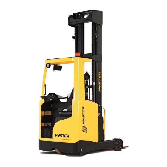
SERVICE PRESENTATION trUCK Presentation The new range of retractable trucks consists of 7 models with nominal load capacities from 1400 kg to 2500 kg� electrical system All the motors benefit from the use of three phase AC alternate current technology: traction motor, steering motor and pump motor�... -
Page 15: Views Of The Truck
SERVICE PRESENTATION VieWs oF tHe trUCK... -
Page 16: Truck And Load Identification Data
SERVICE PRESENTATION trUCK anD LoaD iDentiFiCation Data trUCK iDentiFiCation Data PLate The truck identification data plate is located inside the driver's cab • • Manufacturer's name Max. battery weight • • Model Min. battery weight • • Serial number Battery voltage •... -
Page 17: Mast Serial Number Punching And Location Of Documentation
SERVICE PRESENTATION Mast seriaL nUMBer PUnCHinG anD LoCation oF DoCUMentation xxxxxxxx The mast serial number is stamped on the The truck documentation is stored in the docu- mast itself� ment holder behind the backrest of the seat�... -
Page 18: General Specifications
SERVICE PRESENTATION GeneraL sPeCiFiCations... - Page 19 SERVICE PRESENTATION GeneraL sPeCiFiCations 1�2 manufacturer’s type designation r1�4 r1�6 r1�6n 1�3 motor unit: battery, diesel, LPG, petrol, electric electric (battery) 1�4 driving: manual, on ground, standing, seated seated 1�5 load capacity/rated load Q (t) 1�4 1�6 1�6 1�6 load centre of gravity c (mm) 1�8 load distance from load wheel axle - forks...
- Page 20 SERVICE PRESENTATION GeneraL sPeCiFiCations 1�2 manufacturer’s type designation r2�0 r2�5 1�3 motor unit: battery, diesel, LPG, petrol, electric electric (battery) 1�4 driving: manual, on ground, standing, seated seated 1�5 load capacity/rated load Q (t) 2�0 2�5 1�6 load centre of gravity c (mm) 1�8 load distance from load wheel axle - forks...
- Page 21 SERVICE PRESENTATION GeneraL sPeCiFiCations 1�2 manufacturer’s type designation r1�6HD r2�0HD 1�3 motor unit: battery, diesel, LPG, petrol, electric electric (battery) 1�4 driving: manual, on ground, standing, seated seated 1�6 2�0 1�5 load capacity/rated load Q (t) 1�6 load centre of gravity c (mm) 1�8 load distance from load wheel axle - forks...
-
Page 22: Batteries Table
SERVICE PRESENTATION notes with load grille h4 + 508 mm (all models except for 2 ton and 2.5 ton), h4 + 443 mm (2 ton and 2.5 ton models only) with flashing light h6 + 120 mm; with protective grille h6 + 20 mm; with protective screen h6 + 30 mm with load wheel side cover: 1289 mm (all models except for Narrow, 2.5 ton, HD 2.0 ton versions), 1153 mm (Narrow model only), 1373 mm (2.5 ton, HD 2.0 ton models only) This value can vary by ±... - Page 23 SERVICE PRESENTATION 1�2 manufacturer’s type designation r1�6n 1�8 load distance from load wheel axle - forks x (mm) 1�9 wheelbase (WB) y (mm) 1450 1450 1450 1450 1450 2�1 weight with no load (including battery) 3111 3309 3115 3317 3514 2�3 load on axle with no load (front/rear) 1922/1189...
- Page 24 SERVICE PRESENTATION 1�2 manufacturer’s type designation r1�6HD 1�8 load distance from load wheel axle - forks x (mm) 1�9 wheelbase (WB) y (mm) 1450 1450 1450 2�1 weight with no load (including battery) 4038 4049 4270 2�3 load on axle with no load (front/rear) 2417/1621 2424/1625 2457/1813 2�4 load on axle with forks out with load (front/rear)
- Page 25 SERVICE INSTALLATION AND SETTINGS InstallatIon and settIngs BeFoRe InstallatIon ������������������������������������������������������������������������������������������������������������������������������������������� 2 WEIGHT TABLES �������������������������������������������������������������������������������������������������������������������������������������������������������� 2 tRUCK asseMBlY ��������������������������������������������������������������������������������������������������������������������������������������������������� 6 LIST OF MATERIALS RECEIVED FROM THE DEALER ������������������������������������������������������������������������������������������� 6 UNLOADING OFF THE TRUCK AND FITTING THE MAST TO THE TRUCK BASE ������������������������������������������������� 8 TOPPING UP THE OIL RESERVOIR������������������������������������������������������������������������������������������������������������������������...
- Page 26 SERVICE INSTALLATION AND SETTINGS BeFoRe InstallatIon Depending on the size of the mast and the kind of transportation (container, truck, etc�), the carriage may be shipped: • complete in vertical position (option A) • with the mast assembly separate from the truck base (option B)� In the second instance one must check in advance that one is equipped with all the tools necessary to bring it to the vertical position and fit the column (hire forklift truck, bridge crane, belts, etc.). These machines are tested for all their functions and the mast assemblies are then dismantled, tying the fork carrier plate to...
- Page 27 SERVICE INSTALLATION AND SETTINGS BATTERIES Weight (kg) type min� max� DIN C 48/420 DIN B DIN C 1016 48/560 DIN B 1018 DIN C 1099 1211 48/700 DIN B 1104 1216 48/840 DIN C 1282 1413 FORK CARRIAGE Weight Models (kg) R1�4 R1�6 R1�6N R2�0 115�6...
- Page 28 SERVICE INSTALLATION AND SETTINGS MAST ASSEMBLIES height, mast extended total auxiliary lift Free lift lowered dimensions Weight (mm) (mm) Model (mm) (mm) (kg) 5000 1648 2195 5563 5250 1734 2281 5813 5500 1820 2367 6063 5750 1906 2453 6313 6000 1992 2539 6563...
- Page 29 SERVICE INSTALLATION AND SETTINGS height, mast extended total auxiliary lift Free lift lowered dimensions Weight (mm) (mm) Model (mm) (mm) (kg) 7900 2614 3227 8513 1372 8150 2700 3313 8763 1401 8400 2786 3399 9013 1435 8650 2872 3485 9263 1464 8900 2958...
- Page 30 SERVICE INSTALLATION AND SETTINGS tRUCK asseMBlY lIst oF MateRIals ReCeIVed FRoM the dealeR CARRIAGE SOLD WITHOUT BATTERY The materials received from the dealer may vary according to whether or not optional accessories are included� Ref� description Truck base and mast assembled (option A) Truck base and mast separate (option B) Contrast rollers (optional) Battery runner rollers...
- Page 31 SERVICE INSTALLATION AND SETTINGS CARRIAGE SOLD WITH BATTERY The materials received from the dealer may vary according to whether or not optional accessories are included� Ref� description Truck base and mast assembled (option A) Truck base and mast separate (option B) Contrast rollers (optional) Battery runner rollers Forks...
- Page 32 SERVICE INSTALLATION AND SETTINGS UnloadIng oFF the tRUCK and FIttIng the Mast to the tRUCK Base equipment and tools fork lift truck open ended span- crane truck or lifting sling load capacity bridge crane torque wrench load capacity ladder 2500 kg load capacity 19 mm 2500 kg...
- Page 33 SERVICE INSTALLATION AND SETTINGS Phase 3 Fig� 2 OPEN ENDED SPANNER 19 mm Using the open ended spanner, unscrew and remove the screws securing both side blocks of the mast assembly (ref.A fig.2)� Remove the blocks (ref.B fig.2)� Using the bridge crane, slowly lift the mast assembly and rest it vertically on the truck base in the special housings (ref.C fig.2)�...
- Page 34 SERVICE INSTALLATION AND SETTINGS toPPIng UP the oIl ReseRVoIR Fig� 1 Before topping up the oil in the hydraulic oil reservoir make sure that the forks are fully lowered� equipment and tools T handle hex key funnel oil resistant gloves 5 mm Procedure Before starting work, ensure that you are wearing suitable...
- Page 35 SERVICE INSTALLATION AND SETTINGS InstallatIon oF the BatteRY WITH VERTICAL REMOVAL equipment and tools Fig� 1 bridge crane open ended load capacity spreader bar spanner 2000 kg 10 mm Procedure Before starting work, ensure that you are wearing suitable protective clothing� Move the truck to a safe place, away from the transit areas of other vehicles and pedestrians�...
- Page 36 SERVICE INSTALLATION AND SETTINGS WITH LATERAL REMOVAL equipment and tools bridge crane load capacity spreader bar rollerway Fig� 1 2000 kg Fig� 2 Procedure Before starting work, ensure that you are wearing suitable protective clothing� Move the truck to a safe place, away from the transit areas of other vehicles and pedestrians�...
- Page 37 SERVICE INSTALLATION AND SETTINGS CONNECTION OF CABLES TO BATTERY The positive battery terminal is identified with the redmarking or the symbol , while the negative pole is identified with bluemarking or the symbol � The battery connector cables are in turn marked with a red tag for the connection to the positive pole and a blue tag for the connection to the negative pole�...
- Page 38 SERVICE INSTALLATION AND SETTINGS asseMBlY oF MoVIng FoRKs Procedure Before starting work, ensure that you are wearing suitable protective clothing� Move the truck to a safe place, away from the transit areas of other vehicles and pedestrians� Phase 1 Using the controls in the cab, lift the fork carriage to facilitate fork as- sembly operations�...
- Page 39 SERVICE INSTALLATION AND SETTINGS ContRastIng RolleR asseMBlY equipment and tools open ended span- 19 mm Procedure Before starting work, ensure that you are wearing suitable Fig� 1 protective clothing� Move the carriage to a safe place, away from areas of transit of other vehicles and all pedestrians�...
- Page 40 SERVICE INSTALLATION AND SETTINGS lIst oF the settIngs and adJUstMents to Be CaRRIed oUt After assembling all the machine's components as described in the previous pages, the following operations must be carried out in the sequence given: • setting the battery voltage • Checking the conditions of use of the truck •...
- Page 41 SERVICE INSTALLATION AND SETTINGS Fig� 1 Fig� 3 Fig� 2 Fig� 4...
- Page 42 SERVICE INSTALLATION AND SETTINGS CheCK the CondItIons oF Use oF the tRUCK In order to ensure the safety personnel and materials, before proceeding with the opera- tions described below, it is important to assess the following: • the type of load to be moved •...
- Page 43 SERVICE INSTALLATION AND SETTINGS enaBlIng and PRogRaMMIng oF the leVel PRe-seleCtoR� To enable and program the height pre-selector see "LEVEL PRE-SELECTOR" section "ELECTRICAL SYSTEM"� enaBlIng and PRogRaMMIng MIddle FoRK lIFtIng BloCKs To enable and program the middle cab lifting blocks see "FORK LIFTING/LOWERING BLOCKS" section "ELECTRICAL SYSTEM"�...
- Page 44 SERVICE INSTALLATION AND SETTINGS...
- Page 45 SERVICE DIAGNOSTICS AND MEASUREMENTS Diagnostics anD measurements DescriPtion moDuLe connectors ����������������������������������������������������������������������������������������������������������������� 2 ace2 traction moDuLe ��������������������������������������������������������������������������������������������������������������������������������������� 2 ACE2 PUMP MODULE ����������������������������������������������������������������������������������������������������������������������������������������������� 3 EPs ACw MODULE ���������������������������������������������������������������������������������������������������������������������������������������������������� 4 MAsTER CONTROL CARD PREMIUM MODULE ����������������������������������������������������������������������������������������������������� 5 tester menu ����������������������������������������������������������������������������������������������������������������������������������������������������������� 7 ACE2 TRACTION MODULE ��������������������������������������������������������������������������������������������������������������������������������������� 7 ACE2 PUMP MODULE �����������������������������������������������������������������������������������������������������������������������������������������������...
-
Page 46: Description Module Connectors
SERVICE DIAGNOSTICS AND MEASUREMENTS DescriPtion moDuLe connectors ace2 traction moDuLe + 48V logic power supply + 5V auxiliary power supply for Hall effect sensors Input of accelerator sensor output 1 Drive selector (analogue forward/reverse) (digital forward) Reverse drive selector Input of service brake sensor output 2 Input CH A motor encoder + 12V power supply for motor encoder Horn negative... -
Page 47: Ace2 Pump Module
SERVICE DIAGNOSTICS AND MEASUREMENTS ace2 PumP moDuLe + 48V logic power supply + 5V auxiliary power supply for Hall effect sensors Not used Not used Not used Not used Input CH A motor encoder + 12V power supply for motor encoder Flasher negative Not used CAN communication line 2... -
Page 48: Eps Acw Module
SERVICE DIAGNOSTICS AND MEASUREMENTS ePs acW moDuLe CAN communication line 2 CAN communication line 2 Power supply positive Power supply positive Power supply positive Power supply negative Power supply negative Power supply negative Fan positive (+48V) Fan negative sensor with driving wheel at 90° sensor with driving wheel at 0°... -
Page 49: Master Control Card Premium Module
SERVICE DIAGNOSTICS AND MEASUREMENTS master controL carD Premium moDuLe + 48V output power supply Negative of proportional valve for carriage forward (PwM) Current controlled Negative of proportional valve for carriage backward (PwM) Current controlled Negative of diverter valve for Tilt or side shift (PwM) Current controlled Negative of diverter valve for 5th way (PwM) Current controlled Negative of electromagnet for battery block release (PwM) Current controlled Negative of reverse drive buzzer (PwM) Current controlled... - Page 50 SERVICE DIAGNOSTICS AND MEASUREMENTS + 48V logic power supply - Batt logic power supply CAN communication line 2 CAN communication line 2 Not used + 12V auxiliary power supply + 5V auxiliary power supply Not used side shift position sensor Not used Tilt position inclinometer input Encoder reset sensor input...
-
Page 51: Tester Menu
SERVICE DIAGNOSTICS AND MEASUREMENTS tester menu The main input and output signals can be measured in real time using the TEsTER function of the pro- grammer� The programmer acts as a multimeter capable of reading voltage, current and temperature� Certain of these menu parameters refer to functions whose status is received via Can bus, others refer to functions directly connected to the analog/digital inputs of the module�... -
Page 52: Vcm Module
SERVICE DIAGNOSTICS AND MEASUREMENTS Vcm moDuLe MAIN TEsTER MENU Parameter measurement unit WorKing Hours Hours Indicates the truck's working hours according to the setting of the HOUR COUNTER option ForK HeigHt Indicates the fork height off the ground in real time if the HEIGHT INDICATOR option is activated BatterY VoLtage Value of the voltage to 1 decimal place�... - Page 53 SERVICE DIAGNOSTICS AND MEASUREMENTS Parameter measurement unit PaLLet sWitcH ON/OFF� Level of the Pallet button seatBeLt sWitcH ON/OFF� Level of the seat belt button seat sWitcH ON/OFF� Level of the seat button BatterY out sW1 ON/OFF� Level of the Battery 1 disconnected sensor BatterY out sW2 ON/OFF�...
- Page 54 SERVICE DIAGNOSTICS AND MEASUREMENTS Parameter measurement unit neV1 outPut Value %� Percentage of battery voltage applied on EV1 (not used) reset encoDer #1 ON/OFF� Encoder reset sensor level encoDer #1 pulses Number of pulses ready by encoder 1 encoDer #2 pulses Number of pulses ready by encoder 2 rPm PumP...
- Page 55 SERVICE DIAGNOSTICS AND MEASUREMENTS Parameter measurement unit anaLog inPut #1 Value in volts� Level of the analog input A23 (truck potentiometer position) anaLog inPut #2 Value in volts� Level of the analog input A35 (not used) anaLog inPut #3 Value in volts� Level of the analog input B1 (side shift position) anaLog inPut #4 Value in volts�...
-
Page 56: Breakdown Search
SERVICE DIAGNOSTICS AND MEASUREMENTS BreaKDoWn searcH Warning memoriZation Enter the main menu 1 /alarms on the display to visualize the last 20 warnings memorized and the infor- mation relative to the total number of hours worked by the module, the number of times the warning has been activated and the number that identifies the module. -
Page 57: Ace2 Pump And Traction Module Diagnosis System
SERVICE DIAGNOSTICS AND MEASUREMENTS ace2 PumP anD traction moDuLe Diagnosis sYstem ace2 PumP anD traction moDuLe aLarms programmer message description effect state of the truck message sicos MC open, EB activated, • start up CALL The watchdog signal is traction/pump station- •... - Page 58 SERVICE DIAGNOSTICS AND MEASUREMENTS programmer message description effect state of the truck message sicos • switch-on (im- The MC coil has been ac- MC open, EB activated, mediately after the CALL tivated, but the MC fails to traction/pump station- MC closes) sERVICE contactor close�...
- Page 59 SERVICE DIAGNOSTICS AND MEASUREMENTS programmer message description effect state of the truck message sicos MC open (the control CALL The MC coil driver is dam- has been released), • stand-by sERVICE aged (it can't close)� EB activated, traction/ • During traction contactor pump stationary�...
- Page 60 SERVICE DIAGNOSTICS AND MEASUREMENTS programmer message description effect state of the truck message sicos The Master μC and Slave • start up CALL μC do not have the same Traction is stationary� • stand-by sERVICE value for the tiller input • During traction tiLLer mismatcH from the VCM� Re-start procedure: Make a traction request�...
- Page 61 SERVICE DIAGNOSTICS AND MEASUREMENTS programmer message description effect state of the truck message sicos • start up CALL traction rotor The traction/pump is • stand-by sERVICE blocked� stationary� • During traction staLL rotor Re-start procedure: Re-start up of the key� MC open, EB activated, CALL No activation message...
- Page 62 SERVICE DIAGNOSTICS AND MEASUREMENTS programmer message description effect state of the truck message sicos MC not closed, EB ac- CALL The program check is not tivated, traction/pump • start up sERVICE OK� FLasH stationary� cHecKsum Re-start procedure: Re-start up of the key� •...
- Page 63 SERVICE DIAGNOSTICS AND MEASUREMENTS programmer message description effect state of the truck message sicos • start up CALL The selected direction sig- Traction/pump station- • stand-by sERVICE nal is outside the limits� ary� Dir seL out • During traction rang Re-start procedure: Re-start up of the key�...
- Page 64 SERVICE DIAGNOSTICS AND MEASUREMENTS programmer message description effect state of the truck message sicos The EVP coil driver is CALL MC closed, EB activat- open and is not able to • EVP on sERVICE ed, EVP stationary� close� eVP DriVer oPen Re-start procedure: Make an EVP request�...
- Page 65 SERVICE DIAGNOSTICS AND MEASUREMENTS programmer message description effect state of the truck message sicos maximum current adjustment procedure is CALL in progress (NOTE: This Traction stationary� • stand-by sERVICE procedure must be per- Data formed by the Zapi testing acQuisition department only)�...
-
Page 66: Pump And Traction Ace2 Module Alarm Analysis And Troubleshooting
SERVICE DIAGNOSTICS AND MEASUREMENTS PumP anD traction ace2 moDuLe aLarm anaLYsis anD trouBLesHooting aLarm breakdown search “Watchdog” This alarm could be caused by a malfunctioning of the Cause: canbus shutting off Master-slave communication� This is a safety test� IT is a self-diagnosis test within the logic between the Master and slave micro-controllers�... - Page 67 SERVICE DIAGNOSTICS AND MEASUREMENTS aLarm breakdown search “Vmn low” If the problem appears on start up (LC doesn't close at all), check: • The internal motor connections (ohm continuity) Cause 1: • The motor power cable connections Test on start-up� Before switching on the LC, the software • Motor loss to the truck frame checks the power bridge: it turns on the top side power • If the motor connections are OK, the problem lies...
- Page 68 SERVICE DIAGNOSTICS AND MEASUREMENTS aLarm breakdown search “capacitor charge” The charging capacitor diagram is shown below: • There is an external load in parallel with the bank of capacitors that disperses the current from the pre-charging circuit of the capacitors of the control device, thereby preventing the central contacts from charging�...
- Page 69 SERVICE DIAGNOSTICS AND MEASUREMENTS aLarm troubleshooting “contactor driver” This kind of failure is not connected to external compo- Cause: nents; replace the ACE2 logic board� The MC coil driver is not capable of carrying the load� The device or its pilot circuit is damaged� “Vacc not ok”...
- Page 70 SERVICE DIAGNOSTICS AND MEASUREMENTS aLarm troubleshooting “Vdc off shorted” IT is very likely that the fault is due to overvoltage, there- fore you should check: • The connection of the electrical cables to the battery terminal, positive and negative, to MC and to the con- trol device +Batt and –Batt, which must be tightened Cause: to a torque of between 13Nm and 15Nm�...
- Page 71 SERVICE DIAGNOSTICS AND MEASUREMENTS aLarm troubleshooting “init vmn high” Check: • The internal motor connections Cause: • The motor power cable connections Before switching on the LC, the software checks the volt- • Motor loss to the truck frame age of the power bridge without activating it� The software • If the motor connections are OK, the problem lies expects the voltage to have a “stationary state” value. If within the control device�...
- Page 72 SERVICE DIAGNOSTICS AND MEASUREMENTS aLarm troubleshooting “Pot accel mism” Check the potentiometers� A fault in the logic board is another possibility� Therefore, after checking that the Cause: potentiometer works properly and the wiring is correct, The Master and slave do not have the same value on the the ACE-2 logic board needs replacing�...
- Page 73 SERVICE DIAGNOSTICS AND MEASUREMENTS aLarm troubleshooting “Waiting for node” Cause: Check the communication channel� The control device is waiting for the activation signal from one of the system's units but this signal fails to arrive� “Vacc out range” Acquire the maximum and minimum value of the poten- tiometer via the PROGRAM VACC function�...
- Page 74 SERVICE DIAGNOSTICS AND MEASUREMENTS aLarm troubleshooting “coil shor� eb�” • The most likely cause of this error code is in the wire harness assembly or in the load coil� Therefore, the Cause: first step is to check the connections between the This alarm appears when there is a short circuit in the outputs of the control device and the loads�...
- Page 75 SERVICE DIAGNOSTICS AND MEASUREMENTS aLarm troubleshooting “sp mismatch” This is a fault inside the control device, proceed with Cause: replacement� This is a safety test. The Master μC has detected an incor- rect set point of the Slave μC. “throttle prog�” Acquire the maximum and minimum value of the po- tentiometer via the PROGRAM VACC function� If the alarm persists, check the mechanical calibration and Cause: the operation of the potentiometer�...
- Page 76 SERVICE DIAGNOSTICS AND MEASUREMENTS aLarm troubleshooting “Wrong zero” It is recommended to check: • The internal motor connections (ohm continuity) Cause: • The motor power cable connections On start up, the high resolution VMN feedback does not • Motor loss to the truck frame come within the range of permissible values around 2�5V�...
-
Page 77: Diagnosis System For Vcm Module
SERVICE DIAGNOSTICS AND MEASUREMENTS Diagnosis sYstem For Vcm moDuLe Vcm - master moDuLe aLarm anaLYsis anD trouBLesHooting aLarm troubleshooting “out port pull-up” The problem is on the logic board, which must be re- Cause: placed� This alarm pertains to the hardware configuration. “Pump inc� start” The probable causes of this alarm (use the TEsTER items to make troubleshooting easier) can be an active pump request when switching on the key or a pump request when there is not an active seat input�... - Page 78 SERVICE DIAGNOSTICS AND MEASUREMENTS aLarm troubleshooting “analog input” This is a fault inside the microcontroller, replace the Cause: board� Problem in the analog-digital module of the microcontroller� All the functions are stopped� “Watchdog” Cause: This is an internal error, the module needs replacing� A software watchdog is programmed for each microcon- troller�...
- Page 79 SERVICE DIAGNOSTICS AND MEASUREMENTS aLarm troubleshooting “Valve enable” Check whether there is an alarm on the supervisor uC� Cause: If there are no alarms, the fault is in the hardware and It occurs when uC Master tries to activate an output but the board needs replacing�...
- Page 80 SERVICE DIAGNOSTICS AND MEASUREMENTS aLarm troubleshooting “encoder locked #1” Check whether ENCODER1 in the tester menu is other than zero during a lifting request� Verify the wire harness assembly and the operation of the sensor� IT is also Cause: possible that there is a fault in the logic; if all the above The encoder is blocked or the encoder signals are not conditions have been checked and nothing has been received correctly by the control device�...
- Page 81 SERVICE DIAGNOSTICS AND MEASUREMENTS aLarm troubleshooting “tilt lever” Cause: Check the mini-lever� The mini-lever in relation to the tilt lever is in an alarm status� “side shift lever” Cause: Check the mini-lever� The mini-lever in relation to the side shift lever is in an alarm status�...
- Page 82 SERVICE DIAGNOSTICS AND MEASUREMENTS aLarm troubleshooting “overload” Check that the weight load on the forks does not exceed the rated load capacity indicated on the identification data plate� If so, remove the excess load� If the alarm persists, check that the load cells are Cause: functioning properly and that the parameters are set The load is greater than the capacity of the truck�...
- Page 83 SERVICE DIAGNOSTICS AND MEASUREMENTS aLarm troubleshooting “no can msg 10” Check the CAN connection on the display� Check that Cause: the display communicates on the CAN Bus� No CAN message from the display� “can bus display” Check the relay Cause: The key relay driven from the display is open “cantiller”...
-
Page 84: Vcm - Slave Module Alarm Analysis And Troubleshooting
SERVICE DIAGNOSTICS AND MEASUREMENTS Vcm - sLaVe moDuLe aLarm anaLYsis anD trouBLesHooting aLarm troubleshooting “Drv� shrt a” • Check if there is a short circuit or low impedance between one of the outputs and –BATT� Cause: • The driver circuit is damaged in the logic board, which The driver of one the first eight outputs has shorted. must then be replaced� “Drv�... - Page 85 SERVICE DIAGNOSTICS AND MEASUREMENTS aLarm troubleshooting “out port pull-up” The problem is on the logic board, which must be re- Cause: placed� This alarm pertains to the hardware configuration. “analog input” This is a fault inside the microcontroller, replace the Cause: board� There is a problem in the "from analog to digital" module of the microcontroller�...
- Page 86 SERVICE DIAGNOSTICS AND MEASUREMENTS aLarm troubleshooting “controller mism�” Cause: Replace the control device� Incorrect customer ID code in the protected area of the memory where this parameter has been saved� “Param restore” If CLEAR EEPROM mode was active before last switch- ing on the key, this message indicates that the EEPROM has been correctly deleted�...
- Page 87 SERVICE DIAGNOSTICS AND MEASUREMENTS aLarm troubleshooting “out 5/6 coil sh�” • The most likely cause of this error code is in the wire harness assembly or in the load coil. Therefore, first Cause: of all check the connections between the outputs of This alarm occurs when there is a short circuit of the coil the control device and the loads� of EVP5 or EVP6�...
- Page 88 SERVICE DIAGNOSTICS AND MEASUREMENTS aLarm troubleshooting “Drv� shrt� evp1” This error does not depend on external components� Cause: Replace the module� VCM is not able to run the EVP1 output “Drv� shrt� evp2” This error does not depend on external components� Cause: Replace the module�...
- Page 89 SERVICE DIAGNOSTICS AND MEASUREMENTS aLarm troubleshooting “Drv� open brake” This error does not depend on external components� Cause: Replace the module� VCM is not able to run the brake output “no can msg� 1” switch the truck off and then back on� Cause: If the alarm persists, replace the module�...
- Page 90 SERVICE DIAGNOSTICS AND MEASUREMENTS aLarm troubleshooting “coil open brake” It is recommended to check the wire harness assembly to understand whether the coils are connected to the Cause: correct pin of the connector and if the line is broken� Connection error between the brake output and the posi- If the alarm persists, replace the module�...
-
Page 91: Eps Acw Module Diagnosis System
SERVICE DIAGNOSTICS AND MEASUREMENTS ePs acW moDuLe Diagnosis sYstem ePs acW moDuLe aLarm anaLYsis anD trouBLesHooting aLarm breakdown search “Watchdog” Cause: MuC and suC communicate via a Can Bus local commu- If this alarm is repeated, the problem lies with the control nication system�... - Page 92 SERVICE DIAGNOSTICS AND MEASUREMENTS aLarm troubleshooting “main cont� open” This is not a problem related to Eps� when this warning Cause: is generated, it means that the contactor is open (or not This warning is active when the steering system control yet closed)�...
- Page 93 SERVICE DIAGNOSTICS AND MEASUREMENTS aLarm troubleshooting “motor temperat�” Cause: This alarm occurs only when DIAG MOTOR TEMP is Check whether the heat sensor in the motor is working ON and the heat sensor at the motor input measures a correctly� If it is, improve the motor cooling system� temperature greater than 120°C�...
- Page 94 SERVICE DIAGNOSTICS AND MEASUREMENTS aLarm troubleshooting “selfcheck #2” Cause: This warning appears when sELFCHECKING routine #2 is in progress and the outcome of the check has not yet been determined� This self-checking routine monitors the encoder and the current in the motor when it is operated to Turn the key back on to clear the warning sELFCHECK move at a fixed speed of 25Hz. It is recommended to run #2�...
- Page 95 SERVICE DIAGNOSTICS AND MEASUREMENTS aLarm troubleshooting “sP mismatch” Cause: Depending on the command, MuC and suC calculate the set point of the steering motor speed independently of each other� suC is concerned that the values it is cal- culating in real time match the values calculated by MuC� This alarm is generated when there is no such match�...
- Page 96 SERVICE DIAGNOSTICS AND MEASUREMENTS aLarm troubleshooting “W�D� syncro” Cause: Every 32 measurements of the input values (analog and digital) (e�g� every 4msec) MuC generates a falling edge on an input of the suC used as Request Interrupt� This IR Reactivate the key� If the alarm is repeated, the prob- works as a synchronizing mechanism for suC allowing it to lem is in the control device�...
- Page 97 SERVICE DIAGNOSTICS AND MEASUREMENTS aLarm troubleshooting “stepper motor mism” Cause: This alarm appears in two ways: • Channels D and Q of the stepper motor are processed in two ways: A/D conversion and alignment encoder interface� when the A/D conversion gives a fast move- Check that there is no short circuit between CNA#20 or ment (breadth of line D or Q greater than the crest 4�6V) CNA#17 and GND�...
- Page 98 SERVICE DIAGNOSTICS AND MEASUREMENTS aLarm troubleshooting “Position error” Cause: This alarm occurs due to an error in the feedback sensor redundancy test� Here we have one encoder and one (two) toggle switch� This alarm occurs if the sector count (toggle switch configuration) and the encoder count do not match.
- Page 99 SERVICE DIAGNOSTICS AND MEASUREMENTS aLarm troubleshooting “slave alarm” Cause: when suC generates an alarm, the power supply is cut off and the steering motor can no longer be activated� MuC then generates this warning� On the Zapi panel, MuC specifies the LSByte of the alarm code of SuC on position If the alarm is repeated, the problem lies with the control XX�...
- Page 100 SERVICE DIAGNOSTICS AND MEASUREMENTS aLarm troubleshooting “Fb sensor locked” Cause: It is closed loop monitoring� This alarm occurs if the current speed (freq_enci measured with the main encoder) does not follow the controlled speed (set point) (freq_req deriving This alarm may be due to: from pre-processing the outputs of the stepper motor) for •...
- Page 101 SERVICE DIAGNOSTICS AND MEASUREMENTS aLarm breakdown search “can bus ko” The problem may consist in an incorrect Can Bus con- Cause: nection or depend on the traction control device being If on both MuC and suC there are no Can Bus messages switched off or not fitted. To identify the root of the pertaining to traction (Can ID 0x388 for MuC and 0x389 for problem, a Can Bus analyser is required�...
- Page 102 SERVICE DIAGNOSTICS AND MEASUREMENTS aLarm troubleshooting “analog” Cause: This alarm occurs in two ways: • With the key activated, the A/D converter is on and should complete an initial conversion of the analog Reactivate the key� If the problem persists, replace the inputs within 16msec�...
-
Page 103: Modules Alarm Code Number
SERVICE DIAGNOSTICS AND MEASUREMENTS moDuLes aLarm coDe numBer traction aLarm coDe aLarm coDe WatcHDog Pot BraKe mism� Logic FaiLure #3 sens mot temP Ko Logic FaiLure #2 PeV not oK Logic FaiLure #1 VKeY oFF sHorteD Vmn LoW mc coiL sHor� Vmn HigH Waiting For noDe contactor cLoseD... -
Page 104: Pump
SERVICE DIAGNOSTICS AND MEASUREMENTS PumP aLarm coDe aLarm coDe WatcHDog no sLaVe enaBLe Logic FaiLure #3 PoWer mos sHort Logic FaiLure #2 coiL sHor� eB� Logic FaiLure #1 current gain Vmn LoW anaLog inPut Vmn HigH controLLer mism� contactor cLoseD inPut mismatcH contactor oPen sP mismatcH... -
Page 105: Eps
SERVICE DIAGNOSTICS AND MEASUREMENTS aLarm coDe aLarm coDe WatcHDog Q Line sensor Ko eeProm Ko D Line sensor Ko Logic FaiLure #4 Param transFer Logic FaiLure #3 Data acQuisition Vmn not oK can Bus Ko main cont� oPen inPut mismatcH stBY i HigH init Vmn not oK caPacitor cHarge... -
Page 106: Vcm
SERVICE DIAGNOSTICS AND MEASUREMENTS MAsTER aLLarme coDice aLLarme coDice WatcHDog no conFig BacKuP Logic FaiLure #1 no conFig master oVerLoaD PcF timeout Wrong Parameter reacH sens out r Wrong sLaVe Ver� reacH acQ� sens� Hm mismatcH m/s Par cHK mism tiLLer mismatcH Param transFer BatterY LoW... - Page 107 SERVICE DIAGNOSTICS AND MEASUREMENTS sLAVE aLLarme coDice aLLarme coDice WatcHDog DrV� oPen B Logic FaiLure #1 DrV� sHrt� eV1 DrV� sHrt� eVP1 DrV� sHrt� eV2 DrV� sHrt� eVP2 DrV� sHrt BraKe DrV� sHrt� eVP3 DrV� sHrt� eV3 DrV� sHrt� eVP4 coiL oPen eV1 DrV�...
- Page 108 SERVICE DIAGNOSTICS AND MEASUREMENTS...
- Page 109 SERVICE ELECTRICAL SYSTEM ElEctrical systEm ElEctrical WiriNG DiaGrams �������������������������������������������������������������������������������������������������������������������������� 4 cONtrOls �������������������������������������������������������������������������������������������������������������������������������������������������������������� 6 IDENTIFICATION OF ARMREST, PEDAL UNIT AND MAIN PANEL CONTROLS ��������������������������������������������������� 6 staNDarD DisPlay ������������������������������������������������������������������������������������������������������������������������������������������������ 8 KEYPAD AND SYMBOLS DISPLAYED �������������������������������������������������������������������������������������������������������������������� 8 DISPLAY BRIGHTNESS CONTROL ��������������������������������������������������������������������������������������������������������������������������� 9 SOFTWARE ���������������������������������������������������������������������������������������������������������������������������������������������������������������� 9 ICONS ASSOCIATED WITH THE GRAPHIC SCREENS �������������������������������������������������������������������������������������������...
- Page 110 SERVICE ELECTRICAL SYSTEM FORWARD/REVERSE TRACTION ������������������������������������������������������������������������������������������������������������������������� 128 SPEED REDUCTION ��������������������������������������������������������������������������������������������������������������������������������������������� 130 BRAKING ���������������������������������������������������������������������������������������������������������������������������������������������������������������� 133 stEEriNG �������������������������������������������������������������������������������������������������������������������������������������������������������������� 134 STEERING �������������������������������������������������������������������������������������������������������������������������������������������������������������� 136 FOrK liFtiNG/lOWEriNG ����������������������������������������������������������������������������������������������������������������������������������� 137 ACCELERATION / DECELERATION RAMPS �������������������������������������������������������������������������������������������������������� 139 LIMIT STOP SLOWDOWN LIFTING / LOWERING ����������������������������������������������������������������������������������������������� 139 FORK LIFTING/LOWERING BLOCKS (WITH FORK HEIGHT ENCODER) ���������������������������������������������������������� 140 HyDraUlic FUNctiONs �������������������������������������������������������������������������������������������������������������������������������������...
- Page 111 SERVICE ELECTRICAL SYSTEM REPLACEMENT OF THE CONTACTORS ������������������������������������������������������������������������������������������������������������� 185 FUSE REPLACEMENT ������������������������������������������������������������������������������������������������������������������������������������������� 186 REPLACEMENT OF THE MOTOR COMPARTMENT COOLING FAN ������������������������������������������������������������������� 188 REPLACEMENT OF ARMREST AND MAIN PANEL CONTROLS: ������������������������������������������������������������������������ 190 SIDE SHIFT POSITION SENSOR REPLACEMENT ���������������������������������������������������������������������������������������������� 197 PALLET PRESENCE SENSOR REPLACEMENT��������������������������������������������������������������������������������������������������� 198 TILT POSITION SENSOR REPLACEMENT �����������������������������������������������������������������������������������������������������������...
-
Page 112: Electrical Wiring Diagrams
SERVICE ELECTRICAL SYSTEM ElEctrical WiriNG DiaGrams COMPONENTS ref� Description ref� Description Standard display Traction motor Type of drive control Pump motor Pump control Steering motor Steering control Stepper motor Master card control Horn Mast connector card Flashing Multi-lever board Premium display Relay-fuse board Reversing buzzer Multi-function joystick board... - Page 113 SERVICE ELECTRICAL SYSTEM...
- Page 114 SERVICE ELECTRICAL SYSTEM...
- Page 115 SERVICE ELECTRICAL SYSTEM...
- Page 116 SERVICE ELECTRICAL SYSTEM...
- Page 117 SERVICE ELECTRICAL SYSTEM NOTES (2) as a reference use the colour of the individual wire (or the number printed on it, if the wire is black) (3) standard for the Heavy-duty version, option- al for the other versions...
- Page 118 SERVICE ELECTRICAL SYSTEM...
- Page 119 SERVICE ELECTRICAL SYSTEM...
- Page 120 SERVICE ELECTRICAL SYSTEM NOTES (2) as a reference use the colour of the individual wire (or the number printed on it, if the wire is black)
- Page 121 SERVICE ELECTRICAL SYSTEM...
- Page 122 SERVICE ELECTRICAL SYSTEM NOTES (2) as a reference use the colour of the individual wire (or the number printed on it, if the wire is black) (4) if B15 is not mounted, use B14 for drive speed reduction and Free Lift/Main Lift lifting...
- Page 123 SERVICE ELECTRICAL SYSTEM...
- Page 124 SERVICE ELECTRICAL SYSTEM NOTES (1) connected on the multi-lever version only (2) as a reference use the colour of the indi- vidual wire (or the number printed on it, if the wire is black)
- Page 125 SERVICE ELECTRICAL SYSTEM appLicaTiON diagraM - MULTi-FUNcTiON JOYSTicK (OpTiONaL) NOTES (2) as a reference use the colour of the indi- vidual wire (or the number printed on it, if the wire is black)
- Page 126 SERVICE ELECTRICAL SYSTEM...
- Page 127 SERVICE ELECTRICAL SYSTEM appLicaTiON diagraM - prEMiUM diSpLaY (OpTiONaL) appLicaTiON diagraM - cOLd STOrE STaNdard diSpLaY (OpTiONaL) (see also page (a) for the connections) (see also page (a) for the connections) NOTE (2) appLicaTiON diagraM - cOLd STOrE caB (OpTiONaL) appLicaTiON diagraM - dc/dc cONVErTEr (OpTiONaL) (see also page (b) for the connections) (see also page (h) for the connections)
- Page 128 SERVICE ELECTRICAL SYSTEM...
- Page 129 SERVICE ELECTRICAL SYSTEM...
-
Page 130: Controls
SERVICE ELECTRICAL SYSTEM cONtrOls iDENtiFicatiON OF armrEst, PEDal UNit aND maiN PaNEl cONtrOls... - Page 131 SERVICE ELECTRICAL SYSTEM ref� Description Wiring diagram ref� Keyswitch Small steering wheel Standard or premium display A1 - A8 Speed reduction button Weighing button 180°/360° steering mode button Auxiliary function button Auxiliary function button Work lights switch Work lights switch Auxiliary function switch PC tool connection port compartment X40-X41...
-
Page 132: Standard Display
SERVICE ELECTRICAL SYSTEM staNDarD DisPlay KEyPaD aND symBOls DisPlayED ref� Description Numerical keys from 0 to 9 Forward or upward scroll key Backward or downward scroll key Ignition switch with or without key OUT function key ENTER function key... -
Page 133: Display Brightness Control
SERVICE ELECTRICAL SYSTEM DisPlay BriGHtNEss cONtrOl a) Disconnect the emergency button with the key switch in position 1 b) Reset the emergency button with the numerical button “0” pressed c) When the display lights up, use the two scroll buttons to change the brightness d) Once you reach the desired brightness, press the "ENTER"... - Page 134 SERVICE ELECTRICAL SYSTEM icON DEscriPtiON remaining battery life indicator� Indicates the remaining hours and minutes of battery life� The data will be sent to the display via “Can bus” with “PDO”� Daily clock, indicates the hours and minutes� 24:00 The data reaches the display via “Can bus” with “PDO”...
- Page 135 SERVICE ELECTRICAL SYSTEM icON DEscriPtiON Fork side shift self-centring indicator� This icon is displayed during the fork "side shift self- centring" function� Icon blinking while moving, steady once centred� Optional� The data comes via “Can bus” with “PDO”� Fork tilt self-levelling indicator� This icon is displayed during the fork "tilt 0°...
- Page 136 SERVICE ELECTRICAL SYSTEM icON DEscriPtiON incorrect password entry indicator� This icon appears if the access password entry is incorrect� steer wheel 360° position indicator� This icon is always displayed� The data reaches the display via “Can bus” with “PDO”� steer wheel 360° position indicator showing for- ward gear engaged�...
-
Page 137: Functional Graphic Screens
SERVICE ELECTRICAL SYSTEM FUNctiONal GraPHic scrEENs The graphic screens for each single function are shown below in sequence� SCREEN DISPLAYED ON SWITCHING ON THE KEY SWITCH STEERING 360° STEERING 180° • Remaining battery life indicator • Battery charge level indicator •... - Page 138 SERVICE ELECTRICAL SYSTEM SCREEN DISPLAYED WITH FORWARD DRIVE SELECTED STEERING 360° STEERING 180° • Remaining battery life indicator • Battery charge level indicator • Clock • Traction performance indicator (tortoise or hare) • Steering wheel position indicator • Forward drive indicator following the steering wheel position indicator •...
- Page 139 SERVICE ELECTRICAL SYSTEM SCREEN DISPLAYED WITH FORK LIFTING ON AND DRIVE OFF STEERING 360° STEERING 180° • Remaining battery life indicator • Battery charge level indicator • Clock • Traction performance indicator (tortoise or hare) • Steering wheel position indicator •...
- Page 140 SERVICE ELECTRICAL SYSTEM SCREEN DISPLAYED WITH CARRIAGE OUT ON AND DRIVE OFF STEERING 360° STEERING 180° • Remaining battery life indicator • Battery charge level indicator • Clock • Traction performance indicator (tortoise or hare) • Steering wheel position indicator •...
- Page 141 SERVICE ELECTRICAL SYSTEM SCREEN DISPLAYED WITH FORK TILT UP ON AND DRIVE OFF STEERING 360° STEERING 180° • Remaining battery life indicator • Battery charge level indicator • Clock • Traction performance indicator (tortoise or hare) • Steering wheel position indicator •...
- Page 142 SERVICE ELECTRICAL SYSTEM SCREEN DISPLAYED WITH FORK SIDE SHIFT TO RIGHT ON AND DRIVE OFF STEERING 360° STEERING 180° • Remaining battery life indicator • Battery charge level indicator • Clock • Traction performance indicator (tortoise or hare) • Steering wheel position indicator •...
- Page 143 SERVICE ELECTRICAL SYSTEM SCREEN DISPLAYED WITH BATTERY OUT-OF-PLACE STEERING 360° STEERING 180° • Remaining battery life indicator • Battery charge level indicator • Clock • Traction performance indicator (tortoise or hare) • Steering wheel position indicator • Forward drive indicator •...
- Page 144 SERVICE ELECTRICAL SYSTEM SCREEN DISPLAYED WITH BATTERY RETURN INTO PLACE ON AND DRIVE OFF STEERING 360° STEERING 180° • Remaining battery life indicator • Battery charge level indicator • Clock • Traction performance indicator (tortoise or hare) • Steering wheel position indicator •...
- Page 145 SERVICE ELECTRICAL SYSTEM SCREEN DISPLAYED WITH COMBINED HYDRAULIC FUNCTIONS AND DRIVE OFF STEERING 360° STEERING 180° • Remaining battery life indicator • Battery charge level indicator • Clock • Traction performance indicator (tortoise or hare) • Steering wheel position indicator •...
- Page 146 SERVICE ELECTRICAL SYSTEM SCREEN DISPLAYED WITH COMBINED HYDRAULIC FUNCTIONS AND DRIVE ON STEERING 360° STEERING 180° • Remaining battery life indicator • Battery charge level indicator • Clock • Traction performance indicator (tortoise or hare) • Steering wheel position indicator •...
- Page 147 SERVICE ELECTRICAL SYSTEM SCREEN DISPLAYED WITH ENERGY SAVING FUNCTION ON STEERING 360° STEERING 180° • Remaining battery life indicator • Battery charge level indicator • Clock • Energy Saving indicator • Steering wheel position indicator • Parking brake indicator • Speed indicator, expressed in km/h or mph SCREEN DISPLAYED WITH ENERGY SAVING FUNCTION, DRIVE AND HYDRAULICS ON STEERING 360°...
- Page 148 SERVICE ELECTRICAL SYSTEM SCREEN DISPLAYED WITH WARNING SIGNALLING This screen is displayed after an incorrect sequence performed by the operator� STEERING 360° STEERING 180° • Remaining battery life indicator • Battery charge level indicator • Clock • Traction performance indicator (tortoise or hare) •...
- Page 149 SERVICE ELECTRICAL SYSTEM SCREEN DISPLAYED WITH ALARM SIGNALLING STEERING 360° STEERING 180° • Remaining battery life indicator • Battery charge level indicator • Clock • Traction performance indicator (tortoise or hare) • Parking brake indicator • Steering wheel position indicator •...
- Page 150 SERVICE ELECTRICAL SYSTEM SCREEN DISPLAYED WITH FORK LIFTING LIMIT STOP INDICATOR WITH DRIVE ON� STEERING 360° STEERING 180° • Remaining battery life indicator • Battery charge level indicator • Clock • Traction performance indicator (tortoise or hare) • Steering wheel position indicator •...
-
Page 151: Description Of The Optional Graphic Screens
SERVICE ELECTRICAL SYSTEM DEscriPtiON OF tHE OPtiONal GraPHic scrEENs The graphic screens for each single optional function are shown below in sequence� OPERATOR SEAT BELT OPTIONAL SCREEN • Remaining battery life indicator • Battery charge level indicator • Clock • Traction performance indicator (tortoise or hare) •... - Page 152 SERVICE ELECTRICAL SYSTEM FORK TILT SELF-CENTRING OPTIONAL SCREEN WITH DRIVE ON� STEERING 360° STEERING 180° • Remaining battery life indicator • Battery charge level indicator • Clock • Traction performance indicator (tortoise or hare) • Steering wheel position indicator • Forward drive indicator •...
- Page 153 SERVICE ELECTRICAL SYSTEM FORK SIDE SHIFT SELF-CENTRING OPTIONAL SCREEN WITH DRIVE ON� STEERING 360° STEERING 180° • Remaining battery life indicator • Battery charge level indicator • Clock • Traction performance indicator (tortoise or hare) • Steering wheel position indicator •...
- Page 154 SERVICE ELECTRICAL SYSTEM OPTIONAL SCREEN FOR HYDRAULIC 5TH WAY WITH DRIVE ON STEERING 360° STEERING 180° • Remaining battery life indicator • Battery charge level indicator • Clock • Traction performance indicator (tortoise or hare) • Steering wheel position indicator •...
- Page 155 SERVICE ELECTRICAL SYSTEM OPTIONAL SCREEN FOR OUTPUT HYDRAULIC 5TH WAY WITH DRIVE OFF STEERING 360° STEERING 180° • Remaining battery life indicator • Battery charge level indicator • Clock • Traction performance indicator (tortoise or hare) • Parking brake indicator •...
- Page 156 SERVICE ELECTRICAL SYSTEM OPTIONAL SCREEN FOR OUTPUT HYDRAULIC 5TH WAY WITH DRIVE ON STEERING 360° STEERING 180° • Remaining battery life indicator • Battery charge level indicator • Clock • Traction performance indicator (tortoise or hare) • Steering wheel position indicator •...
- Page 157 SERVICE ELECTRICAL SYSTEM OPTIONAL SCREEN WITH COMBINED HYDRAULIC FUNCTIONS AND DRIVE OFF STEERING 360° STEERING 180° • Remaining battery life indicator • Battery charge level indicator • Clock • Traction performance indicator (tortoise or hare) • Steering wheel position indicator •...
- Page 158 SERVICE ELECTRICAL SYSTEM OPTIONAL SCREEN WITH COMBINED HYDRAULIC FUNCTIONS AND DRIVE ON STEERING 360° STEERING 180° • Remaining battery life indicator • Battery charge level indicator • Clock • Traction performance indicator (tortoise or hare) • Steering wheel position indicator •...
- Page 159 SERVICE ELECTRICAL SYSTEM OPTIONAL SCREEN WITH DIGITAL HEIGHT DISPLAY AND DRIVE OFF STEERING 360° STEERING 180° • Remaining battery life indicator • Battery charge level indicator • Clock • Traction performance indicator (tortoise or hare) • Parking brake indicator • Steering wheel position indicator •...
- Page 160 SERVICE ELECTRICAL SYSTEM OPTIONAL SCREEN WITH WEIGHING DEVICE, DRIVE AND HYDRAULICS OFF STEERING 360° STEERING 180° • Remaining battery life indicator • Battery charge level indicator • Clock • Traction performance indicator (tortoise or hare) • Parking brake indicator • Steering wheel position indicator •...
- Page 161 SERVICE ELECTRICAL SYSTEM FORKS LOWERING INTERLOCK INDICATOR OPTIONAL SCREEN WITH DRIVE OFF STEERING 360° STEERING 180° • Remaining battery life indicator • Battery charge level indicator • Clock • Traction performance indicator (tortoise or hare) • Parking brake indicator • Steering wheel position indicator •...
- Page 162 SERVICE ELECTRICAL SYSTEM CARRIAGE RETURN INTERLOCK INDICATOR OPTIONAL SCREEN WITH DRIVE OFF STEERING 360° STEERING 180° • Remaining battery life indicator • Battery charge level indicator • Clock • Traction performance indicator (tortoise or hare) • Parking brake indicator • Steering wheel position indicator •...
-
Page 163: Description Of The Menu Screens
SERVICE ELECTRICAL SYSTEM DEscriPtiON OF tHE mENU scrEENs The graphic screens for each menu are shown below in sequence� maiN mENU 1 Pressing the "ENTER" function key takes you from the main screen to “maiN mENU 1” as shown above� To access the different sub-menus, you need to move the arrow by pressing the "SCROLL"... - Page 164 SERVICE ELECTRICAL SYSTEM tEstEr 3 stEEriNG CURRENT = 0000 A VOLTAGE = 000% FREQUENCY = 000 Hz TEMPERATURE = 000 °C MOTOR TEMP = 000 °C HOURS = 0000 h “tEstEr 3” enables checking the signals sent by the steering system controller� The display via an “SDO”...
-
Page 165: Main Menu 1 / Set Clock
SERVICE ELECTRICAL SYSTEM maiN mENU 1 / sEt clOcK The “sEt clOcK” function allows you to set the current time� Once you enter the sub-menu, the hours will flash. Use the numerical keys to set the correct time, then confirm with "ENTER". The minutes will now blink. Use the numerical keys to set the minutes and confirm with "ENTER"�... -
Page 166: Main Menu 1 / Alarms
SERVICE ELECTRICAL SYSTEM maiN mENU 1 / alarms� These four screens are used for saving and displaying up to 32 different alarms that have occurred while using the machine� They display: • The code number of the type of alarm� •... -
Page 167: Main Menu 1 / Parameter Setting
SERVICE ELECTRICAL SYSTEM maiN mENU 1 / ParamEtEr sEttiNG� On these screens, the operator can modify the machine's drive performance, with the ability to lock it with a password� Once in the “ParamEtEr sEttiNG” sub-menu, the screen shown below will appear� With the "SCROLL"... - Page 168 SERVICE ELECTRICAL SYSTEM ENERGY SAVING from OFF to ON� If set ON, the machine traction and lifting performance will be reduced to save battery power consumption� This function will be indicated by the “ECO” icon� To modify this parameter, proceed as follows: Position the cursor, using the "SCROLL"...
-
Page 169: Main Menu 2
SERVICE ELECTRICAL SYSTEM maiN mENU 2 The “maiN mENU 2” function allows you to access the functions that only technical support can modify� Once in the “maiN mENU 2” sub-menu, the following screen will appear� Enter the 4-digit password using the "NUMERICAL" keys and press "ENTER" to confirm. If you enter the wrong password, the screen shown below will appear for 5 seconds, after which the password prompt screen will return�... -
Page 170: Main Menu 2 \ Clear Alarms
SERVICE ELECTRICAL SYSTEM maiN mENU 2 \ clEar alarms The “clEar alarms” function allows you to delete the alarms in the “alarms” menu When this screen appears, pressing the direction buttons scrolls through the two possible options of “YES” and “NO”� Pressing the “ENTER”... -
Page 171: Main Menu 2 \ Forks Setup
SERVICE ELECTRICAL SYSTEM maiN mENU 2 \ FOrKs sEtUP The “FOrKs sEtUP” function allows you to change the two fork adjustment values. The first one, “FOrKs OFFsEt ”, is the minimum height of the forks off the ground� The second one, “FOrKs UP limit”, allows you to limit lifting the forks up to the set height�... -
Page 172: Main Menu 2 \ Parameter Acquisition
SERVICE ELECTRICAL SYSTEM maiN mENU 2 \ ParamEtEr acQUisitiON On this screen you can acquire the electrical values of carriage all in, carriage all out, minimum load cell value (with no load on the forks) and maximum load cell value (nominal load on the forks)� With the scroll keys you can select the value you want to acquire�... - Page 173 SERVICE ELECTRICAL SYSTEM ACCESS CODE PROGRAMMING SCREEN To enter the codes, you need to move the arrow by pressing the "SCROLL" keys and, once you have selected the row, press “ENTER”� The cursor will now be positioned on the digit of the code to enter that will start flashing.
- Page 174 SERVICE ELECTRICAL SYSTEM 4) RELEASE BRAKING from 1 to 5 1: +0�5 sec (lower performing) 2: +0�2 sec 3: standard setting 4: -0�3 sec 5: -0�5 sec (higher performing) To change the 4 above parameters, proceed as follows: Position the cursor, using the "SCROLL" keys, on the parameter to be changed Press the "ENTER"...
-
Page 175: Main Menu 2 \ Read User Code
SERVICE ELECTRICAL SYSTEM maiN mENU 2 \ rEaD UsEr cODE The “rEaD UsEr cODE” function enables displaying the last 24 “UsEr” codes that have used the ma- chine, saving the start and end of work times� Use the truck operating hours to calculate the start and end of work� To be able to view the remaining “UsEr cODEs”... -
Page 176: Premium Display
SERVICE ELECTRICAL SYSTEM PrEmiUm DisPlay... -
Page 177: Software
SERVICE ELECTRICAL SYSTEM sOFtWarE The software is loaded by the supplier� The software release is indicated on the label on the component� When switching on, the display has to send an “SDO” to the VMC identification controller that will respond with another “SDO”... - Page 178 SERVICE ELECTRICAL SYSTEM icON DEscriPtiON Worked hours indicator� The data reaches the display via “Can bus” with “SDO”� traction speed indicator� The data reaches the display via “Can bus” with “PDO”� indicator of fork height off the ground� The data reaches the display via “Can bus” with “PDO”�...
- Page 179 SERVICE ELECTRICAL SYSTEM icON DEscriPtiON Fork lifting indicator� This icon is displayed during the "fork lifting" func- tion� The data reaches the display via “Can bus” with “PDO”� Fork lowering indicator� This icon is displayed during the "fork lowering" function� The data reaches the display via “Can bus” with “PDO”�...
- Page 180 SERVICE ELECTRICAL SYSTEM icON DEscriPtiON indicator for hydraulic 5th way option active� This icon is displayed when the hydraulic 5th way option is activated� The data reaches the display via “Can bus” with “PDO”� iN/OUt hydraulic 5th way function indicator� This icon is displayed blinking (at a frequency of 2 Hz) when the hydraulic 5th way function is active in the two work modes�...
- Page 181 SERVICE ELECTRICAL SYSTEM icON DEscriPtiON Steering wheel position indicator� This icon is always displayed� The data reaches the display via “Can bus” with “PDO”� steering wheel position indicator showing for- ward gear engaged� This icon, with the arrow indicating the direction of travel, is displayed after making the selection and throughout the duration of the function�...
-
Page 182: Functional Graphic Screens
SERVICE ELECTRICAL SYSTEM FUNctiONal GraPHic scrEENs The graphic screens for each single function are shown below in sequence� SCREEN DISPLAYED ON SWITCHING ON THE KEY SWITCH� • Remaining battery life indicator • Battery charge level indicator • Clock, date • Parking brake indicator •... - Page 183 SERVICE ELECTRICAL SYSTEM SCREEN DISPLAYED WITH FORWARD DRIVE SELECTED� • Remaining battery life indicator • Battery charge level indicator • Clock, date • Traction performance indicator (tortoise or hare) • Steering mode indicator (180° or 360°) • Forward drive indicator following the steering wheel position indicator •...
- Page 184 SERVICE ELECTRICAL SYSTEM SCREEN DISPLAYED WITH FORK LIFTING ON AND DRIVE OFF� • Remaining battery life indicator • Battery charge level indicator • Clock, date • Parking brake indicator • Traction performance indicator (tortoise or hare) • Steering mode indicator (180° or 360°) •...
- Page 185 SERVICE ELECTRICAL SYSTEM SCREEN DISPLAYED WITH CARRIAGE OUT ON AND DRIVE OFF� • Remaining battery life indicator • Battery charge level indicator • Clock, date • Parking brake indicator • Traction performance indicator (tortoise or hare) • Steering mode indicator (180° or 360°) •...
- Page 186 SERVICE ELECTRICAL SYSTEM SCREEN DISPLAYED WITH FORK TILT UP ON AND DRIVE OFF� • Remaining battery life indicator • Battery charge level indicator • Clock, date • Parking brake indicator • Traction performance indicator (tortoise or hare) • Steering mode indicator (180° or 360°) •...
- Page 187 SERVICE ELECTRICAL SYSTEM SCREEN DISPLAYED WITH FORK SIDE SHIFT TO RIGHT ON AND DRIVE OFF� • Remaining battery life indicator • Battery charge level indicator • Clock, date • Parking brake indicator • Traction performance indicator (tortoise or hare) • Steering mode indicator (180°...
- Page 188 SERVICE ELECTRICAL SYSTEM SCREEN DISPLAYED WITH BATTERY OUT-OF-PLACE� • Remaining battery life indicator • Battery charge level indicator • Clock, date • Parking brake indicator • Traction performance indicator (tortoise or hare) • Steering mode indicator (180° or 360°) • Battery out-of-place indicator •...
- Page 189 SERVICE ELECTRICAL SYSTEM SCREEN DISPLAYED WITH BATTERY RETURN INTO PLACE ON AND DRIVE OFF� • Remaining battery life indicator • Battery charge level indicator • Clock, date • Parking brake indicator • Traction performance indicator (tortoise or hare) • Steering mode indicator (180° or 360°) •...
- Page 190 SERVICE ELECTRICAL SYSTEM SCREEN DISPLAYED WITH COMBINED HYDRAULIC FUNCTIONS AND DRIVE OFF� • Remaining battery life indicator • Battery charge level indicator • Clock, date • Parking brake indicator • Traction performance indicator (tortoise or hare) • Steering mode indicator (180° or 360°) •...
- Page 191 SERVICE ELECTRICAL SYSTEM SCREEN DISPLAYED WITH COMBINED HYDRAULIC FUNCTIONS AND DRIVE ON� • Remaining battery life indicator • Battery charge level indicator • Clock, date • Traction performance indicator (tortoise or hare) • Steering mode indicator (180° or 360°) • Forward drive indicator •...
- Page 192 SERVICE ELECTRICAL SYSTEM SCREEN DISPLAYED WITH ENERGY SAVING FUNCTION ON� • Remaining battery life indicator • Battery charge level indicator • Clock, date • Parking brake indicator • Traction performance indicator (tortoise or hare) • Energy Saving indicator • Steering mode indicator (180° or 360°) •...
- Page 193 SERVICE ELECTRICAL SYSTEM SCREEN DISPLAYED WITH WARNING SIGNALLING� This screen is displayed after an incorrect sequence performed by the operator� • Remaining battery life indicator • Battery charge level indicator • Clock, date • Parking brake indicator • Traction performance indicator (tortoise or hare) •...
- Page 194 SERVICE ELECTRICAL SYSTEM SCREEN DISPLAYED WITH ALARM SIGNALLING This screen is displayed after a hardware or software failure on the electrical system� • Remaining battery life indicator • Battery charge level indicator • Clock, date • Parking brake indicator • Traction performance indicator (tortoise or hare) •...
- Page 195 SERVICE ELECTRICAL SYSTEM SCREEN DISPLAYED WITH FORK LIFTING LIMIT STOP INDICATOR WITH DRIVE OFF� • Remaining battery life indicator • Battery charge level indicator • Clock, date • Parking brake indicator • Traction performance indicator (tortoise or hare) • Steering mode indicator (180° or 360°) •...
-
Page 196: Optional Graphic Screens
SERVICE ELECTRICAL SYSTEM OPtiONal GraPHic scrEENs The graphic screens for each single optional function are shown below in sequence� OPERATOR SEAT BELT OPTIONAL SCREEN • Remaining battery life indicator • Battery charge level indicator • Clock, date • Parking brake indicator •... - Page 197 SERVICE ELECTRICAL SYSTEM FORK TILT SELF-CENTRING OPTIONAL SCREEN WITH DRIVE OFF� • Remaining battery life indicator • Battery charge level indicator • Clock, date • Parking brake indicator • Traction performance indicator (tortoise or hare) • Steering mode indicator (180° or 360°) •...
- Page 198 SERVICE ELECTRICAL SYSTEM FORK TILT SELF-CENTRING OPTIONAL SCREEN WITH DRIVE ON� • Remaining battery life indicator • Battery charge level indicator • Clock, date • Traction performance indicator (tortoise or hare) • Steering mode indicator (180° or 360°) • Fork tilt self-centring indicator •...
- Page 199 SERVICE ELECTRICAL SYSTEM FORK SIDE SHIFT SELF-CENTRING OPTIONAL SCREEN WITH DRIVE OFF� • Remaining battery life indicator • Battery charge level indicator • Clock, date • Parking brake indicator • Traction performance indicator (tortoise or hare) • Steering mode indicator (180° or 360°) •...
- Page 200 SERVICE ELECTRICAL SYSTEM FORK SIDE SHIFT SELF-CENTRING OPTIONAL SCREEN WITH DRIVE ON� • Remaining battery life indicator • Battery charge level indicator • Clock, date • Traction performance indicator (tortoise or hare) • Steering mode indicator (180° or 360°) • Fork side shift self-centring indicator •...
- Page 201 SERVICE ELECTRICAL SYSTEM OPTIONAL SCREEN FOR HYDRAULIC 5TH WAY WITH DRIVE OFF� • Remaining battery life indicator • Battery charge level indicator • Clock, date • Parking brake indicator • Traction performance indicator (tortoise or hare) • Steering mode indicator (180° or 360°) •...
- Page 202 SERVICE ELECTRICAL SYSTEM OPTIONAL SCREEN FOR INPUT HYDRAULIC 5TH WAY WITH DRIVE OFF� • Remaining battery life indicator • Battery charge level indicator • Clock, date • Parking brake indicator • Traction performance indicator (tortoise or hare) • Steering mode indicator (180° or 360°) •...
- Page 203 SERVICE ELECTRICAL SYSTEM OPTIONAL SCREEN FOR INPUT HYDRAULIC 5TH WAY WITH DRIVE ON� • Remaining battery life indicator • Battery charge level indicator • Clock, date • Traction performance indicator (tortoise or hare) • Steering mode indicator (180° or 360°) •...
- Page 204 SERVICE ELECTRICAL SYSTEM OPTIONAL SCREEN WITH COMBINED HYDRAULIC FUNCTIONS AND DRIVE OFF� • Remaining battery life indicator • Battery charge level indicator • Clock, date • Parking brake indicator • Traction performance indicator (tortoise or hare) • Steering mode indicator (180° or 360°) •...
- Page 205 SERVICE ELECTRICAL SYSTEM OPTIONAL SCREEN WITH COMBINED HYDRAULIC FUNCTIONS AND DRIVE ON� • Remaining battery life indicator • Battery charge level indicator • Clock, date • Traction performance indicator (tortoise or hare) • Steering mode indicator (180° or 360°) • Fork lifting indicator •...
- Page 206 SERVICE ELECTRICAL SYSTEM OPTIONAL SCREEN WITH DIGITAL HEIGHT DISPLAY AND DRIVE OFF� • Remaining battery life indicator • Battery charge level indicator • Clock, date • Parking brake indicator • Traction performance indicator (tortoise or hare) • Steering mode indicator (180° or 360°) •...
- Page 207 SERVICE ELECTRICAL SYSTEM OPTIONAL SCREEN WITH WEIGHING DEVICE, DRIVE AND HYDRAULICS OFF� • Remaining battery life indicator • Battery charge level indicator • Clock, date • Parking brake indicator • Traction performance indicator (tortoise or hare) • Steering mode indicator (180° or 360°) •...
- Page 208 SERVICE ELECTRICAL SYSTEM OPTIONAL SCREEN WITH WEIGHING DEVICE, DRIVE ON AND HYDRAULICS OFF� • Remaining battery life indicator • Battery charge level indicator • Clock, date • Traction performance indicator (tortoise or hare) • Steering mode indicator (180° or 360°) •...
- Page 209 SERVICE ELECTRICAL SYSTEM FORKS LOWERING INTERLOCK INDICATOR OPTIONAL SCREEN WITH DRIVE OFF� • Remaining battery life indicator • Battery charge level indicator • Clock, date • Parking brake indicator • Traction performance indicator (tortoise or hare) • Steering mode indicator (180° or 360°) •...
- Page 210 SERVICE ELECTRICAL SYSTEM CARRIAGE RETURN INTERLOCK INDICATOR OPTIONAL SCREEN WITH DRIVE OFF� • Remaining battery life indicator • Battery charge level indicator • Clock, date • Parking brake indicator • Traction performance indicator (tortoise or hare) • Steering mode indicator (180° or 360°) •...
- Page 211 SERVICE ELECTRICAL SYSTEM OPTIONAL SCREEN WITH ACTIVE ACCESS CODE PIN� When the truck is turned on with active pin code, the following user recognition screen will appear: Enter the 4-digit password using the numerical keypad and press "OK" to confirm. If you enter the wrong password, the screen shown below will appear for 5 seconds, after which the password prompt screen will return�...
-
Page 212: Height Pre-Selector
SERVICE ELECTRICAL SYSTEM HEiGHt PrE-sElEctOr PRE-SELECTOR OPTIONAL SCREEN� The main screen with the pre-selector option on appears as follows� • Remaining battery life indicator • Battery charge level indicator • Date/time indicator • Work hours indicator • Traction performance indicator (tortoise or hare) •... - Page 213 SERVICE ELECTRICAL SYSTEM PRE-SELECTOR SHELF SELECTION SCREEN WITHOUT PALLET SENSOR OPTION The following screen appears to permit selecting the shelf: To select the area, press one of the area selection buttons on the bar at the top of the screen (by default after going into the menu the selected area is “AREA A”)�...
- Page 214 SERVICE ELECTRICAL SYSTEM PRE-SELECTOR SHELF SELECTION SCREEN WITH PALLET SENSOR OPTION, WITH LOAD ON THE FORKS When the pallet sensor function is combined with the pre-selector function, pallets are automatically de- tected on the forks� If the pallet sensor detects a pallet on the forks, it means that the truck must put the load down on the shelf and the pre-selector screen will only allow putting down the load: To select the area, press one of the area selection buttons on the bar at the top of the screen (by default after going into the menu the selected area is “AREA A”)�...
- Page 215 SERVICE ELECTRICAL SYSTEM After operating the forks up control and reaching the set height, the icon will stop blinking and the following screen will appear: On releasing the up control you can fork the load on the shelf and the icon for the request to operate the forks up control will activate�...
- Page 216 SERVICE ELECTRICAL SYSTEM SCREEN FOR PUTTING DOWN LOAD WITH SELECTED LEVEL ABOVE FORK HEIGHT After selecting the shelf for putting down, you go back to the main screen: A box appears in the middle of the screen providing information on the selected shelf and at the bottom in the middle there is the height to reach for putting down�...
- Page 217 SERVICE ELECTRICAL SYSTEM On completing this operation the system will go back into manual mode and the main screen will return as follows:...
- Page 218 SERVICE ELECTRICAL SYSTEM SCREEN FOR PICKING UP LOAD WITH SELECTED LEVEL BELOW FORK HEIGHT After selecting the shelf for picking up, you go back to the main screen: A box appears in the middle of the screen providing information on the selected shelf and at the bottom in the middle there is the height to reach for picking up�...
- Page 219 SERVICE ELECTRICAL SYSTEM On completing this operation the system will go back into manual mode and the main screen will return as follows:...
- Page 220 SERVICE ELECTRICAL SYSTEM SCREEN FOR PUTTING DOWN LOAD WITH SELECTED LEVEL BELOW FORK HEIGHT After selecting the shelf for putting down, you go back to the main screen: A box appears in the middle of the screen providing information on the selected shelf and at the bottom in the middle there is the height to reach for putting down�...
- Page 221 SERVICE ELECTRICAL SYSTEM On completing this operation the system will go back into manual mode and the main screen will return as follows:...
-
Page 222: Description Of The Menu Screens
SERVICE ELECTRICAL SYSTEM DEscriPtiON OF tHE mENU scrEENs The graphic screens for each menu are shown below in sequence� DESCRIPTION OF THE USER MENU SCREEN� From the main screen press the “mENU” button to access the “USER MENU” shown above� To access the different sub-menus, it is necessary to press the desired sub-menu on the screen in the rectangle around the function�... - Page 223 SERVICE ELECTRICAL SYSTEM Description of the "TESTER" screens The "DIAGNOSTICS" function allows you to check the operation of the truck� Once in the "DIAGNOSTICS" sub-menu, pressing “tractiON”, the screen shown in the figure will ap- pear� IT is possible to return to the “DIAGNOSTICS” submenu pressing the “EXit” button� The “TRACTION”...
- Page 224 SERVICE ELECTRICAL SYSTEM The “STEERING” menu enables checking the signals sent by the steering controller� The display via an “SDO” will request these data from the steering system controller that will respond with an “SDO” via “Can Bus”� The “STEERING” submenu is displayed pressing the “stEEriNG” button on the "DIAGNOSTICS" sub- menu�...
- Page 225 SERVICE ELECTRICAL SYSTEM The “ANALOG INPUTS MONITOR” allows you to check the status of the analogue inputs� The display via an “SDO” will request these data from the VMC controller that will respond with an “SDO” via “Can Bus”� The “ANALOG INPUTS MONITOR” submenu is displayed pressing the “aNalOG iNPUts mONitOr” button on the "DIAGNOSTICS"...
- Page 226 SERVICE ELECTRICAL SYSTEM DESCRIPTION OF THE CLOCK AND DATE SETTING SCREEN The “SET CLOCK & DATE” function allows you to set the current time and date� Once you enter the sub-menu, the hours will flash. Use the numerical keys to set the correct time and confirm with "OK".
- Page 227 SERVICE ELECTRICAL SYSTEM DESCRIPTION OF THE SOFTWARE VERSION SCREEN� The "SOFTWARE VERSION" function allows you to check the versions of the software used� The display via an “SDO” will request these data from the VMC controller that will respond with an “SDO” via “Can Bus”�...
- Page 228 SERVICE ELECTRICAL SYSTEM Description of the ALARMS SCREENS� the alarms screen shows these four screens used for saving and displaying up to 32 different alarms that have occurred while using the machine� They display: • The code number of the type of alarm. •...
- Page 229 SERVICE ELECTRICAL SYSTEM DESCRIPTION OF THE PARAMETERS SETTING SCREEN� On these screens, the operator can modify the machine's drive performance, with the ability to lock it with a password� Once in the “PARAMETER SETTING” sub-menu, the screen shown below will appear� By pressing in the parameters area shown in blue, you can select the parameter you want to change: 1�...
- Page 230 SERVICE ELECTRICAL SYSTEM 2� ACCELERATION on a scale from 1 to 5� scale of settings changes in performance +1 Sec� +0�5 Sec� Standard Setting -0�5 Sec� -1 Sec� 3� INVERSION BRAKING on a scale from 1 to 5� scale of settings changes in performance +0�5 Sec�...
- Page 231 SERVICE ELECTRICAL SYSTEM To change the 3 parameters listed above (from 2 to 4), proceed as follows: a) Press in the blue area that contains the current value of the parameter, this screen will appear� b) Select the desired value on the digital scale of permissible values for the parameter, and the “PA- RAMETERS SETTING”...
- Page 232 SERVICE ELECTRICAL SYSTEM 6� LOCK PARAM� from OFF to ON� If set ON, you will be prompted for a password to lock the set param- eters� To modify the above parameter, proceed as follows: a) Press in the blue area that contains the current value of the parameter, now this screen will ap- pear�...
- Page 233 SERVICE ELECTRICAL SYSTEM DESCRIPTION OF THE SERVICE MENU SCREEN� The “SERVICE MENU” function in the “USER MENU” allows to access functions that only the service can change� Once pressed the “SERVICE MENU”button, the following screen will appear� Enter the 4-digit password using the numerical keypad and press "OK" to confirm. If you enter the wrong password, the screen shown below will appear for 5 seconds, after which the password prompt screen will return�...
- Page 234 SERVICE ELECTRICAL SYSTEM DESCRIPTION OF THE ALARMS CLEARING SCREEN� The “CLEAR ALARMS” function allows you to delete the alarms in the “ALARMS” menu When this screen appears, the two possible options of “YES” and “NO” appear� Pressing the “yEs” button clears the saved alarms and displays the “SERVICE MENU" screen again� Pressing the “NO”...
- Page 235 SERVICE ELECTRICAL SYSTEM DESCRIPTION OF THE HEIGHT SETTING SCREEN� The “HEIGHT SETUP” function allows you to change the two fork adjustment values� The first one, “RESET HEIGHT”, is the Reset value set for the height indicator. The second one, “END STOP”, allows you to limit lifting the forks up to the set height� The third one, “LIFT STOP 1”, allows you to set the first forks lifting interlocking to at the height set.
- Page 236 SERVICE ELECTRICAL SYSTEM DESCRIPTION OF THE PARAMETERS ACQUISITION SCREEN� On this screen you can acquire the electrical values of carriage all in, carriage all out, minimum load cell value (with no load on the forks) and maximum load cell value (nominal load on the forks)� The first one, “REACH FULL FWD”, is the analogue value with carriage fully out.
- Page 237 SERVICE ELECTRICAL SYSTEM To proceed with the acquisition of the carriage in, press on one of the blue boxes that display the current value of the parameter in the "ACQUIRE PARAMETERS" menu and proceed as follows: a) Move the lever of the mini-lever/joystick related to the carriage forward/backward function, up to the desired carriage return position�...
- Page 238 SERVICE ELECTRICAL SYSTEM DESCRIPTION OF THE OPERAOR ACCESS SCREEN� This function is optional, therefore the display needs to be enabled via “PDO” to make it operative on the truck� Once you select "OPERATOR ACCESS" in the "SERVICE MENU" the "OPERATOR ACCESS" sub- menu is displayed: Description of the options: •...
- Page 239 SERVICE ELECTRICAL SYSTEM DESCRIPTION OF THE NEW ACCESS CODE PROGRAMMING SCREEN� Pressing the "NEW" button, you can create a new user, and the following screen is displayed: To enter the "PIN CODE" press in the blue area that displays the value� The following screen appears: After entering the code with the digital numeric keypad press the "OK"...
- Page 240 SERVICE ELECTRICAL SYSTEM To change your guide profile, select in the blue box the parameter you want to change. You can change the parameters in the following ranges: TRACTION SPEED from 1�00 km/h to 14�00 km/h ACCELERATION on a scale from 1 to 5� INV�...
- Page 241 SERVICE ELECTRICAL SYSTEM To change the "ACCELERATION", "INVERSE BRAKING" and "RELEASE BRAKING" parameters the procedure is the same for all three parameters� Considering the parameter "ACCELERATION" as an example: a) Press in the blue area that contains the current value of the parameter, this screen will appear: b) Select the desired value on the digital scale of permissible values for the parameter, and once selected the value the "NEW"...
- Page 242 SERVICE ELECTRICAL SYSTEM DESCRIPTION OF THE OPERATOR DATA MODIFICATION SCREEN Pressing the "mODiFy" button, you can create a new user, and the following screen is displayed: Enter the Pin to be changed (for example 3333) and then press the "OK" button� At this point the "NEW" screen related to the code to be modified is displayed: To change the code the procedure is exactly as in the "NEW"...
- Page 243 SERVICE ELECTRICAL SYSTEM DESCRIPTION OF THE OPERATOR CODE DELETE SCREEN� Press the "DElEtE" button on the "OPERATOR ACCESS" menu to access the following screen: Enter the 4-digit operator code using the digital numeric keypad and press "OK" to confirm the code to be deleted�...
- Page 244 SERVICE ELECTRICAL SYSTEM DESCRIPTION OF THE ACCESS PIN CODES CLEARING SCREEN� The “CLEAR ALL CODES” function allows you to clear the access codes, the operator code reading and profile settings in the “VIEW ALL” menu. Pressing the “yEs” button clears the saved operator profiles and displays the “OPERATOR ACCESS" screen again�...
- Page 245 SERVICE ELECTRICAL SYSTEM DESCRIPTION OF THE PRE-SELECTOR CONFIGURATION SCREEN To configure the pre-selector press "HEiGHt PrEsElEctOr" button on the "SERVICE MENU"� This displays the height pre-selector configuration screen as follows: This displays the height pre-selector configuration screen as follows: The two sub-menus are: •...
- Page 246 SERVICE ELECTRICAL SYSTEM DESCRIPTION OF THE PRESELECTOR - SET HEIGHTS CONFIGURATION SCREEN If the “SET HEIGHTS” menu is selected the following screen appears: To select the area to be configured, press one of the area selection buttons on the bar at the top of the screen (by default after going into the menu the selected area is “AREA A”)�...
- Page 247 SERVICE ELECTRICAL SYSTEM • With the "aUtO" button is set the height of the selected layer in semi-automatic mode� Once you press the button, the screen looks like this: The height flashes at a frequency of 1.5 Hz and turns yellow, raising/lowering the forks it is therefore pos- sible to set the level height�...
- Page 248 SERVICE ELECTRICAL SYSTEM DESCRIPTION OF PRESELECTOR CONFIGURATION SCREEN - CLEAR ALL HEIGHTS By pressing the "clEar all HEiGHts" button in the "SET HEIGHTS" menu, the following screen ap- pears: By selecting the "yEs" button all set levels are deleted�� Instead press the "NO" or "EXit" buttons to return to the "HEIGHT PRESELECTOR" submenu�...
-
Page 249: Display Software Update
SERVICE ELECTRICAL SYSTEM DisPlay sOFtWarE UPDatE� Procedure for updating the display software� 1� Download the required files in a USB stick 2� Turn on the carriage 3� Pull the the USB cable from the connectors cover (see photo below) and insert the stick into the con- nector�... - Page 250 SERVICE ELECTRICAL SYSTEM SOFTWARE SCREEN ALREADY UPDATED If the SW is already updated the following screen appears: Press "OK" and remove the USB stick NOtE: By pressing the "EXit" function key, you can exit the screen at any time and return to the main screen�...
- Page 251 SERVICE ELECTRICAL SYSTEM NOTES...
-
Page 252: Truck Functions
SERVICE ELECTRICAL SYSTEM trUcK FUNctiONs FOrWarD/rEVErsE tractiON CONTROLS Brake pedal Dead man pedal Forward/reverse gear selection button Accelerator pedal To perform forward traction press the gear selection button upwards and press the accelerator while keeping the dead man pedal depressed� To perform reverse traction press the gear selection button downwards and press the accelerator while keeping the dead man pedal depressed�... - Page 253 SERVICE ELECTRICAL SYSTEM CONFIGURATION PARAMETERS main menu Config menu Config menu parameter change adjustment set options i min braking cutback speed load brake i max braking cutback speed 2 battery check pedal brk range seatbelt seat switch seat sw�combi acceler� delay release braking tiller braking invers�...
- Page 254 SERVICE ELECTRICAL SYSTEM sPEED rEDUctiON There are two levels of speed reduction available on the machine� • cutback speed first reduction in traction speed (7 km/h). This trips when the height of the forks off the ground exceeds the free lift (h2) or when the retractable carriage is fully out (the speed starts decreasing when the carriage is over 100 mm out and falls in line with the movement of the retractable carriage)�...
- Page 255 SERVICE ELECTRICAL SYSTEM SPEED REDUCTIONS AND TRACTION BLOCK WITH “CHECK UP NEEDED” WARNING When the programmed maintenance control is enabled, if it is not performed, depending on the parameter values it is possible that the truck may first be subject to a reduction in speed and then to a traction block. One can set what actions will occur to the truck via the programmer�...
- Page 256 SERVICE ELECTRICAL SYSTEM TRACTION BLOCKS Traction is disabled if the seated operator microswitch (optional) and the fastened seat belt sensor (op- tional) are not active and if you fail to observe the sequence of operator seated → seat belt fastened. IT is possible to enable/disable the seated operator microswitch, the fastened seat belt sensor and the correct sequence check via the programmer�...
-
Page 257: Braking
SERVICE ELECTRICAL SYSTEM BraKiNG The truck is equipped with four braking systems: • Release braking� • Braking on direction reversal� • Emergency braking� • Parking brake Tall machines are fitted with electromagnetic brakes on the load wheels that can be operated with the brake pedal for safer braking�... -
Page 258: Steering
SERVICE ELECTRICAL SYSTEM stEEriNG CONTROLS To steer to the right or to the left rotate the steering handwheel in the corresponding direction� Devices involved status symbol on diagram Keyswitch Emergency switch Traction wheel auto- Steering centring sensor centring sequence per- formed Small steering wheel rotation right/left... - Page 259 SERVICE ELECTRICAL SYSTEM CONFIGURATION PARAMETERS main menu Config menu Config menu Config menu Config menu parameter change special adjustment hardware settings set options adjustment curve speed 1 curve speed 2 speed limit debug output autoteaching aux output #1 set steer 0-pos sensitivity aux output #2 sensitive vs trc...
- Page 260 SERVICE ELECTRICAL SYSTEM stEEriNG When a steering angle of 5° is exceeded the maximum traction speed is reduced� STEERING SYSTEM CONFIGURATION The steering motor rotation speed is inversely proportional to the traction speed, as the speed increases the steering unit reaches the steering angle at an increasing speed� It is possible to set the steering sensitivity reduction by reducing the steering speed at a given traction speed for slow or fast steers�...
-
Page 261: Fork Lifting/Lowering
SERVICE ELECTRICAL SYSTEM FOrK liFtiNG/lOWEriNG CONTROLS Standard Joystick standard Version: to raise the forks, pull up the fork lifting/lowering lever, and to lower the forks, push down the fork lifting/lowering lever� Joystick Version: to raise the forks, pull the joystick backward, and to lower the forks, push the joystick forward�... - Page 262 SERVICE ELECTRICAL SYSTEM CONFIGURATION PARAMETERS main menu Config menu Config menu parameter change adjustment set options accel delay lift mlm deadband height indicator decel delay lift mlm deadband end slow spd ffl ml max lft sp limit joy� deadband lift limit stop max low sp limit joy�...
-
Page 263: Acceleration / Deceleration Ramps
SERVICE ELECTRICAL SYSTEM accElEratiON / DEcElEratiON ramPs On operating the lifting lever, the forks begin to rise with an acceleration ramp that can be set via the pro- grammer� Setting the fork lift acceleration ramp VMC / main menu parameter change / accel delay lift On releasing the lifting lever, the forks begin to stop with a deceleration ramp that can be set via the pro- grammer�... -
Page 264: Fork Lifting/Lowering Blocks (With Fork Height Encoder)
SERVICE ELECTRICAL SYSTEM The forks start slowing down before reaching the maximum lifting height� With the programmer it is possible to set the reduction in lifting speed and the distance where the forks start slowing down� Setting reduction in lifting speed VMC / config menu adjustment / ctb spd lift lmt Setting deceleration distance VMC / config menu adjustment / ctb rng lift lmt... -
Page 265: Hydraulic Functions
SERVICE ELECTRICAL SYSTEM HyDraUlic FUNctiONs CONTROLS Standard Joystick standard Version: to perform one of the hydraulic functions, pull/push the corresponding lever� Joystick Version: to perform the carriage out function, move the joystick to the right, and to close the carriage, move the joystick to the left� For the fork tilt function, move the mini-joystick up/down, and for the fork side shift function, move the mini-joystick to the right/left�... -
Page 266: Retractable Carriage Acceleration / Deceleration Ramps
SERVICE ELECTRICAL SYSTEM CONFIGURATION PARAMETERS main menu Config menu Config menu parameter change adjustment set options acc� delay reach mlm deadband autoc� sideshift dec� delay reach mlm deadband end autoc� tilt reach fw max spd joy� deadband 5th way hydraul� reach rv max spd joy�... -
Page 267: Carriage Out / Return Limit Stop Slowdown
SERVICE ELECTRICAL SYSTEM carriaGE OUt / rEtUrN limit stOP slOWDOWN In the out and return phase the carriage starts slowing down before reaching the limit stop� With the programmer it is possible to set the speed of the carriage and the distance where it starts slowing down�... -
Page 268: Configuration Parameter Access Procedure
SERVICE ELECTRICAL SYSTEM cONFiGUratiON ParamEtEr accEss PrOcEDUrE Thanks to the CAN BUS connection the module parameters can be configured by connecting the console to the connector in the control panel and accessing the relative menu� Before connecting the console to the module, turn the keyswitch to “OFF”� Each module is identified by a number. - Page 269 SERVICE ELECTRICAL SYSTEM cONNEctED tO The number corresponding to the module you are connected to appears Press the “set h” or “set i” buttons to edit the selection of the module you wish to connect to cONNEctED tO The new selected module appears Press the “roll h”...
- Page 270 SERVICE ELECTRICAL SYSTEM *cONFiG� mENU* Having pressed the enter key the heading of the sEt mODEl SET MODEL menu appears� Simultaneously press “roll i”, “Out” and “set i” cONNEctED tO The display shows the connection to the selected module for a moment acE2 tractiON Na---- acE2 tractiON...
- Page 271 SERVICE ELECTRICAL SYSTEM The heading of the first parameter with its current HOUr cOUNtEr value appears� To scroll through the parameters rUNNiNG press “roll h” or “roll i” Press the “set h” or “set i” buttons to modify the value� HOUr cOUNtEr The new value appears�...
- Page 272 SERVICE ELECTRICAL SYSTEM EPsWsm 1Q Na4�98 Opening heading 00000 Press the "Enter"key to enter the main menu The PARAMETER CHANGE menu heading ap- *maiN mENU* pears� If another menu is displayed, press the “roll h” or “roll i” buttons until the PARAMETER ParamEtEr cHaNGE CHANGE menu appears�...
- Page 273 SERVICE ELECTRICAL SYSTEM cDF FilE lOaDiNG PrOcEDUrE requirements: • Windows XP 32-64 bit, Windows 7 32-64 bit, not tested for Windows 8 installation: • Create a folder on your C: drive called C:\cdf_program • Create a folder on your C: drive called C:\temp_cdf� •...
- Page 274 SERVICE ELECTRICAL SYSTEM The program looks for the CDF file in the folder C:\temp_cdf (DXXXT01401L_01.txt in this example) If the file is found correctly, the CHK button is enabled. Press the CHK button to continue The program checks the syntax of the CDF file and the CAN communication. Each error is reported and the update execution is stopped (see error list)�...
- Page 275 SERVICE ELECTRICAL SYSTEM If all checks are successful, the GO button is enabled...
- Page 276 SERVICE ELECTRICAL SYSTEM Press the GO button to start loading the CDF file. The program loads the file and executes a rereading. If the operation is successful, the window is restored to the initial conditions, with the field blank and the buttons disabled�...
-
Page 277: Standard Configuration Of Module Parameters
SERVICE ELECTRICAL SYSTEM staNDarD cONFiGUratiON OF mODUlE ParamEtErs it is advisable to retain the factory settings seeing as they have been designed to achieve the best compromise between performance and part wear and tear� it is however possible to customise the performance to suit the customer's requirements, the characteristics of the warehouse and the materials to be moved, but no parameters must be changed if this jeopardises the safety of the truck�... - Page 278 SERVICE ELECTRICAL SYSTEM CONFIG MENU SET OPTION CONFIG MENU ADJUSTMENT ParamEtEr level ParamEtEr level HOUr cOUNtEr RUNNING mlm DEaDBaND BacKUP alrm mODE LEVEL = 0 mlm DEaDBaND END HEiGHt iNDicatOr ABSENT JOy� DEaDBaND slOW sPD FFl ml ABSENT JOy� DEaDB� END liFt limit stOP ABSENT OFFsEt FOrK...
-
Page 279: Ace2 Traction" Module
SERVICE ELECTRICAL SYSTEM CONFIG MENU ADJUSTMENT ParamEtEr level WatcH miNUtEs 0 min HEiGHt P lFt ctB 0,07 m/s HEiGHt P lFt ctB r 350 mm HEiGHt P lOW ctB 0,08 m/s HEiGHt P lOW ctB r 350 mm OFFsEt PicK 100 mm OFFsEt PlacE 100 mm... - Page 280 SERVICE ELECTRICAL SYSTEM “acE2 PUmP” mODUlE ACE2 PUMP / config menu set option / CONFIG MENU SET OPTION ParamEtEr level m�c� FUNctiON aUX OUt FUNct�1 ABSENT aUX OUt FUNct�2 ABSENT “EPs acW” mODUlE EPS ACW / main menu parameter change / EPS ACW / config menu special adjustment / EPS ACW / config menu hardware setting / EPS ACW / config menu set option /...
-
Page 281: Description Of Module Parameters
SERVICE ELECTRICAL SYSTEM DEscriPtiON OF mODUlE ParamEtErs “Vcm” mODUlE 1 VCM / main menu parameter change / VCM / config menu special adjustment / VCM / config menu hardware setting / VCM / config menu set options / VCM/ config menu adjustment / MAIN MENU PARAMETER CHANGE ParamEtEr level = 0... - Page 282 SERVICE ELECTRICAL SYSTEM MAIN MENU PARAMETER CHANGE ParamEtEr level = 0 level = 9 OPt HyD maX sPD Defines the maximum speed of the pump motor during the optional hydraulic 5th function i miN EVP1 From 0 to 100� This parameter determines the minimum current applied on EVP1 when the position of the control is at the minimum (lowering) i miN BraKiNG From 0 to 100�...
- Page 283 SERVICE ELECTRICAL SYSTEM MAIN MENU PARAMETER CHANGE ParamEtEr level = 0 level = 9 EVP4 OPEN DElay Seconds� Determines the acceleration ramp on EVP4� EVP4 clOsE DElay Seconds� Determines the deceleration ramp on EVP4� EVP5 OPEN DElay Seconds� Determines the acceleration ramp on EVP5� EVP5 clOsE DElay Seconds�...
- Page 284 SERVICE ELECTRICAL SYSTEM CONFIG MENU SET OPTIONS ParamEtEr level KEY ON: record of truck start up HOUr cOUNtEr RUNNING: record of an active trac- tion request Select the hourmeter mode BacKUP alrm mODE LEVEL 0: Backup alarm disabled- LEVEL 1: the backup alarm is activated when the truck moves in reverse drive- LEVEL2: the backup alarm is activated when the truck moves in forward drive LEVEL3: Backup alarm activated when the truck moves in either forward or reverse drive HEiGHt iNDicatOr...
- Page 285 SERVICE ELECTRICAL SYSTEM CONFIG MENU SET OPTIONS lEVEl 4 level = 0 level = 9 sEatBElt This parameter enables the seat belt presence switch sEat sWitcH This parameter enables the seat presence switch sEat sW�cOmBi This parameter enables the sequence of the seat switch and then the seat belt switch 1 liFt BlOcK If set to PRESENT with HEIGHT INDICATOR it enables the first intermediate block 2 liFt BlOcK...
- Page 286 SERVICE ELECTRICAL SYSTEM CONFIG MENU SET OPTIONS lEVEl 4 level = 0 level = 9 NEV1 Enables output No�1 of the voltage that controls the battery block relay ON =programmed maintenance performed cHEcK UP DONE OFF = programmed maintenance not performed Maintenance programme performed when enabled�...
- Page 287 SERVICE ELECTRICAL SYSTEM CONFIG MENU ADJUSTMENT lEVEl 4 level = 0 level = 9 liFt limit BlK m This parameter defines the maximum height of the forks off the ground in metres, where the lifting block is applied. The limit is defined by the formula LIFT LIMIT BLK M + LIFT LIMIT BLK CM lFt limit BlK cm This parameter defines the centimetres to add to LIFT LIMIT BLK M to define the maximum height of the forks off the ground, where the lifting block is applied...
- Page 288 SERVICE ELECTRICAL SYSTEM CONFIG MENU ADJUSTMENT lEVEl 4 level = 0 level = 9 lFt BlK1 HGHt cm This parameter defines the centimetres to add to LIFT BLK1 M to determine the height of the forks off the ground, where the lifting block 1 is applied lFt BlK2 HGHt m This parameter defines the maximum height of the forks off the ground in metres, where the lifting block 2 is applied.
- Page 289 SERVICE ELECTRICAL SYSTEM CONFIG MENU ADJUSTMENT lEVEl 4 level = 0 level = 9 Bat� maX aDJ� Adjusts the upper level of the battery discharge table� It is used to calibrate the discharge algorithm with the battery of the application� WatcH HOUrs Used to set the hour of the Real Time Clock WatcH miNUtEs...
-
Page 290: Ace2 Traction" Module
SERVICE ELECTRICAL SYSTEM “acE2 tractiON” mODUlE ACE2 TRACTION / main menu parameter change / ACE2 TRACTION / config menu set options / MAIN MENU PARAMETER CHANGE ParamEtEr level accElEr� DElay traction acceleration slope rElEasE BraKiNG Release braking deceleration ramp tillEr BraKiNG Deceleration ramp for emergency braking iNVErs�... - Page 291 SERVICE ELECTRICAL SYSTEM MAIN MENU PARAMETER CHANGE ParamEtEr level accEl� DisPlay Maximum traction acceleration ramp that can be set with the display maX sPEED DisP Maximum speed that can be set with the display rEl BrK DisPlay Maximum release braking deceleration ramp that can be set with the display iNV BrK DisPlay Maximum reverse braking deceleration ramp that can be set with the display CONFIG MENU SET OPTIONS...
-
Page 292: Ace2 Pump" Module
SERVICE ELECTRICAL SYSTEM “acE2 PUmP” mODUlE ACE2 PUMP / config menu set options / CONFIG MENU SET OPTIONS ParamEtEr level m�c� FUNctiON See M�C�FUNCTION traction aUX OUt FUNct�1 See AUX� OUT FUNCT�1 traction aUX OUt FUNct�2 See AUX� OUT FUNCT�2 traction “EPs acW”... - Page 293 SERVICE ELECTRICAL SYSTEM CONFIG MENU SPECIAL ADJUSTMENT ParamEtEr level DEBUG OUtPUt This parameter is used to temporarily modify the truck configuration or inhibit some diagnoses to aid troubleshooting� Remember to take the value of this parameter back to level 15 after finishing with troubleshooting. Level 0: auto-acquisition of the stepper motor offset in open cycle applications�...
-
Page 294: Modules: Introduction
SERVICE ELECTRICAL SYSTEM mODUlEs: iNtrODUctiON The module electronic system for AC motor control is composed of: • “ACE2 INVERTER - traction” module for managing the ac traction motor • “ACE2 INVERTER - pump” module for managing the ac pump motor •... - Page 295 SERVICE ELECTRICAL SYSTEM “iNVErtEr acE2” mODUlE Technical specifications: Inverter for three-phase asynchronous AC motors Regenerative braking functions Digital control via microcontroller Voltage: ����������������������������������������������������������������������������������������24V - 36V - 48V - 80V - 96V Maximum current (48V-350A):������������������������������������������������������350A (RMS) for 3’ Maximum current (48V-400A):������������������������������������������������������400A (RMS) for 3’ Current evaluation 1 hour (48V-350A) ������������������������������������������170A (RMS) Current evaluation 1 hour (48V-400A) ������������������������������������������200A (RMS) Operating frequency: ��������������������������������������������������������������������8 kHz...
-
Page 296: Eps Acw" Module
SERVICE ELECTRICAL SYSTEM “EPs acW” mODUlE The module is integrated in the steering motor� Technical specifications: Digital control by two microprocessors; both microprocessors connected via CAN Bus Encoder interface Interface for stepper motor Analog input for thermal sensor Operating frequency: ��������������������������������������������������������������������8kHz with PWM aligned in the centre Maximum inverter temperature:����������������������������������������������������80°C Protection: ������������������������������������������������������������������������������������IP65 + Batt... - Page 297 SERVICE ELECTRICAL SYSTEM “Vcm” mODUlE Functions: Hour meter Alarms Performance Height gauge Technical specifications (standard version) Voltage: ����������������������������������������������������������������������������������������36-48V Digital inputs (n°): �������������������������������������������������������������������������7 Analog inputs (n°): ������������������������������������������������������������������������2 Outputs supplied at 12V (no�) �������������������������������������������������������1 Outputs supplied at 5V (no�) ���������������������������������������������������������1 Protection �������������������������������������������������������������������������������������IP65 Outside working temperature limits ����������������������������������������������-40°C to 50°C Technical specifications (premium version): Voltage: ����������������������������������������������������������������������������������������36-48V...
- Page 298 SERVICE ELECTRICAL SYSTEM rEPlacEmENt OF mODUlEs: iNstrUctiONs the hours of operation of the truck are memorised on the “Vcm” module and on the "acE2 tractiON" module� after replacing the “acE2 tractiON” module, it is necessary to acquire the operating hours by loading them from the “Vcm” module� rEPlaciNG tHE "acE2 iNVErtEr"...
- Page 299 SERVICE ELECTRICAL SYSTEM Phase 3 SOCKET WRENCH WITH RATCHET SIZE 13 mm - MEDIUM FLAT BLADE SCREWDRIVER Using the screwdriver, remove the caps protecting the contacts� Using the socket wrench and ratchet unscrew and remove the screws fastening the electric cables, fuse, copper connecting bars and power cables�...
- Page 300 SERVICE ELECTRICAL SYSTEM rEPlacEmENt OF tHE “EPs acW” mODUlE Equipment and tools Fig� 1 open-ended span- resistance 33 to T handle hex key medium cross- 100Ω 50W insu- 5-6 mm head screwdriver lated 8 mm Procedure Before starting work, ensure that you are wearing suitable protective clothing�...
- Page 301 SERVICE ELECTRICAL SYSTEM Phase 3 Fig� 4 8 mm open ended spanner Using the open ended spanner, unscrew and remove the screws fasten- ing the electrical cables and fuse� Disconnect the connector� Phase 4 MEDIUM CROSSHEAD SCREWDRIVER - 6 mm T-HANDLE HEX With the screwdriver, unscrew and remove the screws fastening the upper cover of the electrical box (ref.B fig.4)�...
- Page 302 SERVICE ELECTRICAL SYSTEM “Vcm” mODUlE rEPlacEmENt Equipment and tools Fig� 1 T handle hex key medium cross- 4-5 mm head screwdriver Procedure Before starting work, ensure that you are wearing suitable protective clothing� move the carriage to a safe place, away from areas of transit of other vehicles and all pedestrians�...
- Page 303 SERVICE ELECTRICAL SYSTEM SETTING THE BATTERY VOLTAGE Fig� 4 Carry out the procedure for setting the battery voltage� See “SETTING THE BATTERY VOLTAGE” section “INSTALLATION AND SETTINGS”� ACQUISITION OF “VCM” MODULE OPERATING HOURS The hours of operation of the truck are memorised on the “VCM” module and on the "ACE2 TRACTION"...
- Page 304 SERVICE ELECTRICAL SYSTEM rEmOVal OF ElEctrical cOmPONENts rEPlacEmENt OF ENcODEr Equipment and tools open-ended socket wrench ladder safety harness spanner ratchet 7 mm 7-8 mm 2 x 10 mm Procedure Before starting work, ensure that you are wearing suitable Fig� 1 protective clothing�...
- Page 305 SERVICE ELECTRICAL SYSTEM REMOVING THE MAIN LIFT ENCODER Phase 2 LADDER - SAFETY HARNESS - 7 mm OPEN ENDED SPANNER - NO�2 X 10 mm open ended span- ners Using the 7 mm spanner, lock the nut securing the encoder wire (ref.D fig.8)� Using the socket wrench and the ratchet, unscrew and remove the screw securing the encoder wire (ref.E fig.8)�...
- Page 306 SERVICE ELECTRICAL SYSTEM ENcODEr rEsEt sENsOr rEPlacEmENt Equipment and tools open ended spanner 2 x 28 mm Procedure Fig� 1 Before starting work, ensure that you are wearing suitable protective clothing� move the truck to a safe place, away from the transit areas of other vehicles and pedestrians�...
- Page 307 SERVICE ELECTRICAL SYSTEM lOaD cEll rEPlacEmENt Equipment and tools Fig� 1 wooden beam taper end pliers Procedure Before starting work, ensure that you are wearing suitable protective clothing� move the truck to a safe place, away from the transit areas of other vehicles and pedestrians�...
- Page 308 SERVICE ELECTRICAL SYSTEM rEPlacEmENt OF tHE HOrN Equipment and tools open ended T handle hex key Allen key spanner 5 mm 6 mm 13 mm Procedure Fig� 1 Before starting work, ensure that you are wearing suitable protective clothing� move the carriage to a safe place, away from areas of Fig�...
- Page 309 SERVICE ELECTRICAL SYSTEM rEPlacEmENt OF tHE cONtactOrs Equipment and tools open ended T handle hex key medium flat blade spanner 4-5 mm screwdriver 13 mm Procedure Fig� 1 Before starting work, ensure that you are wearing suitable protective clothing� move the carriage to a safe place, away from areas of transit of other vehicles and all pedestrians�...
- Page 310 SERVICE ELECTRICAL SYSTEM FUsE rEPlacEmENt • 2a fuse key relay (F3) • 10a fuse emergency push-button and contactors (F1) • 10a fuse contactors (F2) • power fuse traction controller (F4) • power fuse pump controller (F5) • power fuse steering controller (F6) Equipment and tools 22 mm socket medium/large...
- Page 311 SERVICE ELECTRICAL SYSTEM POWER FUSE F6 Fig� 3 Phase 1 T-HANDLE HEX KEY 5 mm Use the T-handle hex key to unscrew and remove the motor cover screw (ref.B fig.3)� Completely open the cover (fig.4)� Phase 2 8 mm open ended spanner Using the open ended spanner, unscrew and remove the nuts fastening the fuse (ref.C fig.5)�...
- Page 312 SERVICE ELECTRICAL SYSTEM rEPlacEmENt OF tHE mOtOr cOmPartmENt cOOliNG FaN Equipment and tools Fig� 1 medium/large 22 mm socket T handle hex key T handle hex key crosshead screw- wrench with 4 mm 5 mm driver ratchet 13 mm Procedure Before starting work, ensure that you are wearing suitable protective clothing�...
- Page 313 SERVICE ELECTRICAL SYSTEM ADDITIONAL TRACTION MOTOR FAN Fig� 5 Phase 2 3 mm FLEXIBLE T-HANDLE HEX KEY Using the flexible T-handle hex key, unscrew and remove the screws securing the fan bracket (ref.C fig.6)� Remove the bracket together with the fan, disconnect the connector and proceed with replacement�...
- Page 314 SERVICE ELECTRICAL SYSTEM rEPlacEmENt OF armrEst aND maiN PaNEl cONtrOls: • keyswitch • buttons • main emergency switch • steering handwheel stepper motor • joystick • mini-levers • display Equipment and tools Fig� 1 hexagonal "T" medium/large small/medium flat crosshead screw- Torx key section spanner blade screwdriver...
- Page 315 SERVICE ELECTRICAL SYSTEM Phase 2 Fig� 4 Remove the key switch� Unscrew the nut (ref. B fig.2), remove the switch block from the console (fig.3)� Disconnect the wiring connectors and proceed with the replacement� INSTALLATION Before connecting them again, make sure the Faston con- nectors are suitably tight�...
- Page 316 SERVICE ELECTRICAL SYSTEM ARMREST BUTTONS Fig� 9 Phase 1 13 mm open ended spanner Using the controls in the cab, move the retractable carriage fully against the battery� Pull up the lever in front of the throttle pedal board next to the bonnet so as to free the battery�...
- Page 317 SERVICE ELECTRICAL SYSTEM MAIN EMERGENCY SWITCH Fig� 13 Phase 1 13 mm open ended spanner Using the controls in the cab, move the retractable carriage fully against the battery� Pull up the lever in front of the throttle pedal board next to the bonnet so as to free the battery�...
- Page 318 SERVICE ELECTRICAL SYSTEM STEERING HANDWHEEL STEPPER MOTOR Fig� 17 Phase 1 MEDIUM/LARGE CROSSHEAD SCREWDRIVER Using the screwdrivers, unscrew and remove the screws fastening the panel located under the control panel (ref.L fig.17)� Remove the panel� Phase 2 SMALL FLAT BLADE SCREWDRIVER - 13 mm HEX SOCKET WRENCH - RATCHET Fig�...
- Page 319 SERVICE ELECTRICAL SYSTEM JOYSTICK Fig� 21 Phase 1 SMALL FLAT BLADE SCREWDRIVER - 10 mm HEX SOCKET WRENCH - RATCHET Using the small screwdriver, remove the cover under the joystick (ref�r fig.21)� Using the socket wrench and the ratchet, unscrew and remove the screws securing the joystick to the armrest (ref.S fig.21)�...
- Page 320 SERVICE ELECTRICAL SYSTEM PREMIUM DISPLAY Fig� 24 Phase 1 MEDIUM/LARGE CROSSHEAD SCREWDRIVER - 10 mm HEX SOCKET WRENCH - RATCHET Using the screwdrivers, unscrew and remove the screws fastening the panel located under the control panel (ref.L fig.17)� Remove the panel� Disconnect the connector from the display�...
- Page 321 SERVICE ELECTRICAL SYSTEM siDE sHiFt POsitiON sENsOr rEPlacEmENt Equipment and tools open ended spanner 2 x 28 mm Procedure Before starting work, ensure that you are wearing suitable protective clothing� move the carriage to a safe place, away from areas of transit of other vehicles and all pedestrians�...
- Page 322 SERVICE ELECTRICAL SYSTEM PallEt PrEsENcE sENsOr rEPlacEmENt Equipment and tools Fig�1 external circlip Allen key 2-3 mm pliers Procedure Before starting work, ensure that you are wearing suitable protective clothing� move the carriage to a safe place, away from areas of transit of other vehicles and all pedestrians�...
- Page 323 SERVICE ELECTRICAL SYSTEM tilt POsitiON sENsOr rEPlacEmENt Equipment and tools Fig�1 open-ended spanner 8 mm 2 x 28 mm Procedure Before starting work, ensure that you are wearing suitable protective clothing� move the carriage to a safe place, away from areas of transit of other vehicles and all pedestrians�...
- Page 324 SERVICE ELECTRICAL SYSTEM 90° WHEEl sENsOr aND stEErED WHEEl sENsOr rEPlacEmENt Equipment and tools Fig� 1 open-ended T handle hex key spanner 5 mm 16 mm Procedure Before starting work, ensure that you are wearing suitable protective clothing� move the carriage to a safe place, away from areas of transit of other vehicles and all pedestrians�...
- Page 325 SERVICE ELECTRICAL SYSTEM BattEry OUt sENsOr rEPlacEmENt Equipment and tools open-ended T handle hex key spanner 5 mm 16 mm Procedure Fig� 1 Before starting work, ensure that you are wearing suitable protective clothing� move the carriage to a safe place, away from areas of Fig�...
- Page 326 SERVICE ELECTRICAL SYSTEM OPEratOr PrEsENcE PEDal rEPlacEmENt Equipment and tools open ended T handle hex key spanner 5 mm 7 mm Procedure Fig� 1 Before starting work, ensure that you are wearing suitable protective clothing� move the carriage to a safe place, away from areas of Fig�...
- Page 327 SERVICE ELECTRICAL SYSTEM accElEratOr aND BraKE PEDals rEPlacEmENt Equipment and tools open ended T handle hex key spanner 5 mm 13 mm Procedure Fig� 1 Before starting work, ensure that you are wearing suitable protective clothing� move the carriage to a safe place, away from areas of Fig�...
- Page 328 SERVICE ELECTRICAL SYSTEM...
- Page 329 SERVICE HYDRAULIC SYSTEM Hydraulic system Hydraulic FuNctiONs ����������������������������������������������������������������������������������������������������������������������������������������� 3 Hydraulic diaGrams ������������������������������������������������������������������������������������������������������������������������������������������� 4 symbols ������������������������������������������������������������������������������������������������������������������������������������������������������������������� 4 mAIN HyDRAUlIC DIAGRAm ������������������������������������������������������������������������������������������������������������������������������������ 5 Hydraulic diaGrams FOr VariOus FuNctiONs ������������������������������������������������������������������������������������������� 8 solENoID VAlVE oPERATIoN CHART ������������������������������������������������������������������������������������������������������������������� 8 HyDRAUlIC FoRK lIFTING DIAGRAm �������������������������������������������������������������������������������������������������������������������� 9 HyDRAUlIC FoRK loWERING DIAGRAm ������������������������������������������������������������������������������������������������������������...
- Page 330 SERVICE HYDRAULIC SYSTEM REmoVAl oF THE FoRK TIlT CylINDER ������������������������������������������������������������������������������������������������������������� 42 CylINDER DIsmANTlING ��������������������������������������������������������������������������������������������������������������������������������������� 44 liFt PumP ���������������������������������������������������������������������������������������������������������������������������������������������������������������� 46 KEy To lIFT PUmP ComPoNENTs ����������������������������������������������������������������������������������������������������������������������� 46 lIFT PUmP DIsmANTlING �������������������������������������������������������������������������������������������������������������������������������������� 48 REPlACEmENT oF THE PUmP ������������������������������������������������������������������������������������������������������������������������������ 50 Hydraulic PiPes �������������������������������������������������������������������������������������������������������������������������������������������������� 51 PIPE PlACEmENT FoR HyDRAUlIC CIRCUIT �����������������������������������������������������������������������������������������������������...
-
Page 331: Hydraulic Functions
SERVICE HYDRAULIC SYSTEM Hydraulic FuNctiONs • Fork lifting • Fork lowering • Fork right side shift • Fork left side shift • Fork tilt up • Fork tilt down • Retractable carriage out • Retractable carriage in... -
Page 332: Hydraulic Diagrams
SERVICE HYDRAULIC SYSTEM Hydraulic diaGrams symbOls lINE CoNNECTIoN ElECTRIC moToR REsERVoIR PUmP sINGlE ACTING CylINDER DUAl ACTIoN PUmP DoUblE ACTING CylINDER HyDRAUlIC moToR PREssURE RElIEF VAlVE FIlTER DIVERTER VAlVE FIlTER CloGGING INDICAToR TWo-PosITIoN VAlVE mANUAl CoCK THREE-PosITIoN VAlVE oNE-WAy VAlVE CHECK VAlVE... -
Page 333: Main Hydraulic Diagram
SERVICE HYDRAULIC SYSTEM maiN Hydraulic diaGram... - Page 334 SERVICE HYDRAULIC SYSTEM bACK: VERsIoN WITH 5TH WAy...
- Page 335 SERVICE HYDRAULIC SYSTEM bACK: VERsIoN WITHoUT 5TH WAy...
-
Page 336: Hydraulic Diagrams For Various Functions
SERVICE HYDRAULIC SYSTEM Hydraulic diaGrams FOr VariOus FuNctiONs • Fork lifting • Fork lowering • Fork tilt up • Fork tilt down • Fork right side shift • Fork left side shift • retractable carriage out • retractable carriage in •... -
Page 337: Hydraulic Fork Lifting Diagram
SERVICE HYDRAULIC SYSTEM Hydraulic FOrK liFtiNG diaGram oil delivery oil return... -
Page 338: Hydraulic Fork Lowering Diagram
SERVICE HYDRAULIC SYSTEM Hydraulic FOrK lOWeriNG diaGram oil delivery oil return... -
Page 339: Hydraulic Retractable Carriage Out Diagram
SERVICE HYDRAULIC SYSTEM Hydraulic retractable carriaGe Out diaGram oil delivery oil return... -
Page 340: Hydraulic Retractable Carriage In Diagram
SERVICE HYDRAULIC SYSTEM Hydraulic retractable carriaGe iN diaGram oil delivery oil return... -
Page 341: Hydraulic Fork Upward Tilting Diagram
SERVICE HYDRAULIC SYSTEM Hydraulic FOrK uPWard tiltiNG diaGram oil delivery oil return... -
Page 342: Hydraulic Fork Downward Tilting Diagram
SERVICE HYDRAULIC SYSTEM Hydraulic FOrK dOWNWard tiltiNG diaGram oil delivery oil return... -
Page 343: Hydraulic Fork Left Side Shift Diagram
SERVICE HYDRAULIC SYSTEM Hydraulic FOrK leFt side sHiFt diaGram oil delivery oil return... -
Page 344: Hydraulic Fork Right Side Shift Diagram
SERVICE HYDRAULIC SYSTEM Hydraulic FOrK riGHt side sHiFt diaGram oil delivery oil return... -
Page 345: Hydraulic Emergency Lowering Diagram
SERVICE HYDRAULIC SYSTEM Hydraulic emerGeNcy lOWeriNG diaGram... -
Page 346: Hydraulic Diagram For Oil Return To Tank Through Pressure Relief Valve
SERVICE HYDRAULIC SYSTEM Hydraulic diaGram FOr Oil returN tO taNK tHrOuGH Pressure relieF ValVe Pressure relief or pressure limiting valves are used in hydraulic systems to maintain the pressures permit- ted by the system and to protect and safeguard the system against sudden pressure surges that could seriously damage the components�... - Page 347 SERVICE HYDRAULIC SYSTEM...
-
Page 348: Hydraulic Components
SERVICE HYDRAULIC SYSTEM Hydraulic cOmPONeNts Hydraulic cOmPONeNt ideNtiFicatiON ref� description Distributor lift pump Tank Filter Retractable carriage cylinder Fork lift cylinder mast lift cylinders Fork side shift cylinder Fork tilt cylinders... - Page 349 SERVICE HYDRAULIC SYSTEM...
-
Page 350: Distributor Component Identification
SERVICE HYDRAULIC SYSTEM distributOr cOmPONeNt ideNtiFicatiON ref� description solenoid valve solenoid valve solenoid valve solenoid valve solenoid valve solenoid valve Fork pressure relief valve side shift/tilt pressure relief valve Retractable carriage pressure relief valve Emergency lowering valve... -
Page 351: Distributor Dismantling
SERVICE HYDRAULIC SYSTEM distributOr dismaNtliNG • gasket replacement The gaskets must be replaced when an oil leak is identified or when the truck is used in a cold store. equipment and tools Fig� 1 open ended schäfer wrenches spanner oil resistant gloves for connectors 13mm Procedure before starting work, ensure that you are wearing suitable protective clothing� move the truck to a safe place, away from the transit areas of other vehicles and pedestrians�... - Page 352 SERVICE HYDRAULIC SYSTEM Phase 3 Fig� 4 FIXED GAUGE 13 mm sPANNER Using the open ended spanner, unscrew and remove the screws fasten- ing the control valve at the bottom of the truck (ref.A fig.5)� Remove the control valve assembly� Remove the o-rings from the seat, carefully clean the parts and install the new gasket set�...
-
Page 353: Removal Of The Pressure Relief Valve
SERVICE HYDRAULIC SYSTEM remOVal OF tHe Pressure relieF ValVe malfunction of the pressure relief valve can be caused by the presence of dirt or weakening of the internal spring� In the first case thorough cleaning is required, in the second case the valve needs to be replaced. equipment and tools Fig� 1 large flat blade oil protecting socket wrench ratchet screwdriver gloves... -
Page 354: Calibration Of The Pressure Relief Valve
SERVICE HYDRAULIC SYSTEM calibratiON OF tHe Pressure relieF ValVe The pressure relief valve must be calibrated following replacement� equipment and tools open ended oil resistant gloves spanner 10 mm Procedure before starting work, ensure that you are wearing suitable protective clothing� Phase 1 Connect the battery and switch on the truck (starter key to oN)�... -
Page 355: Cartridge Solenoid Valves
SERVICE HYDRAULIC SYSTEM cartridGe sOleNOid ValVes The distributor solenoid valves are of the screw on cartridge type� This kind of valve is comprised of a chassis with a hexagon nut attached to the chassis, a threaded part, a range of static seal gaskets; inside a mobile element allows communication between the various holes� ideNtiFicatiON OF sOleNOid ValVe cartridGe cOmPONeNts ref�... -
Page 356: Solenoid Valve Dismantling
SERVICE HYDRAULIC SYSTEM sOleNOid ValVe dismaNtliNG Fig� 1 equipment and tools fixed gauge span- oil resistant gloves 29 mm Procedure before starting work, ensure that you are wearing suitable protective clothing� move the truck to a safe place, away from the transit areas of other vehicles and pedestrians�... -
Page 357: Cylinders
SERVICE HYDRAULIC SYSTEM cyliNders siNGle actiNG cyliNder sINGlE acting cylinders receive and discharge the oil through a single pipe and the pressurised oil acts on just one side of the piston (single acting pushing cylinders) or on the flat face of the rod in the case of plunger type cylinders� single-acting plunger type cylinders In this type of cylinder the piston is replaced by the flat end face of the piston rod or plunger; these cylinders are usually mounted vertically or in other positions in which the force of gravity returns the plunger to the rest position�... - Page 358 SERVICE HYDRAULIC SYSTEM ideNtiFicatiON OF tHe ceNtral liFt cyliNder cOmPONeNts The cylinder is of the single-acting plunger type� ref� description bushing Gaskets Piston rod seal Piston Gaskets Valve barrel Parachute valve...
- Page 359 SERVICE HYDRAULIC SYSTEM ideNtiFicatiON OF tHe side liFt cyliNder cOmPONeNts The cylinder is of the single-acting plunger type� After replacing the cylinder, bleed the air through the bleed valve� ref� description seal bushing Gaskets barrel Piston rod Parachute valve...
- Page 360 SERVICE HYDRAULIC SYSTEM ideNtiFicatiON OF tHe retractable carriaGe cyliNder cOmPONeNts ref� description Grease nipple barrel Piston rod Grease nipple Gaskets Piston bushing Ring bearing...
- Page 361 SERVICE HYDRAULIC SYSTEM ideNtiFicatiON OF tHe FOrK tilt cyliNder cOmPONeNts ref� description barrel bushing Gaskets Rod and piston Elastic ring...
- Page 362 SERVICE HYDRAULIC SYSTEM ideNtiFicatiON OF tHe FOrK side sHiFt cyliNder cOmPONeNts ref� description barrel Gaskets Piston rod seal...
- Page 363 SERVICE HYDRAULIC SYSTEM ceNtral liFt cyliNder dismaNtliNG equipment and tools hoist lifting sling open-ended span- shäfer wrench for load capacity load capacity taper end pliers wooden block connectors 1000kg 1000kg 28 mm hex bit socket ratchet 13 mm Procedure before starting work, ensure that you are wearing suitable protective clothing�...
- Page 364 SERVICE HYDRAULIC SYSTEM Phase 3 Fig� 3 Raise the cylinder using the controls in the cab until the fork carriage is fully extracted from below� set the fork carriage in a safe place� Phase 4 28 mm open ended spanner lower the forks until you can see the screw fastening the cylinder at the bottom in the inner mast (fig.3)�...
- Page 365 SERVICE HYDRAULIC SYSTEM dismaNtliNG OF lateral liFt cyliNder equipment and tools Fig� 1 hoist lifting sling 2 open ended medium external load capacity load capacity spanners circlip pliers 2000 kg 2000 kg 15 mm shäfer wrench for Allen key oil resistant gloves ladder connectors 6 mm...
- Page 366 SERVICE HYDRAULIC SYSTEM Phase 3 oIl REsIsTANT GloVEs - sHÄFER WRENCH FoR CoNNECToRs Wear the oil resistant gloves� Remove the cover to access the hydraulic control valve (fig.4)� Using the shäfer wrench, detach the hydraulic pipe at the base of the cylinder (ref.C fig.5)�...
- Page 367 SERVICE HYDRAULIC SYSTEM liFtiNG cyliNder: air bleediNG equipment and tools open ended span- oil resistant gloves 13 mm Procedure before starting work, ensure that you are wearing suitable protective clothing� move the carriage to a safe place, away from areas of transit of other vehicles and all pedestrians�...
- Page 368 SERVICE HYDRAULIC SYSTEM remOVal OF tHe retractable carriaGe side sHiFt cyliNder equipment and tools Fig� 1 open-ended span- T handle hex key shäfer wrench for oil resistant gloves 3 - 5 mm connectors 8 - 24 mm hex socket wrench ratchet extension 24 mm...
- Page 369 SERVICE HYDRAULIC SYSTEM Phase 3 3 mm T-HANDlE HEX KEy - 8-24 mm oPEN ENDED sPANNER Using the 8mm open ended spanner and the T-handle hex key, unscrew and remove the screw fastening the potentiometer to the cylinder (ref�a fig.4)� Using the 24mm open ended spanner unscrew and remove the bolt fas- tening the cylinder to the retractable carriage (ref.B fig.4)�...
-
Page 370: Removal Of The Fork Tilt Cylinder
SERVICE HYDRAULIC SYSTEM remOVal OF tHe FOrK tilt cyliNder equipment and tools tackle 2 lifting slings T handle hex key Allen key medium flat blade load capacity load capacity 6 mm 10 mm screwdriver 1000 kg 1000 kg Procedure Fig� 1 before starting work, ensure that you are wearing suitable protective clothing�... - Page 371 SERVICE HYDRAULIC SYSTEM Phase 4 Fig� 3 mEDIUm FlAT blADE sCREWDRIVER - 14 mm oPEN ENDED sPAN- NER - 6 mm T-HANDlE HEX KEy Using the medium flat blade screwdriver, lever on and remove the lower sliding block (ref.B fig.3)� Using the open ended spanner, unscrew and remove the hydraulic pipes from the connectors (ref.C fig.4)� Using the T-handle hex key, unscrew and remove the screws securing the flange (ref.D fig.3) and remove it�...
-
Page 372: Cylinder Dismantling
SERVICE HYDRAULIC SYSTEM cyliNder dismaNtliNG • gasket replacement • replacing the parachute valve equipment and tools oil protecting fixed gauge span- workbench vice oil pan round nose pliers gloves small flat blade oil syringe brush C spanner screwdrivers Procedure before starting work, ensure that you are wearing suitable protective clothing�... - Page 373 SERVICE HYDRAULIC SYSTEM REPlACING THE GAsKET Fig� 1 Phase 3 smAll FlAT HEAD sCREWDRIVER - bRUsH Using the screwdriver, remove the internal seals and the seals external to the bush and proceed with replacement� Fitting the seals is a delicate stage in the lift cylinder as- sembly procedure�...
-
Page 374: Lift Pump
SERVICE HYDRAULIC SYSTEM liFt PumP Key tO liFt PumP cOmPONeNts ref� description Cover Gear wheel seal Upper flange Gaskets Upper bearing stator Rotor lower bearing o-ring Lower flange Heat sensor... - Page 375 SERVICE HYDRAULIC SYSTEM...
-
Page 376: Lift Pump Dismantling
SERVICE HYDRAULIC SYSTEM liFt PumP dismaNtliNG equipment and tools hex socket hoist lift belt workbench wrench ratchet extension load capacity load capacity 1000 kg 1000 kg open ended span- shäfer wrench for T handle hex key oil resistant gloves eyebolt connectors 5 mm 17 mm... - Page 377 SERVICE HYDRAULIC SYSTEM Phase 2 17 mm open ended spanner Using the fixed spanner, unscrew the nuts fastening the pump motor power cables. Take note of the position of the cables� Remove the cables and disconnect the connectors� Phase 3 15 mm soCKET WRENCH - RATCHET - EXTENsIoN - sHÄFER WRENCH FoR CoNNECToRs - oIl REsIsTANT GloVEs Wear the oil resistant gloves�...
-
Page 378: Replacement Of The Pump
SERVICE HYDRAULIC SYSTEM rePlacemeNt OF tHe PumP equipment and tools hex socket wrench ratchet 17 mm Procedure before starting work, ensure that you are wearing suitable Fig� 1 protective clothing� move the truck to a safe place, away from the transit areas of other vehicles and pedestrians�... -
Page 379: Hydraulic Pipes
SERVICE HYDRAULIC SYSTEM Hydraulic PiPes PiPe PlacemeNt FOr Hydraulic circuit... -
Page 380: Renewal Of The Middle Lift Cylinder Feed Pipe
SERVICE HYDRAULIC SYSTEM reNeWal OF tHe middle liFt cyliNder Feed PiPe equipment and tools Fig� 1 hexagonal socket wrench ratchet 17 mm Procedure before starting work, ensure that you are wearing suitable protective clothing� move the truck to a safe place, away from the transit areas of other vehicles and pedestrians�... - Page 381 SERVICE HYDRAULIC SYSTEM Phase 3 sHÄFER WRENCH FoR CoNNECToRs - oIl REsIsTANT GloVEs Wear the oil resistant gloves� Using the shäfer wrench, disconnect the connector of the hydraulic pipe connected to the middle lift cylinder (ref.B fig.4)� Using the shäfer wrench, disconnect the connector of the hydraulic pipe connected to the hydraulic block (ref.C fig.5)�...
- Page 382 SERVICE HYDRAULIC SYSTEM reNeWal OF tHe FOrK Hydraulic FuNctiONs suPPly PiPes equipment and tools Fig� 1 hexagonal socket wrench ratchet 17 mm Procedure before starting work, ensure that you are wearing suitable protective clothing� move the truck to a safe place, away from the transit areas of other vehicles and pedestrians�...
- Page 383 SERVICE HYDRAULIC SYSTEM Fig� 4 set the key switch to OFF and disconnect the battery� Phase 4 sHÄFER WRENCH FoR CoNNECToRs - oIl REsIsTANT GloVEs Wear the oil resistant gloves� Using the shäfer wrench, disconnect the connector of the hydraulic pipe connected to the hydraulic block on the fork carriage (ref.C fig.5)�...
- Page 384 SERVICE HYDRAULIC SYSTEM...
- Page 385 SERVICE TRUCK BASE MECHANICS TRUCK BASE MECHANICS WHEELS & TYRES ����������������������������������������������������������������������������������������������������������������������������������������������������� 2 IDENTIFICATION OF TRACTION WHEEL COMPONENTS �������������������������������������������������������������������������������������� 2 REMOVAL OF THE DRIVE WHEEL ���������������������������������������������������������������������������������������������������������������������������� 3 KEY TO LOAD WHEEL COMPONENTS �������������������������������������������������������������������������������������������������������������������� 5 REMOVING THE LOAD WHEEL ������������������������������������������������������������������������������������������������������������������������������� 6 BATTERY BLOCK ������������������������������������������������������������������������������������������������������������������������������������������������������ 8 RENEWAL OF THE BATTERY BLOCK ����������������������������������������������������������������������������������������������������������������������...
-
Page 386: Wheels & Tyres
SERVICE TRUCK BASE MECHANICS WHEELS & TYRES IDENTIFICATION OF TRACTION WHEEL COMPONENTS Ref� Description Vulkollan ring complete with hub Drive wheel flanged retaining nut... -
Page 387: Removal Of The Drive Wheel
SERVICE TRUCK BASE MECHANICS REMOVAL OF THE DRIVE WHEEL Equipment and tools hex socket T handle hex key ratchet with M6 screw hydraulic jack wooden block wrench 5 mm extension bar 2 x 70 mm 12 mm Procedure Fig� 1 Before starting work, ensure that you are wearing suitable protective clothing�... - Page 388 SERVICE TRUCK BASE MECHANICS Phase 4 Fig� 4 12 mm SOCKET WRENCH - RATCHET - EXTENSION Turn the wheel by hand so as to set it parallel to the truck. Using the socket wrench, ratchet and extension, unscrew and remove the nuts securing the drive wheel to the reduction unit (ref.B fig.5)�...
-
Page 389: Key To Load Wheel Components
SERVICE TRUCK BASE MECHANICS KEY TO LOAD WHEEL COMPONENTS Ref� Description Electromagnetic brake Brake disk Springs Bush Screws fastening to the truck base Wheel Brake regulator Wheel-brake fixing screw bearing Elastic ring Spacer Ring Self-locking ring nut... -
Page 390: Removing The Load Wheel
SERVICE TRUCK BASE MECHANICS REMOVING THE LOAD WHEEL Equipment and tools socket wrench for internal circlip T handle hex key hydraulic jack wooden block ratchet self-locking ring pliers 6 mm Procedure Before starting work, ensure that you are wearing suitable protective clothing�... - Page 391 SERVICE TRUCK BASE MECHANICS REMOVAL OF THE BRAKE DISK Fig� 4 Phase 4 HEXAGONAL 6 mm "T" SECTION SPANNER Using the T-handle hex key, remove the screws securing the brake disk to the wheel together with the bush and spring (ref.D fig.4)� When removing the disk, pay attention to the springs (ref.E fig.4)�...
-
Page 392: Battery Block
SERVICE TRUCK BASE MECHANICS BATTERY BLOCK RENEWAL OF THE BATTERY BLOCK Equipment and tools hex socket open-ended span- hexagonal "T" wrench ratchet section spanner 15 mm 10 - 13 mm 5 - 6 mm Procedure Fig� 1 Before starting work, ensure that you are wearing suitable protective clothing�... - Page 393 SERVICE TRUCK BASE MECHANICS Phase 3 Fig� 4 10 mm OPEN ENDED SPANNER Using the open ended spanner, unscrew and remove the screws fasten- ing the bracket inside the motor compartment (ref.B fig.3)� Remove the bracket (ref.C fig.3)� Phase 4 15 mm HEXAGONAL SOCKET WRENCH - RATCHET Using the hex socket wrench and the ratchet, unscrew and remove the screws securing the battery block (ref.D fig.4).
-
Page 394: Motors
SERVICE TRUCK BASE MECHANICS MOTORS KEY TO TRACTION MOTOR COMPONENTS Ref� Description Ref� Description upper flange fastening screws Stator Upper flange Lower flange Circlip Bush Circlip Seal O-ring Lower bearing Upper bearing Elastic ring Elastic ring Circlip Gear wheel O-ring Rotor Sensor... - Page 395 SERVICE TRUCK BASE MECHANICS REMOVAL OF THE TRACTION MOTOR Equipment and tools open ended span- tackle lift belt T handle hex key load capacity load capacity eyebolt 5-6 mm 1000 kg 1000 kg 13 mm Procedure Fig� 1 Before starting work, ensure that you are wearing suitable protective clothing�...
- Page 396 SERVICE TRUCK BASE MECHANICS Phase 5 HOIST - LIFT BELT - EYEBOLT Screw the eyebolt onto the rotor shaft. Insert the lift belt into the eyebolt and hook it onto the hoist. Very carefully start slowly lifting the motor (fig.4)� Place it on a work bench or on a pallet and proceed with dismantling.
-
Page 397: Replacement Of Traction Motor Bearings
SERVICE TRUCK BASE MECHANICS REPLACEMENT OF TRACTION MOTOR BEARINGS Equipment and tools Fig� 1 T handle hex key medium internal circlip external circlip 5 mm adjustable pliers pliers pliers plastic hammer bush Procedure Before starting work, ensure that you are wearing suitable protective clothing�... - Page 398 SERVICE TRUCK BASE MECHANICS Phase 3 Fig� 3 INTERNAL CIRCLIP PLIERS Use the circlip pliers to remove the circlip securing the upper bearing to the flange (ref.D fig.3)� Recover the bearing and proceed with replacement. Phase 4 INTERNAL CIRCLIP PLIERS - EXTERNAL CIRCLIP PLIERS - MEDIUM ADJUSTABLE PLIERS Remove the pinion from the shaft.
- Page 399 SERVICE TRUCK BASE MECHANICS KEY TO STEERING MOTOR COMPONENTS Ref� Description Ref� Description upper flange fastening screws Upper bearing Sensor Elastic ring Upper flange Rotor Stator Lower bearing Lower flange Ring Elastic ring Ring Elastic ring Magnet Circlip...
-
Page 400: Steering Motor Disassembly
SERVICE TRUCK BASE MECHANICS STEERING MOTOR DISASSEMBLY Equipment and tools open ended span- T handle hex key 5 mm 13 mm Procedure Fig� 1 Before starting work, ensure that you are wearing suitable protective clothing� Phase 1 5 mm T-HANDLE HEX KEY Remove the rubber mat at the operator's feet inside the cab. -
Page 401: Steering Motor Dismantling
SERVICE TRUCK BASE MECHANICS STEERING MOTOR DISMANTLING Equipment and tools Fig� 1 hexagonal "T" medium cross- internal circlip external circlip section spanner head screwdriver pliers pliers 3-4-5-6 mm Fig� 2 plastic hammer bush Procedure Before starting work, ensure that you are wearing suitable protective clothing�... - Page 402 SERVICE TRUCK BASE MECHANICS BEARING REMOVAL Fig� 4 Phase 2 4-5-6 mm T-HANDLE HEX KEY Using the 5 mm T-handle hex key unscrew and remove the pinion fixing screw (ref.D fig.4)� Remove the washer (ref.E fig.4) and take out the pinion (ref.F fig.4)�...
- Page 403 SERVICE TRUCK BASE MECHANICS STEERING SYSTEM ASSEMBLY KEY TO STEERING SYSTEM ASSEMBLY COMPONENTS Ref� Description Ref� Description Small steering wheel Stepper motor Driving Bearing Adjuster plate Spring Block Bearing Spring Pushrod Elastic ring Ball bearing Shaft...
-
Page 404: Renewal Of Steering System Assembly Bearing
SERVICE TRUCK BASE MECHANICS RENEWAL OF STEERING SYSTEM ASSEMBLY BEARING Equipment and tools hex socket small flat blade internal circlip ratchet wrench pliers screwdriver 7-13 mm Procedure Before starting work, ensure that you are wearing suitable Fig� 1 protective clothing� Phase 1 To recover the block together with the bearing, see “REPLACING THE ARMREST AND MAIN PANEL CONTROLS: STEERING WHEEL STEP-... -
Page 405: Retractable Carriage
SERVICE TRUCK BASE MECHANICS RETRACTABLE CARRIAGE KEY TO RETRACTABLE CARRIAGE COMPONENTS Ref� Description Cover for access to the hydraulic control valve Circlip Bearing bearing Adjuster roller Self-locking ring nut Buffer Adjusting screw... -
Page 406: Removal Of The Retractable Carriage
SERVICE TRUCK BASE MECHANICS REMOVAL OF THE RETRACTABLE CARRIAGE Equipment and tools hex socket bridge crane 2 lifting slings ratchet and wrench load capacity load capacity extension 10 mm 2000 kg 2000 kg Fig� 1 Fig� 2 hexagonal "T" open-ended span- Shäfer wrench for section spanner oil resistant gloves... - Page 407 SERVICE TRUCK BASE MECHANICS Phase 3 Fig� 5 3 mm T-HANDLE HEX KEY - 8-24 mm OPEN ENDED SPANNER Using the 8mm open ended spanner and the T-handle hex key, unscrew and remove the screw fastening the potentiometer to the cylinder (ref�A fig.1)�...
-
Page 408: Renewal Of Bearings And Retractable Carriage Pins
SERVICE TRUCK BASE MECHANICS RENEWAL OF BEARINGS AND RETRACTABLE CARRIAGE PINS Equipment and tools open ended socket wrench for external circlip driving tool spanner ratchet hammer self-locking ring Ø 10 mm pliers 24 mm Procedure Before starting work, ensure that you are wearing suitable protective clothing�... -
Page 409: Removing The Retractable Carriage Potentiometer
SERVICE TRUCK BASE MECHANICS REMOVING THE RETRACTABLE CARRIAGE POTENTIOMETER Equipment and tools Fig� 1 open-ended span- T-handle hex key 3 mm 8 mm Procedure Before starting work, ensure that you are wearing suitable protective clothing� Phase 1 Using the controls in the cab, make the retractable carriage come fully out (fig.1)�... - Page 410 SERVICE TRUCK BASE MECHANICS...
- Page 411 SERVICE MAST ASSEMBLY MECHANICS Mast asseMbly Mechanics Mast chaRacteRistics ��������������������������������������������������������������������������������������������������������������������������������������� 2 Mast eleVatiOn ����������������������������������������������������������������������������������������������������������������������������������������������������� 4 3 staGe Mast ���������������������������������������������������������������������������������������������������������������������������������������������������������� 8 IDENTIFICATION OF THE 3 STAGE MAST ASSEMBLY COMPONENTS ����������������������������������������������������������������� 8 BEARING REPLACEMENT ��������������������������������������������������������������������������������������������������������������������������������������� 9 REPLACEMENT OF CHAINS AND CHAIN TENSIONER ���������������������������������������������������������������������������������������� 14 RENEWAL OF THE MIDDLE SECTION CHAIN SHEAVES �������������������������������������������������������������������������������������...
-
Page 412: Mast Characteristics
SERVICE MAST ASSEMBLY MECHANICS Mast chaRacteRistics The masts used have three stages� These masts have machined channels so as to reduce the distance between the channel chamber and the rollers� The channels are machined with special machinery to permit smooth movement of the mast assembly, less oscillation, less friction, low wear, and less noise�... - Page 413 SERVICE MAST ASSEMBLY MECHANICS...
-
Page 414: Mast Elevation
SERVICE MAST ASSEMBLY MECHANICS Mast eleVatiOn... - Page 415 SERVICE MAST ASSEMBLY MECHANICS height, mast extended total auxiliary lift Free lift lowered dimensions Weight (mm) (mm) Model (mm) (mm) (kg) 5000 1648 2195 5563 5250 1734 2281 5813 5500 1820 2367 6063 5750 1906 2453 6313 6000 1992 2539 6563 1010 6250...
- Page 416 SERVICE MAST ASSEMBLY MECHANICS height, mast extended total auxiliary lift Free lift lowered dimensions Weight (mm) (mm) Model (mm) (mm) (kg) 7900 2614 3227 8513 1372 8150 2700 3313 8763 1401 8400 2786 3399 9013 1435 8650 2872 3485 9263 1464 8900 2958...
- Page 417 SERVICE MAST ASSEMBLY MECHANICS...
-
Page 418: Stage Mast
SERVICE MAST ASSEMBLY MECHANICS 3 staGe Mast iDentiFicatiOn OF the 3 staGe Mast asseMbly cOMPOnents Ref� Description Outer upright Intermediate upright Inner upright Roller Chain tensioner Buffer Hose sheave Side lift cylinder Middle lift cylinder Hydraulic pipe... - Page 419 seRVice Mast asseMbly Mechanics...
-
Page 420: Bearing Replacement
SERVICE MAST ASSEMBLY MECHANICS beaRinG RePlaceMent 3 STAGE MAST To allow bearing replacement the mast assembly must be removed from the truck base� equipment and tools bridge crane load capacity ladder safety harness n� 3 iron trestles wooden block oil resistant gloves 3000 kg lifting sling Shäfer wrench for... - Page 421 SERVICE MAST ASSEMBLY MECHANICS MAST ASSEMBLY REMOVAL Phase 1 Using the controls in the cab, make the retractable carriage come fully out� Remove the cover to access the hydraulic control valve (fig.3)� Phase 2 WOODEN BLOCK Raise the forks just enough to be able to pass the wooden block under- neath�...
- Page 422 SERVICE MAST ASSEMBLY MECHANICS Phase 6 24 mm SOCKET WRENCH - RATCHET - BRIDGE CRANE - LIFT BELT Using the socket wrench and the ratchet, unscrew and remove the screws securing the mast assembly to the truck base (ref.B fig.5)� Using the bridge crane, lower the mast assembly to the ground�...
- Page 423 SERVICE MAST ASSEMBLY MECHANICS Fig� 10 REMOVAL OF CHAINS AND CYLINDERS Phase 9 TAPER END PLIERS - 2 OPEN ENDED SPANNERS SIZE 24 mm Using the taper end pliers remove the cotter pin on the chain tensioner (ref.F fig.10) and the one on the pin (ref.G fig.10)�...
- Page 424 SERVICE MAST ASSEMBLY MECHANICS BEARING REMOVAL Fig� 11 Phase 11 Shift the inner upright in such a way as to get a view of the bearings� Phase 12 2�5 mm ALLEN WRENCH - PLASTIC HAMMER Using the Allen wrench, unscrew and remove the screws securing the bearing to the mast assembly (ref.M fig.11)�...
-
Page 425: Replacement Of Chains And Chain Tensioner
SERVICE MAST ASSEMBLY MECHANICS RePlaceMent OF chains anD chain tensiOneR 3 STAGE MAST never just replace the worn part of a chain� Replace the entire chain� similarly, never replace just one chain of a couple, always replace both� equipment and tools Fig�... - Page 426 SERVICE MAST ASSEMBLY MECHANICS MAST ASSEMBLY CHAIN TENSIONER AND CHAIN Phase 2 WOODEN BEAM Raise the forks by approximately two metres using the controls in the cab� Place the wooden beam beneath the inner mast channel (ref.A fig.2)� Lower the forks until they rest on the beam, continue the descent until the chains are loose�...
- Page 427 SERVICE MAST ASSEMBLY MECHANICS FORK CHAIN TENSIONER AND CHAIN Phase 2 WOODEN BLOCK Raise the forks just enough to be able to pass the wooden block under- neath� Place the wooden block under the forks (fig.7)� Lower the forks to rest on the block and continue until the end stroke of the cylinder�...
-
Page 428: Renewal Of The Middle Section Chain Sheaves
SERVICE MAST ASSEMBLY MECHANICS ReneWal OF the MiDDle sectiOn chain sheaVes 3 STAGE MAST equipment and tools Fig� 1 bridge crane lifting sling load capacity load capacity ladder safety harness 1200 kg 1200 kg external circlip wooden beam Fig� 2 pliers Procedure before starting work, ensure that you are wearing suitable... - Page 429 SERVICE MAST ASSEMBLY MECHANICS Fig� 4 turn the ignition key to OFF and disconnect the battery� Phase 3 BRIDGE CRANE - LADDER - SAFETY HARNESS - LIFT BELT Climb up the ladder with the tools and secure the safety harness to the cab�...
-
Page 430: Renewal Of The Middle Cylinder Chain Sheave
SERVICE MAST ASSEMBLY MECHANICS ReneWal OF the MiDDle cylinDeR chain sheaVe 3 STAGE MAST equipment and tools Fig� 1 fixed gauge span- T handle hex key hammer clamp gudgeon 6 mm 18 mm Procedure before starting work, ensure that you are wearing suitable protective clothing�... - Page 431 SERVICE MAST ASSEMBLY MECHANICS...
- Page 432 SERVICE SMALL FORK MAST MECHANICS Small fork maSt mechanicS fork carriaGe ������������������������������������������������������������������������������������������������������������������������������������������������������ 2 KEY TO FORK CARRIAGE COMPONENTS �������������������������������������������������������������������������������������������������������������� 2 REMOVAL OF THE FORK CARRIAGE ���������������������������������������������������������������������������������������������������������������������� 3 REMOVAL OF THE SLIDING BLOCKS ���������������������������������������������������������������������������������������������������������������������� 4 BEARING REPLACEMENT ���������������������������������������������������������������������������������������������������������������������������������������� 6...
- Page 433 SERVICE SMALL FORK MAST MECHANICS fork carriaGe keY to fork carriaGe comPonentS ref� Description ref� Description Forks Bearing Hydraulic block Side shift cylinder Fixed frame Upper sliding block Movable frame Anti-overturning system block Flange Movable frame sliding blocks Tilt cylinder Lower sliding block...
- Page 434 SERVICE SMALL FORK MAST MECHANICS remoVal of the fork carriaGe equipment and tools Shäfer wrench for wooden block taper end pliers connectors Procedure Before starting work, ensure that you are wearing suitable Fig� 1 protective clothing� move the truck to a safe place, away from the transit areas of other vehicles and pedestrians�...
- Page 435 SERVICE SMALL FORK MAST MECHANICS remoVal of the SliDinG BlockS The sliding blocks must be replaced in the event of wear, that is if their thickness is: • upper sliding blocks: less than 4�5mm • movable sliding blocks: less than 3mm equipment and tools tackle 2 lifting slings...
- Page 436 SERVICE SMALL FORK MAST MECHANICS REMOVAL OF THE LOWER SLIDING BLOCK Fig� 3 Phase 4 MEDIUM FLAT BLADE SCREWDRIVER Using the medium flat blade screwdriver, lever between the sliding block and the fixed frame. Remove the lower sliding block (ref.B fig.3) and proceed with replacement� REMOVAL OF THE UPPER SLIDING BLOCKS Phase 4 Fig� 4 MEDIUM FLAT BLADE SCREWDRIVER Using the flat blade screwdriver, prise out the upper sliding block (ref�c fig.4)�...
- Page 437 SERVICE SMALL FORK MAST MECHANICS BearinG rePlacement equipment and tools T-handle hex key plastic hammer 2�5 mm Procedure Before starting work, ensure that you are wearing suitable protective clothing� Fig� 1 move the truck to a safe place, away from the transit areas of other vehicles and pedestrians�...
- Page 438 SERVICE REDUCTION GEAR Reduction geaR KeY to Reduction unit coMPonentS ������������������������������������������������������������������������������������������������������������� 2 ReMoVaL oF tHe Reduction unit ��������������������������������������������������������������������������������������������������������������������� 4 REPLACEMENT OF TRACTION MOTOR DRIVE SHAFT RADIAL O-RING ������������������������������������������������������������� 6 REPLACEMENT OF WHEEL SHAFT RADIAL O-RING ��������������������������������������������������������������������������������������������� 7 cHanging tHe Redcution unit oiL ������������������������������������������������������������������������������������������������������������������ 9...
- Page 439 SERVICE REDUCTION GEAR KeY to Reduction unit coMPonentS 24 25 26 27 28 29 30 31 type gearbox serial number TYPE SERIAL-N° PARTS LIST N° TOTAL RATIO gearbox model gearbox transmission CUSTOMER CODE N°...
- Page 440 SERVICE REDUCTION GEAR Ref� description Ref� description Revolving ring bearing Spring pin Cap screws Reduction unit housing Steering pinion Elastic dowel Steering ring Crown wheel Washer Circlip Hex nut Taper roller bearing Helical gear Spacer Taper roller bearing O-ring Radial seal ring Reduction unit housing cover Spacers Cap screw...
- Page 441 SERVICE REDUCTION GEAR ReMoVaL oF tHe Reduction unit equipment and tools open ended span- tackle 2 lifting slings socket wrench load capacity load capacity ratchet torque wrench 16 mm 10 mm 1000 kg 1000 kg Procedure Fig� 1 Before starting work, ensure that you are wearing suitable protective clothing�...
- Page 442 SERVICE REDUCTION GEAR Phase 6 16 mm SOCKET WRENCH - RATCHET Disconnect the connector of the centring sensor� Using the socket wrench and the ratchet, unscrew and remove the screws securing the plate to the frame (ref.C fig.2)� Phase 7 HOIST - 2 LIFT BELTS - 16 mm SOCKET WRENCH - RATCHET Secure the reduction unit plate with the two lift belts�...
- Page 443 SERVICE REDUCTION GEAR RePLaceMent oF tRaction MotoR dRiVe SHaFt RadiaL o-Ring equipment and tools small flat blade brush screwdriver Procedure Before starting work, ensure that you are wearing suitable protective clothing� Phase 1 Perform the traction motor dismantling procedure (see “DISMANTLING THE TRACTION MOTOR”...
- Page 444 SERVICE REDUCTION GEAR RePLaceMent oF WHeeL SHaFt RadiaL o-Ring equipment and tools hex socket seelant medium elastic workbench puller wrench ratchet Loctite 574 ring opening pliers 8 mm small flat blade clamp gudgeon hammer brush screwdriver Procedure Before starting work, ensure that you are wearing suitable protective clothing�...
- Page 445 SERVICE REDUCTION GEAR Phase 4 CLAMP GUDGEON - HAMMER Position the clamp gudgeon against the wheel drive shaft (fig.3) and use the hammer to expel the shaft out the other side (ref.D fig.4)� Retrieve the wheel shaft protection (ref.E fig.4)� Phase 5 Remove the bevel gear ring (ref.F fig.5)�...
- Page 446 SERVICE REDUCTION GEAR cHanging tHe Redcution unit oiL equipment and tools hex socket oil resistant gloves oil pan wrench ratchet 6-12 mm T handle hex key extension torque wrench 5 mm Procedure Before starting work, ensure that you are wearing suitable Fig�...
- Page 447 SERVICE REDUCTION GEAR Phase 2 OIL PROTECTIVE GLOVES - OIL RECOVERY SUMP Clean the area around the oil filler and drain plugs thoroughly. Place a suitably sized oil pan beneath the drain plug� Phase 3 OIL PROTECTION GLOVES - HEXAGONAL 6 mm SOCKET WRENCH - RATCHET - EXTENSION - TORQUE WRENCH - OIL SYRINGE Using the hexagonal socket wrench, the ratchet and the extension unscrew the oil filler plug (ref.C fig.3), remove the cap and the gasket�...
- Page 448 SERVICE BRAKING SYSTEM Braking system KEY TO THE TRACTION MOTOR ELECTROMAGNETIC BRAKE COMPONENTS ������������������������������������������������� 2 KEY TO THE LOAD WHEEL ELECTROMAGNETIC BRAKE COMPONENTS ���������������������������������������������������������� 3 OPERATION ���������������������������������������������������������������������������������������������������������������������������������������������������������������� 4 BRAKING SYSTEMS �������������������������������������������������������������������������������������������������������������������������������������������������� 4 remOVaL OF tHe Brakes ������������������������������������������������������������������������������������������������������������������������������������ 5 REMOVAL OF THE DRIVE WHEEL ELECTROMAGNETIC BRAKE ������������������������������������������������������������������������� 5 REMOVAL OF THE LOAD WHEEL ELECTROMAGNETIC BRAKE ���������������������������������������������������������������������������...
-
Page 449: Key To The Traction Motor Electromagnetic Brake Components
SERVICE BRAKING SYSTEM key tO tHe traCtiOn mOtOr eLeCtrOmagnetiC Brake COmPOnents ref� Description Retaining screw Electromagnet Brake plate Circlip Pinion Friction disc Dust cover Disc... -
Page 450: Key To The Load Wheel Electromagnetic Brake Components
SERVICE BRAKING SYSTEM key tO tHe LOaD WHeeL eLeCtrOmagnetiC Brake COmPOnents ref� Description Electromagnet with brake liner Brake disk Spring Bush Brake regulator... -
Page 451: Operation
SERVICE BRAKING SYSTEM OPeratiOn BRAKE FITTED ON THE TRACTION MOTOR The electromagnetic brake mounted on the traction motor is only a parking brake and it is a spring-operated brake� When the electromagnet is powered, it attracts the brake plate and releases the friction disc, allowing the latter to rotate freely�... -
Page 452: Removal Of The Brakes
SERVICE BRAKING SYSTEM remOVaL OF tHe Brakes remOVaL OF tHe DriVe WHeeL eLeCtrOmagnetiC Brake equipment and tools Fig� 1 T handle hex key external circlip large flat blade puller 5 mm pliers screwdriver Procedure Before starting work, ensure that you are wearing suitable protective clothing�... - Page 453 SERVICE BRAKING SYSTEM Phase 3 EXTERNAL CIRCLIP PLIERS - PULLER Slide out rotor (ref.D fig.4) from the pinion� Using the circlip pliers, remove the circlip from the drive shaft (ref.E fig.4)� Using the extractor remove the pinion (ref.F fig.4)� INSTALLATION after mounting the electromagnetic brake does not require adjustment�...
-
Page 454: Removal Of The Load Wheel Electromagnetic Brake
SERVICE BRAKING SYSTEM remOVaL OF tHe LOaD WHeeL eLeCtrOmagnetiC Brake equipment and tools socket wrench for T handle hex key hydraulic jack wooden block self-locking ring ratchet 6 mm Procedure Before starting work, ensure that you are wearing suitable protective clothing� move the truck to a safe place, away from the transit areas of other vehicles and pedestrians�... - Page 455 SERVICE BRAKING SYSTEM Phase 4 8 mm T HANDLE HEX KEY Using the T-handle hex key, remove the screws fastening the electro- magnetic brake at the base of the wheel pin (ref.D fig.4)� Disconnect the connector and remove the brake� INSTALLATION Fig�...
- Page 456 SERVICE ROUTINE MAINTENANCE routine maintenance oiLS anD LuBricantS ������������������������������������������������������������������������������������������������������������������������������������������� 4 cLeaninG ProDuctS ��������������������������������������������������������������������������������������������������������������������������������������������� 4 ScHeDuLeD maintenance ����������������������������������������������������������������������������������������������������������������������������������� 5 maintenance ProceDureS �������������������������������������������������������������������������������������������������������������������������������� 8 CHECK HEIGHT OF OUTRIGGERS OFF GROUND ������������������������������������������������������������������������������������������������� 8 CHECK THE SCREWS AND BOLTS �������������������������������������������������������������������������������������������������������������������������� 9 CHECK CHAINS ������������������������������������������������������������������������������������������������������������������������������������������������������� 14 CHECK FORKS ���������������������������������������������������������������������������������������������������������������������������������������������������������...
- Page 457 SERVICE ROUTINE MAINTENANCE WarninGS • If maintenance operations are carried out immediately after the truck is stopped, some components of the motor and of the hydraulic system could be hot� Always wear the personal protective equipment in situations requiring it� •...
- Page 458 SERVICE ROUTINE MAINTENANCE • The batteries belong to the counterweight system of the lift truck� When installing a battery that is too small, the lift truck might not have enough weight for the nominal load� When replacing a battery, see the truck identification data plate to check that the battery has the rated capacity and correct dimen- sions�...
-
Page 459: Cleaning Products
SERVICE ROUTINE MAINTENANCE oiLS anD LuBricantS cold application trademark type store Shell TELLUS S2 V 46 oiL for lubrication of the HYDrauLic circuit Shell AEROSHELL FLUID 41 oiL for lubrication of the SPIRAX S6 AXME 75W- Shell reDuction unit GreaSe for lubrication of... -
Page 460: Scheduled Maintenance
SERVICE ROUTINE MAINTENANCE ScHeDuLeD maintenance = checks and maintenance to be performed by the operator or the person assigned to truck maintenance (refer to the instructions given in the MAINTENANCE section of the operator's manual) = checks and maintenance operations that should only be performed by a technician authorised by the truck manufacturer (refer to the instructions given under the following headings in this section) x = replacement of parts that should only be performed by a skilled technician authorised by the truck manufacturer (refer to the instructions given in the sections of this manual) - Page 461 SERVICE ROUTINE MAINTENANCE maintenance intervals every every every every operation description 8 hours 1000 hours 3000 hours 5000 hours 1 day 1 year 2 years 3 years Adjust retractable carriage side rollers Check the screws and bolts Check chain tensioner conditions ...
- Page 462 SERVICE ROUTINE MAINTENANCE maintenance intervals every every every every operation description 8 hours 1000 hours 3000 hours 5000 hours 1 day 1 year 2 years 3 years Check safety labels and decals Clean safety labels and decals ...
-
Page 463: Maintenance Procedures
SERVICE ROUTINE MAINTENANCE maintenance ProceDureS cHecK HeiGHt oF outriGGerS oFF GrounD Equipment and tools Fig� 1 open-ended span- caliper 46 mm Procedure Before starting work, ensure that you are wearing suitable protective clothing. Move the carriage to a safe place, away from areas of transit of other vehicles and all pedestrians�... - Page 464 SERVICE ROUTINE MAINTENANCE cHecK tHe ScreWS anD BoLtS Equipment and tools open ended span- hexagonal "T" torque wrench ners section spanners Procedure Before starting work, ensure that you are wearing suitable protective clothing. Move the carriage to a safe place, away from areas of transit of other vehicles and all pedestrians�...
- Page 465 SERVICE ROUTINE MAINTENANCE bridge crane lifting sling load capacity load capacity ladder safety harness 3000 kg 3000 kg BRIDGE CRANE - LADDER - SAFETY HARNESS - LIFT BELT Climb up the ladder with the tools and secure the safety harness to the cab�...
- Page 466 SERVICE ROUTINE MAINTENANCE 14 mm T-HANDLE HEX KEY Fig� 5 Using the torque wrench check the tightening of the limit stop screws of the retractable carriage (ref.D fig.4)� Fig� 6 T-HANDLE HEX KEY 5 mm Using the T-handle hex key, unscrew and remove the screw locking the bonnet (ref.B fig.2) and open the bonnet (fig.7)�...
- Page 467 SERVICE ROUTINE MAINTENANCE Fig� 10 medium/large crosshead screw- driver MEDIUM/LARGE CROSSHEAD SCREWDRIVER Using the screwdrivers, unscrew and remove the screws fastening the panel located under the control panel (ref.B fig.10)� Remove the panel� OPEN ENDED SPANNER 15 mm Using the torque wrench, check the tightening of the screws fastening the right boom of the safety roof to the chassis (fig.11)�...
- Page 468 SERVICE ROUTINE MAINTENANCE SOCKET WRENCH FOR SELF-LOCKING FERRULES Using the torque wrench check the tightening of the ferrules fastening the load wheels(fig.16)� Fig� 16 5 mm T-HANDLE HEX KEY Remove the rubber mat at the operator's feet inside the cab� Using the T-handle hex key, unscrew and remove the screws securing the cover of the electronic controls�...
-
Page 469: Check Chains
SERVICE ROUTINE MAINTENANCE cHecK cHainS Equipment and tools caliper Replace the chains if they have stretched beyond 3% of their length or if the links, hinge pins or chain tensioner are worn to such an extent that replacement is indispensable Measure the extension with a callipers (fig.1) on many sections 10 steps apart taken in the more stressed sections�... -
Page 470: Check Forks
SERVICE ROUTINE MAINTENANCE cHecK ForKS Equipment and tools rule There must be no cracks in the structure of the forks and particularly at welded joins (ref.A fig.1)� If any cracks are visible, replace the fork� Do not attempt any repairs by welding; Measure the thickness of the heel (ref.B fig.1)�... -
Page 471: Check Wear On Electromagnetic Brake Liners
SERVICE ROUTINE MAINTENANCE cHecK Wear on eLectromaGnetic BraKe LinerS See "REMOVAL OF THE BRAKE" in the "BRAKING SYSTEM" section� cHecK oiL LeveL in tanK Before topping up the oil in the hydraulic oil reservoir make sure that the forks are fully lowered� Equipment and tools T handle hex key funnel... - Page 472 SERVICE ROUTINE MAINTENANCE Phase 2 Fig� 3 Check the oil level via the marks on the reservoir (fig.3). If it is necessary to fill up oil, unscrew the reservoir cap (ref.C fig.4), un- screw the breather valve (ref.B fig.4), place the funnel into the filler hole and top up using the oil suggested in the table "OILS AND LUBRICANTS" at the beginning of this section�...
- Page 473 Code: 4065749 Revision: 1 (12/2014)
Need help?
Do you have a question about the D435 Series and is the answer not in the manual?
Questions and answers