Hyster Fortis S40FT Operating Manual
Hide thumbs
Also See for Fortis S40FT:
- Service & repair manual (25 pages) ,
- Manual (25 pages) ,
- Service & repair manual (25 pages)

Related Manuals for Hyster Fortis S40FT


Summary of Contents for Hyster Fortis S40FT
- Page 1 OPERATING MANUAL FORTIS® S40FT, S50FT, S55FTS, S60FT, S70FT (F187) H40FT, H50FT, H60FT, H70FT (L177) DO NOT REMOVE THIS MANUAL FROM THIS UNIT PART NO. 1580499 10/16...
- Page 2 DRIVE TIRE SIZE STEERING TIRE SIZE SPECIAL EQUIPMENT OR ATTACHMENTS © Hyster Company 2016. All rights reserved. HYSTER, , FORTENS, and MONOTROL are Registered Trademarks of Hyster-Yale Group, Inc. DURAMATCH, UNISOURCE, and are Trademarks in the United States and certain other jurisdictions.
-
Page 3: Foreword
NOTE: A comprehensive operator training program is avail- • Understand the capabilities and limitations of the lift able from Hyster Company. For further details, contact truck. your dealer for Hyster lift trucks. - Page 4 Operating Manual will NOT be installed on your unit. If you Hyster Company (LIFTPED/B 12/2003). have a question about any item described, contact your NOTE: Hyster lift trucks are not intended for use on public dealer for Hyster lift trucks. roads.
-
Page 5: Table Of Contents
Contents Contents Foreword ..............Operator Passwords ..........69 TO OWNERS, USERS, AND OPERATORS: ..... Starting Procedures ..........71 Warning ................ Starting Procedures, Trucks With Key Switch ..Model Description ............10 Starting Procedures, Trucks With Keyless Start GENERAL ..............11 Option .............. - Page 6 Contents Load Handling, How to Engage and Disengage a Tires and Wheels ............150 Load ..............96 Safety Labels ............152 Load Handling, Traveling .......... 99 Mast, Carriage, Header Hoses, Lift Chains, and Load Handling, Emergency Load Lowering ....103 Attachment ............
- Page 7 Contents Indicator Lights, Horn, Fuses, and Relays ....175 Install Wheel in Tire ..........195 Service Brakes ............177 Tire Installation, Three- or Four-Piece Wheel ..196 Brake Fluid Level ............ 177 Tire Installation, Two-Piece Wheel ......197 Operation, Check ............ 177 Add Air to Pneumatic Tires With Tube ......
- Page 8 Contents HOW TO PUT INTERNAL COMBUSTION ENGINE HOW TO MOVE A LIFT TRUCK ON A (ICE) TRUCKS IN STORAGE ........213 TRANSPORT ............217 Short-Term Storage ..........214 Loading ..............218 Long-Term Storage ........... 215 Unloading ..............219 While the Lift Truck is in Storage ......215 PREPARATION FOR USE .........
-
Page 9: Warning
• INSPECT truck before use. • WATCH clearances, especially overhead. • DO NOT operate if truck needs repair. Tag truck and remove key. Repair truck before use. Always use Hyster KNOW YOUR LOADS: Approved parts when making repairs. Replacement • HANDLE only stable loads within specified weight and parts must meet or exceed the specifications of the origi- load center. - Page 10 Warning WARNING FAILURE TO FOLLOW THESE INSTRUCTIONS CAN CAUSE SERIOUS INJURY OR DEATH! AUTHORIZED, TRAINED OPERATOR ONLY! USE COMMON SENSE: • WHEN PARKING, also shut off power, close LPG fuel valve, block wheels on inclines. • DO NOT use truck to lift people unless there is no other practical option.
- Page 11 Warning WARNING FAILURE TO FOLLOW THESE INSTRUCTIONS CAN CAUSE SERIOUS INJURY OR DEATH! AUTHORIZED, TRAINED OPERATOR ONLY! PROTECT YOURSELF FASTEN YOUR SEAT BELT! • TRAVEL with carriage as low as possible and tilted back. • AVOID bumps, holes, and loose materials. •...
-
Page 12: Model Description
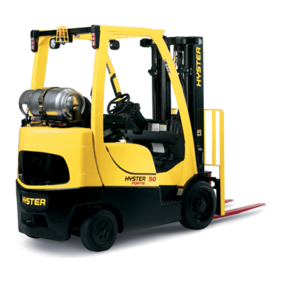
Model Description Model Description COMPONENTS FOR H40-70FT TRUCKS ARE IN SAME LOCATIONS. OVERHEAD GUARD TAIL, BRAKE, AND REVERSE LIGHTS SEAT COUNTERWEIGHT STEERING AXLE SEAT BELT AND HIP RESTRAINT DRIVE AXLE CARRIAGE FORKS LOAD BACKREST EXTENSION PARKING BRAKE STEERING WHEEL MAST OPERATING MANUAL (BEHIND SEAT) Figure 1. -
Page 13: General
Model Description Model Description General • A MONOTROL® pedal that controls both the forward and reverse operation of the powershift transmission and This Operating Manual is for the following models of lift the speed of the engine. trucks: • A Direction Control Lever on the left side of the Display S40FT, S50FT, S55FTS, S60FT, and S70FT (F187) Switch Cluster that controls the forward, neutral, and reverse operation of the powershift transmission. - Page 14 Model Description If your lift truck is an H40-70FT (L177) with manual hydraul- This emergency lowering valve (see Figure 15) allows the ics and manufactured prior to March, 2009, is it not equip- operator or service technician to lower the lift truck's mast ped with an emergency lowering valve.
- Page 15 Model Description Table 1. Transmissions Operational Basic Powershift or DuraMatch Transmission Feature Powershift 1 Speed Transmission Electronic Inching Electronic Control of Direction Changes Auto Deceleration – Controlled Power Reversal – Roll Reduction Feature – Roll Back Feature – Reduced Drive Tire Slippage –...
-
Page 16: Operator Protection Equipment
Model Description not be considered a substitute for good judgment and care when handling loads. Do not remove the overhead guard. NOTE: The seat belt can be either black or red. The SEAT BELT AND HIP RESTRAINT provide additional means to help the operator keep the head and torso sub- stantially within the confines of the lift truck frame and over- head guard if a tipover occurs. -
Page 17: Nameplate
Model Description Nameplate When a lift truck is shipped incomplete from the factory, the Nameplate is covered by an INCOMPLETE label as shown in Figure 3. If the equipment on the truck is changed, the WARNING Nameplate is covered by a NOTICE label as shown in Fig- DO NOT add to or modify the lift truck. -
Page 18: Safety Labels
Model Description Safety Labels Safety labels are installed on the lift truck to provide infor- mation about possible hazards. It is important that all safety labels are installed on the lift truck and can be read. See Figure 4. All possible label configurations that can be on the lift trucks covered in this Operating Manual are not shown in Figure 4. - Page 19 Model Description LABELS FOR H40-70FT TRUCKS ARE IN SAME LOCATIONS. Figure 4. Warning and Safety Labels (Sheet 1 of 3)
- Page 20 Model Description SEE THE PARTS MANUAL FOR THE PART NUMBER. Figure 4. Warning and Safety Labels (Sheet 2 of 3)
- Page 21 Model Description SEE THE PARTS MANUAL FOR THE PART NUMBER. Figure 4. Warning and Safety Labels (Sheet 3 of 3)
- Page 22 Model Description Legend for Figure 4 FLAMMABLE LP-GAS MAST WARNING LPG TANK WARNING TIPOVER WARNING OPTIONAL FIRE SAFETY RATING BRAKE FLUID WARNING (PNEUMATIC OVERHEAD GUARD LABEL FAN WARNING TRUCKS ONLY) WARNING, OPERATION JOYSTICK LABEL LOCKING GAS SPRING NO RIDERS DIESEL FUEL LABEL (NOT SHOWN) HOOD OPENING CAUTION WARNING FOR PARKING BRAKE UNLEADED FUEL LABEL (NOT...
-
Page 23: Display Switch Cluster
Model Description Display Switch Cluster Display Switch Cluster – Right-Side Display Inputs WARNING The lift trucks covered in this manual can have several dif- If any of the instruments, levers, or pedals do not oper- ferent options and configurations. Depending on the equip- ate as described in the following tables, report the ment on the lift truck, warning and indicator lights on the problem immediately. - Page 24 Model Description LEFT SIDE DISPLAY INPUTS LCD SCREEN RIGHT SIDE DISPLAY INPUTS WARNING AND INDICATOR LIGHTS Figure 5. Display Switch Cluster...
- Page 25 Model Description LEFT SIDE DISPLAY – CAB OPTION H40-70FT ONLY RIGHT SIDE DISPLAY Figure 6. Display Switch Cluster...
- Page 26 Model Description Table 2. Display Switch Cluster – Right-Side Display Inputs (See Figure 6) Item Item Function Power ON/OFF If the lift truck is equipped with the keyless start option, lift truck system power is turned ON by pressing this button. To turn the lift truck system power and engine OFF, press the Power ON/OFF button again.
- Page 27 Model Description Table 2. Display Switch Cluster – Right-Side Display Inputs (See Figure 6) (Continued) Item Item Function #2 Button If the lift truck is equipped with front work lights, the #2 Button and the Front Work Light button will share space on the Display Switch Cluster. When an operator or supervisor are in the main menu for entering and administering passwords, the Front Work Lights function is disabled and the button is enabled to enter the number 2 for password purposes.
- Page 28 Model Description Table 2. Display Switch Cluster – Right-Side Display Inputs (See Figure 6) (Continued) Item Item Function Scroll Down This button is used for the following functions: • Decreasing the value of a selected operating function • Scrolling downward through a list of possible menu selections #4 Button The Scroll Down and #4 Button share the same space on the Display Switch Cluster.
- Page 29 Model Description Table 2. Display Switch Cluster – Right-Side Display Inputs (See Figure 6) (Continued) Item Item Function Hourmeter On trucks with key switch start, when truck is ON, engine hours will be displayed on LCD screen on right side of second line. When truck is OFF, press hourmeter button to display engine hours.
-
Page 30: Display Switch Cluster - Lcd Screen And Warning And Indicator Lights
Model Description Display Switch Cluster – LCD Screen and coolant temperature and fuel level displays. If a fault occurs, the fault number will be displayed on the top line. Warning and Indicator Lights The time of day is displayed on the right side of the top line The LCD screen (see Figure 7) shows operator messages at all times during the selection of displayed text. - Page 31 Model Description LCD SCREEN WARNING AND INDICATOR LIGHTS Figure 7. Display Switch Cluster – LCD Screen and Warning and Indicator Lights...
- Page 32 Model Description Table 3. Instruments – Warning and Indicator Lights (See Figure 7) Item No. Item Function Indicator Light Left This green indicator will blink on and off when the left turn signal is selected. Not Turn Signal on at Start Check. Warning Light, This amber indicator is on when the system is in the ON state, and turns off as the Engine...
- Page 33 Model Description Table 3. Instruments – Warning and Indicator Lights (See Figure 7) (Continued) Item No. Item Function Warning Light, CAUTION Brake Fluid Level Do not continue to operate the lift truck if the light is on during operation. Malfunction Indicator The red brake fluid light will illuminate when the brake fluid level switch indicates a low fluid condition.
- Page 34 Model Description Table 3. Instruments – Warning and Indicator Lights (See Figure 7) (Continued) Item No. Item Function Indicator Light This green indicator will blink on and off when the right turn signal is selected. Not Right Turn Signal on at Start Check. Warning Light, CAUTION Transmission...
- Page 35 Model Description Table 3. Instruments – Warning and Indicator Lights (See Figure 7) (Continued) Item No. Item Function Warning Light, CAUTION Engine Oil Stop the engine immediately if the red light is ON while the engine is run- Pressure ning. Malfunction Indicator The red light will illuminate when the system is not in the OFF state and the oil...
- Page 36 Model Description Table 3. Instruments – Warning and Indicator Lights (See Figure 7) (Continued) Item No. Item Function Warning Light, CAUTION Engine Coolant Do not continue to operate the lift truck if the light is on during operation. Temperature Malfunction If this red light illuminates while the engine is running, it indicates the engine cool- Indicator ant temperature has reached 110 °C (230 °F) or above.
- Page 37 Model Description Table 3. Instruments – Warning and Indicator Lights (See Figure 7) (Continued) Item No. Item Function Warning Light, CAUTION Coolant Level Do not continue to operate the lift truck if the light is on during operation. in Radiator Malfunction If the lift truck is equipped with the premium monitoring package, this red warning Indicator...
- Page 38 Model Description Table 3. Instruments – Warning and Indicator Lights (See Figure 7) (Continued) Item No. Item Function Warning Light, CAUTION Fuel Level Do not allow the lift truck to run out of LPG. Damage to the catalytic con- Indicator verter can result.
-
Page 39: Operator Controls
Model Description Table 3. Instruments – Warning and Indicator Lights (See Figure 7) (Continued) Item No. Item Function Indicator Light This amber indicator light will illuminate if the fuel-water separator sensor indicates Water Separator that water must be drained. Not on at Start Check. (Diesel Only) Operator Controls (See Table 4 and Figure 8) - Page 40 Model Description SEE FIGURE 9 FOR MORE OPERATOR COMPARTMENT PEDAL CONFIGURATIONS. Figure 8. Operator Controls (Sheet 1 of 2)
- Page 41 Model Description Figure 8. Operator Controls (Sheet 2 of 2)
- Page 42 Model Description Legend for Figure 8 UNITS WITH MONOTROL® PEDAL UNITS BUILT AFTER JANUARY, 2010 WITH E-HYDRAULICS. UNITS WITH DIRECTION CONTROL LEVER...
- Page 43 Model Description INCHING/BRAKE PEDAL INCHING/BRAKE PEDAL PEDAL BRAKE PEDAL ACCELERATOR PEDAL Figure 9. Operator Compartment Pedal Configurations...
- Page 44 Model Description Table 4. Operator Controls (See Figure 8) Item Item Function Steering Wheel The steering wheel controls the position of the steer tires. Inching/Brake Pedal By varying the position of the inching/brake pedal, the operator can move the lift truck slowly while a high engine speed is used for lifting loads.
- Page 45 Model Description Table 4. Operator Controls (See Figure 8) (Continued) Item Item Function Lever For Steering Column Tilt To move the steering column up, pull up on the tilt lever and the steering column moves up. Release the lever when the steering column reaches the desired posi- tion.
- Page 46 Model Description Table 4. Operator Controls (See Figure 8) (Continued) Item Item Function Parking Brake Lever WARNING Correct adjustment is necessary to provide adequate braking. See the Main- tenance section for adjustment procedures. Always apply the parking brake when leaving the lift truck. NOTE: There is a sensor in the seat that actuates an audible alarm.
- Page 47 Model Description Table 4. Operator Controls (See Figure 8) (Continued) Item Item Function Inching/Brake By varying the position of the inching/brake pedal, the operator can move the lift Pedal truck slowly while a high engine speed is used for lifting loads. Completely depressing the pedal disengages the transmission and applies the service brakes.
- Page 48 Model Description Table 4. Operator Controls (See Figure 8) (Continued) Item Item Function Lift/Lower Control NOTE: Manual hydraulic control levers are standard on the trucks covered in this Lever manual (see Figure 8). Two optional controls are available for the hydraulic func- tions: electronic hydraulic mini-levers (see Figure 8) and a joystick (see Figure 10 and Table 5).
- Page 49 Model Description Table 4. Operator Controls (See Figure 8) (Continued) Item Item Function Tilt Control Lever NOTE: Manual hydraulic control levers are standard on the trucks covered in this manual (see Figure 8). Two optional controls are available for the hydraulic func- tions: electronic hydraulic mini-levers (see Figure 8) and a joystick (see Figure 10 and Table 5).
- Page 50 Model Description Table 4. Operator Controls (See Figure 8) (Continued) Item Item Function Tilt Control Lever These trucks can be equipped with the Return to Set Tilt (RTST) option if truck (Cont) has electronic hydraulic mini-levers. The RTST option automatically stops the tilt function at a set point.
- Page 51 Model Description Table 4. Operator Controls (See Figure 8) (Continued) Item Item Function Manual Control Lever for WARNING Auxiliary Hydraulic A manual control lever with a detent must be installed when an attachment Functions (3rd lever). with a clamp is installed. See your dealer for lift trucks to get the correct See Figure 8.
- Page 52 Model Description Table 4. Operator Controls (See Figure 8) (Continued) Item Item Function Electronic Control Mini-Lever The third electronic control mini-lever is installed to the right of the electronic tilt for Auxiliary Hydraulic Func- control lever. This lever can have two methods of operation, depending on the tions (3rd lever).
- Page 53 Model Description Table 4. Operator Controls (See Figure 8) (Continued) Item Item Function Manual Control Lever for NOTE: Manual hydraulic control levers are standard on the trucks covered in this Auxiliary Hydraulic manual (see Figure 8). Two optional controls are available for the hydraulic func- Functions (4th lever).
- Page 54 Model Description Table 4. Operator Controls (See Figure 8) (Continued) Item Item Function Electronic Control Mini-Lever The fourth electronic control lever is installed to the right of the third electronic for Auxiliary Hydraulic Func- control lever. This lever can have two methods of operation, depending on the tions (4th lever).
- Page 55 Model Description Table 4. Operator Controls (See Figure 8) (Continued) Item Item Function Direc- NOTE: There is a sensor in the seat that actuates an audible buzzer. If the opera- tion tor leaves the seat with the key switch ON and the lever is not in NEUTRAL, the Con- buzzer will pulse ON and OFF for 10 seconds.
- Page 56 Model Description Table 4. Operator Controls (See Figure 8) (Continued) Item Item Function Key Switch NOTE: There is no mechanical lockout that prevents the key switch from being returned to the START position without first being returned to the OFF position. However, the Vehicle System Manager (VSM) software prevents the starter motor from being energized while the engine is running.
- Page 57 Model Description Table 4. Operator Controls (See Figure 8) (Continued) Item Item Function Accelerator Pedal This pedal controls the speed of the engine and is operated by the operator's right foot. It is used on units that have a Direction Control Lever. Joystick The lift trucks in this manual can be equipped with an optional joystick to control the hydraulic functions.
- Page 58 Model Description Table 4. Operator Controls (See Figure 8) (Continued) Item Item Function Auxiliary Auxiliary horn button functions when the key or keyless ignition is in the ON posi- Horn tion and up to 20 minutes after the key or keyless ignition is turned to the OFF Button position.
-
Page 59: Operator Controls - Joystick Features
Model Description Operator Controls – Joystick Features (See Table 5 and Figure 10) WARNING If any of the controls, instruments, levers, or pedals do not operate as described in the following tables, report the problem immediately. DO NOT operate the vehicle until the problem is corrected. - Page 60 Model Description Table 5. Operator Controls – Joystick Features (See Figure 10) Item Item Function Lift/Lower NOTE: To operate the joystick, the operator must be on the seat. Function Push the joystick lever forward to lower the carriage and forks. Pull the joystick lever A.
- Page 61 Model Description Table 5. Operator Controls – Joystick Features (See Figure 10) (Continued) Item Item Function Tilt Function NOTE: To operate the joystick, the operator must be on the seat. Move the joystick lever to the left to tilt the mast backward. Move the joystick lever to the right to tilt the mast forward.
- Page 62 Model Description Table 5. Operator Controls – Joystick Features (See Figure 10) (Continued) Item Item Function 2, 4 Auxiliary This rocker switch will control either Function 3 or Functions 3 and 4, depending on Hydraulic the attachment. Function NOTE: To operate the joystick, the operator must be on the seat. (Left Rocker Switch) NOTE: If the lift truck is equipped with only a three function valve and clamp attach-...
- Page 63 Model Description Table 5. Operator Controls – Joystick Features (See Figure 10) (Continued) Item Item Function 3, 4 Auxiliary This rocker switch will control either Function 4 or Functions 4 and 5, depending on Hydraulic the attachment. Function NOTE: To operate the joystick, the operator must be on the seat. (Right Rocker Switch) NOTE: If the truck is equipped with only a four function valve and clamp attachment,...
- Page 64 Model Description Table 6. Auxiliary Control Levers Direction of Movement Function Load or Equipment Control Lever 1. REACH Retract/Extend Backward/Forward 2. SIDESHIFT Right/Left Backward/Forward 3. PUSH-PULL Backward/Forward Backward/Forward 4. ROTATE Clockwise/Counterclockwise Backward/Forward 5. UPENDER Up/Down Backward/Forward 6. SCOOP Up/Down Backward/Forward 7.
-
Page 65: Operating Procedures
Operating Procedures Operating Procedures General If engines are operated in confined spaces, maintain adequate ventilation or vent exhaust to the outside. Do Know Your Lift Truck not exceed applicable air contaminant limits (see 29 CFR 1910.1000 Table Z-1). WARNING Follow the inspection and maintenance schedule and Always make sure the parking brake is fully applied procedures in this manual. - Page 66 Operating Procedures combustible dust, fibers, or paper and remove any for- The fork lift truck is designed to pickup, move, and tier eign materials. Contact your local dealer for forklift materials. The basic lift truck has a lift mechanism and modifications that may be appropriate in environments forks on the front to engage the load.
-
Page 67: Stability And Center Of Gravity
Operating Procedures This basic principle is used for picking up a load. The ability The lift truck has moving parts and therefore has a CG that of the lift truck to handle a load is discussed in terms of moves. The CG moves forward and back as the mast is til- center of gravity and both forward and side stability. -
Page 68: Capacity (Weight And Load Center)
Operating Procedures operating on uneven surfaces or on an incline. These fac- Capacity (Weight and Load Center) tors must be considered when traveling with an unloaded The capacity of the lift truck is shown on the Nameplate. truck, as well, because an unloaded truck will tip over to The capacity is listed in terms of weight and load center. -
Page 69: Impact Sensor
Operating Procedures the center of gravity of the load. Both the vertical and Impact Detection icon will be displayed on the LCD screen. horizontal load centers are specified on the Nameplate. If the time is set to 0 seconds, the lift truck will shut down right after the impact is detected and no alarm will sound. -
Page 70: Inspection Before Operation
Operating Procedures only do its job when it is in proper working order. If repairs are required, install a tag in the operator's area stating "DO NOT OPERATE" and remove the key from the key switch if truck is equipped with key switch option. -
Page 71: Mounting And Dismounting
Operating Procedures fibers (paper, wood, cotton, agricultural grass/grain, etc). Mounting and Dismounting Remove all foreign materials. WARNING • Coolant level in the cooling system and condition of the To avoid serious injury when entering or exiting the lift drive belts. truck, ALWAYS USE 3 POINTS OF CONTACT. - Page 72 Operating Procedures There are four password types used on these trucks: (see Figure 6 and Table 2) to enter the five digit password and then press the STAR (*) button to enter the password • Operator: Allows operator to operate lift truck. and access main menu.
-
Page 73: Starting Procedures
Operating Procedures Starting Procedures WARNING Gasoline is extremely flammable. Do not start the Do not start or operate the lift truck, engine if a gas leak is detected. including any of its functions or attach- ments, from any place other than the des- NOTE: Lift trucks equipped with Mazda 2007 emission ignated operator's position. - Page 74 Operating Procedures 3. The Engine Control Unit (ECU) will automatically begin a 11. If the truck is equipped with Operator Password feature, warm-up/thaw cycle which preheats select fuel system enter correct operator, supervisor, or service password. components. 12. On trucks equipped with a LPG or gasoline engine, turn 4.
-
Page 75: Starting Procedures, Trucks With Keyless Start Option
Operating Procedures Starting Procedures, Trucks With Keyless equipped with Mazda LPG engine (except Mazda 2007 emission compliant engines). Start Option NOTE: The warm-up/thaw cycle can be bypassed at any- WARNING time by cranking the engine normally. LPG is very flammable. An odor of LPG fuel can indi- 2. -
Page 76: Checks With The Engine Running
Operating Procedures 9. Make sure lift truck hood is closed. Checks With the Engine Running 10. Depress and release the Power ON/OFF button. If lift truck is equipped with a diesel engine and engine is cold, WARNING the cold start indicator light will illuminate and the cold start circuit will be energized. -
Page 77: Load Weighing Sensor
Operating Procedures overhead guard if a tipover occurs. This protection system • Check the oil level in the powershift transmission when is intended to reduce the risk of the head and torso being the oil is at operating temperature 50 °C (120 °F). Turn trapped between the truck and the ground, but it can not the truck off and wait one minute. -
Page 78: Set Load Weight To Zero
Operating Procedures 3. Lower the load 51 mm (2 in.). Stop lowering, wait 1 sec- Certain faults or sensor measurements can cause the truck ond, and read the load weight. This will be the most accu- to go into Engine Shutdown mode. The following actions rate weight. -
Page 79: Operating Techniques
Operating Procedures Engine Start button. If the Engine Start button is pressed Take the lift truck to a service technician immediately for before the Power ON/OFF button, the starter will not oper- repair if it experiences a decrease in performance. ate. -
Page 80: Basic Operating Procedures
Operating Procedures style seat belt. When the ELR seat belt is properly buckled The following discussion lists basic procedures applicable across the operator, the belt will permit slight operator to lift truck operation. repositioning without activating the locking mechanism. If 1. - Page 81 Operating Procedures If a lift truck is used to elevate a must remain at the controls. Watch for overhead worker, a safety platform must obstructions. be attached to the forks and car- 2. NO RIDERS. A lift truck is built for only riage.
- Page 82 Operating Procedures Seat Adjustment for Operator Weight CAUTION A major cause for high Whole Body Vibration is caused by the operator not adjusting the seat to his/her weight. NOTE: It is important to adjust the weight setting for each operator. NOTE: The seat is designed for a maximum weight of 135 kg (298 lb) •...
- Page 83 Operating Procedures Legend for Figure 12 Seat Adjustment for Operator Weight SEAT BELT CAUTION WEIGHT ADJUSTMENT KNOB A major cause for high Whole Body Vibration is caused RIDE POSITION INDICATOR FORWARD/BACKWARD ADJUSTMENT LEVER by the operator not adjusting the seat to his/her weight. BACKREST ANGLE ADJUSTMENT LEVER ARMREST NOTE: It is important to adjust the weight setting for each...
- Page 84 Operating Procedures Figure 13. Seat Adjustment - Full Suspension...
-
Page 85: Driving And Direction Changes
Operating Procedures Legend for Figure 13 STANDARD, NON-SWIVEL SEAT FULL SUSPENSION SWIVEL SEAT SEAT BELT BACKREST ANGLE ADJUSTMENT LEVER WEIGHT ADJUSTMENT KNOB ARMREST RIDE POSITION INDICATOR SWIVEL LATCH RELEASE LEVER FORWARD/BACKWARD ADJUSTMENT LEVER 5. Do not drive a lift truck into an elevator unless authorized 6. - Page 86 Operating Procedures Table 7. Transmissions Basic Powershift or Operational Feature DuraMatch Transmission Powershift 1 Speed Transmission Electronic Inching Electronic Control of Direction Changes Auto Deceleration – Controlled Power Reversal – Roll Reduction Feature – Roll Back Feature – Reduced Drive Tire Slippage –...
-
Page 87: General
Operating Procedures the front of the lift truck to go FORWARD and toward the rear of the lift truck to go in REVERSE. Normal Operations In normal operating conditions, either at start or while driv- ing, the lift truck can only be maintained at a stopped posi- tion by applying the service brake or parking brake. -
Page 88: Standard Operator Presence System
Operating Procedures Standard Operator Presence System tor leaves the seat of the lift truck with the engine running and without applying the parking brake. WARNING If the lift truck is equipped with a Direction Control Lever Always make sure the parking brake is fully applied and the operator leaves the seat without engaging the before leaving the lift truck. -
Page 89: Optional Operator Presence System
Operating Procedures Optional Operator Presence System parking brake before getting off the seat, the seat switch will disengage the transmission and disable the hydraulic WARNING mast functions. ALWAYS make sure the parking brake is fully applied When the operator returns to the seat, if it was not set, the before leaving the lift truck. -
Page 90: Duramatch
The factory settings for the Controlled Power Reversal The drive train can be damaged if the lift truck is travel- feature can be changed by a Hyster Service Technician ing too fast when the controls are changed to the when required to meet special application require- opposite direction of travel. - Page 91 The factory settings for the Auto-Deceleration Feature Provides limited transmission braking to stop the lift truck can be changed by a Hyster Service Technician when from rolling on level ground or to limit vehicle speeds to required to meet special application requirements.
-
Page 92: Inching
Operating Procedures Roll Back Feature Inching is the movement of a lift truck that allows a slow travel speed while keeping the engine speed high for fast If the operator uses the brakes to bring the lift truck, regard- operation of the lift mechanism. less of direction selected, to a stop on a grade;... -
Page 93: Steering (Turning)
Operating Procedures Steering (Turning) ground will aggravate these conditions and cause the fork- lift to become unstable. WARNING WARNING TRAVEL SLOWLY WHEN TURN- Failure to observe the tail swing area when making a ING. Lift trucks can tip over even turn can injure or kill someone. -
Page 94: Load Handling, General
Operating Procedures the tail swing area when making a turn can lead to injury or Load Handling, General death. 1. The capacity is the maximum Do not turn on an incline. To reduce load that the lift truck can handle for the possibility of a tipover, a lift truck the load condition shown on the must not be driven across an incline. -
Page 95: Load Handling, Lifting, Lowering, And Tilting
Operating Procedures If the weight of the load is not centered between the forks, WARNING the load can fall from the forks when you turn a corner or Do not handle a load if hit a bump. An off-center load will increase the possibility of any loose part of it is the truck tipping over to the side. - Page 96 Operating Procedures NEUTRAL position, the faster the speed of the hydraulic A lift truck without an overhead guard provides no such function. protection and other personnel have no overhead protec- tion. Avoid hitting objects such as stacked material that Do not lift or hit anything that can fall on the operator or a could become dislodged and fall.
- Page 97 Operating Procedures WARNING NEVER put hands, arms, head, or legs through the mast or near the carriage or lift chains. This warning applies not only to the operator but also a helper. A helper must not be near the load or lift mechanism while the operator is attempting to handle a load.
-
Page 98: Load Handling, How To Engage And Disengage A Load
Operating Procedures IF THE LIFT TRUCK TIPS OVER, DO NOT JUMP OFF! Approach the load carefully. Make sure that the truck is HOLD FIRMLY TO STEERING WHEEL, BRACE YOUR perpendicular to the load. Raise the forks to the proper FEET, AND LEAN FORWARD AND AWAY FROM POINT height for engaging the load. - Page 99 Operating Procedures 3. When a load is put on the floor, tilt the mast forward to a vertical position and lower the load. Tilt the mast forward to permit smooth removal of the forks. Carefully move the lift truck backward to remove the forks from under the load. A.
- Page 100 Operating Procedures IF THE LIFT TRUCK TIPS OVER EITHER TO THE SIDE WARNING OR FORWARD, DO NOT JUMP OFF! HOLD FIRMLY TO Move carefully and smoothly when the load is raised STEERING WHEEL, BRACE YOUR FEET, AND LEAN over a stack. When the load is elevated the center of FORWARD AND AWAY FROM THE POINT OF IMPACT.
-
Page 101: Load Handling, Traveling
Operating Procedures NOTE: Not every load can be lifted using only the forks of a lift truck. Some loads will require a special attachment. 6. When lifting round objects, use a block behind the object. Tilt the mast forward so that the forks can slide along the floor under the object to be lifted. - Page 102 Operating Procedures Always look in the direction of travel to avoid damage to something or injury to someone. 3. For better visibility with large loads, travel with the load trailing, but always keep a proper lookout in the direction of travel.
- Page 103 Operating Procedures 6. Anytime the lift truck is moving 8. Watch clearances, especially forks, mast, overhead keep arms, legs, etc., inside the guard, and tail swing. A lift truck is designed to perform a operator's compartment. Arms and wide variety of functions within limited space. legs outside the machine can be injured when passing obstructions.
- Page 104 Operating Procedures 10. Do not pass another lift truck traveling in the same run off the edge of the travel surface onto soft ground, the direction at intersections, blind spots, or at other dangerous lift truck can tip over. locations. 12.
-
Page 105: Load Handling, Emergency Load Lowering
Operating Procedures Load Handling, Emergency Load Lowering NOTE: The emergency load lowering valve is to be used ONLY if the electrical signal to the main control valve has been disrupted and there is a load lifted. WARNING On trucks equipped with an electronic hydraulic con- To use the emergency load lowering valve, follow these trol valve, when the electronic signal to the mini-levers steps:... - Page 106 Operating Procedures EMERGENCY LOAD LOWERING VALVE COWL WELDMENT MAIN CONTROL VALVE KICK PANEL Figure 15. Emergency Load Lowering Valve...
-
Page 107: Highway Trucks, Rail Cars, And Docks
Operating Procedures Highway Trucks, Rail Cars, and Docks • DO NOT use a lift truck to open or close the door on a rail car unless the lift truck has an attachment that is specifically designed for opening and closing rail car WARNING doors and the operator is trained in its use. -
Page 108: Attachments
Operating Procedures • Make sure that the rail car brakes are set and the wheels Attachments are blocked while loading or unloading. Do this check so NOTE: Make sure the Nameplate is correct if an attach- that the rail car will not move due to the movement of the ment has been installed. -
Page 109: Disconnecting Attachment Hydraulic Quick-Disconnect Hoses
Operating Procedures Disconnecting Attachment Hydraulic Quick- Disconnect Hoses NOTE: Step 1 through Step 4 is to be used for lift trucks equipped with electro-hydraulics. 1. Turn the key switch or keyless switch to the OFF posi- tion. 2. Disconnect the negative terminal of the battery. NOTE: If the Quick-Disconnect hose connectors cannot be disconnected, repeat Step 3 and Step 4. -
Page 110: Connecting Attachment Hydraulic Quick-Disconnect Hoses
Operating Procedures 6. Disconnect the negative terminal of the battery. 5. Connect the Quick-Disconnect hose connectors. 7. Move the manual hydraulic levers forward and backward 6. Connect the negative terminal of the battery. to relieve the system hydraulic pressure. 7. Turn the key switch or keyless switch to the ON position 8. -
Page 111: Parking
Operating Procedures Parking 6. Check engine compartment, if operating in areas con- taining combustible material, and remove foreign debris. The operator must never leave a lift truck in a condition so See FIRE HAZARD WARNING at the beginning of this that it can cause damage and injury. -
Page 112: Maintenance
Maintenance Maintenance General This section contains a Maintenance Schedule and the instructions for maintenance and inspection. WARNING The Maintenance Schedule has time intervals for inspec- Do not make modifications to the lift truck that affect tion, lubrication, and maintenance for your lift truck. The the safe operation of the lift truck. -
Page 113: Serial Number Data
Maintenance inspection, lubrication, and maintenance will help your lift The lift truck must be towed on a slope. truck provide more efficient performance and operate for a If the engine cannot run, there is no power available for longer period of time. the hydraulic steering system. -
Page 114: How To Put A Lift Truck On Blocks
Maintenance 3. Using a lift truck or a lifting device that can be attached put additional blocks in the following positions to to the mast (I.E. come-a-long), raise the carriage and forks maintain stability: approximately 30 cm (12 in.) from surface. Install a chain Before removing the mast and drive axle, put blocks around a mast crossmember and the carriage, to prevent under the counterweight so that the lift truck cannot fall... -
Page 115: How To Raise The Steering Tires
Maintenance 3. Tilt the mast fully forward until the drive tires are raised How to Clean a Lift Truck from the surface. CAUTION 4. Put additional blocks under the frame behind the drive Your lift truck may be damaged if water or cleaning tires. -
Page 116: Maintenance Schedule
Maintenance Schedule DRIVE TIRES STEERING TIRES Figure 17. Put a Lift Truck on Blocks Maintenance Schedule... - Page 117 Maintenance Schedule Figure 18. GM 2.4L Gas Engine (Prior to January, 2011) Maintenance and Lubrication Points...
- Page 118 Maintenance Schedule Figure 19. GM 2.4L Gas Engine (After January, 2011) Maintenance and Lubrication Points...
- Page 119 Maintenance Schedule Figure 20. GM 2.4L LPG Engine (Prior to January, 2011) Maintenance and Lubrication Points...
- Page 120 Maintenance Schedule Figure 21. GM 2.4L LPG Engine (After January, 2011) Maintenance and Lubrication Points...
- Page 121 Maintenance Schedule Figure 22. Mazda 2.0L and 2.2L Gas Engine (Except 2007 Emission Compliant Engines) Maintenance and Lubrication Points...
- Page 122 Maintenance Schedule Figure 23. Mazda 2.0L and 2.2L Gas Engine (2007 Emission Compliant Engines Only) Maintenance and Lubrication Points...
- Page 123 Maintenance Schedule Figure 24. 2010 Mazda 2.0L and 2.2L Gas Engine With Aluminum Case Transmission (Prior to January, 2011) Maintenance and Lubrication Points...
- Page 124 Maintenance Schedule Figure 25. Mazda 2.0L and 2.2L Gas Engine With Aluminum Case Transmission (After January, 2011) Maintenance and Lubrication Points...
- Page 125 Maintenance Schedule Figure 26. Mazda 2.0L and 2.2L LPG Engine (Except 2007 Emission Compliant Engines) Maintenance and Lubrication Points...
- Page 126 Maintenance Schedule Figure 27. Mazda 2.0L and 2.2L LPG Engine (2007 Emission Compliant Engines Only) Maintenance and Lubrication Points...
- Page 127 Maintenance Schedule Figure 28. 2010 Mazda 2.0L and 2.2L LPG Engine With Aluminum Case Transmission (Prior to January, 2011) Maintenance and Lubrication Points...
- Page 128 Maintenance Schedule Figure 29. Mazda 2.0L and 2.2L LPG Engine With Aluminum Case Transmission (After January, 2011) Maintenance and Lubrication Points...
- Page 129 Maintenance Schedule Figure 30. Yanmar 2.6L and 3.3L Diesel Engine (Prior to January, 2011) Maintenance and Lubrication Points...
- Page 130 Maintenance Schedule Figure 31. Yanmar 2.6L and 3.3L Diesel Engine With Aluminum Case (After January, 2011) Maintenance and Lubrication Points...
- Page 131 Maintenance Schedule Maintenance Schedule Table 8. (See Figure 18 Through Figure 31) 8 Hr/ 250 Hr/ 500 Hr/ 1000 Hr/ 2000 Hr/ 4000 Hr/ Procedure or Item No. Item Specification 1 Day 6 Mo 6 Mo 6 Mo 1 Yr 2 Yr Quantity TIRES...
- Page 132 Maintenance Schedule Table 8. (See Figure 18 Through Figure 31) (Continued) 8 Hr/ 250 Hr/ 500 Hr/ 1000 Hr/ 2000 Hr/ 4000 Hr/ Procedure or Item No. Item Specification 1 Day 6 Mo 6 Mo 6 Mo 1 Yr 2 Yr Quantity ENGINE COMPARTMENT Remove...
- Page 133 Maintenance Schedule Table 8. (See Figure 18 Through Figure 31) (Continued) 8 Hr/ 250 Hr/ 500 Hr/ 1000 Hr/ 2000 Hr/ 4000 Hr/ Procedure or Item No. Item Specification 1 Day 6 Mo 6 Mo 6 Mo 1 Yr 2 Yr Quantity FUEL TANK (GAS) 52 liter...
- Page 134 Maintenance Schedule Table 8. (See Figure 18 Through Figure 31) (Continued) 8 Hr/ 250 Hr/ 500 Hr/ 1000 Hr/ 2000 Hr/ 4000 Hr/ Procedure or Item No. Item Specification 1 Day 6 Mo 6 Mo 6 Mo 1 Yr 2 Yr Quantity TRANSMISSION Check...
- Page 135 Maintenance Schedule Table 8. (See Figure 18 Through Figure 31) (Continued) 8 Hr/ 250 Hr/ 500 Hr/ 1000 Hr/ 2000 Hr/ 4000 Hr/ Procedure or Item No. Item Specification 1 Day 6 Mo 6 Mo 6 Mo 1 Yr 2 Yr Quantity ENGINE OIL 3.9 liter...
- Page 136 Maintenance Schedule Table 8. (See Figure 18 Through Figure 31) (Continued) 8 Hr/ 250 Hr/ 500 Hr/ 1000 Hr/ 2000 Hr/ 4000 Hr/ Procedure or Item No. Item Specification 1 Day 6 Mo 6 Mo 6 Mo 1 Yr 2 Yr Quantity ENGINE OIL 5.0 liter...
- Page 137 Maintenance Schedule Table 8. (See Figure 18 Through Figure 31) (Continued) 8 Hr/ 250 Hr/ 500 Hr/ 1000 Hr/ 2000 Hr/ 4000 Hr/ Procedure or Item No. Item Specification 1 Day 6 Mo 6 Mo 6 Mo 1 Yr 2 Yr Quantity ENGINE OIL 10.2 liter...
- Page 138 Maintenance Schedule Table 8. (See Figure 18 Through Figure 31) (Continued) 8 Hr/ 250 Hr/ 500 Hr/ 1000 Hr/ 2000 Hr/ 4000 Hr/ Procedure or Item No. Item Specification 1 Day 6 Mo 6 Mo 6 Mo 1 Yr 2 Yr Quantity AIR FILTER 1 Filter...
- Page 139 Maintenance Schedule Table 8. (See Figure 18 Through Figure 31) (Continued) 8 Hr/ 250 Hr/ 500 Hr/ 1000 Hr/ 2000 Hr/ 4000 Hr/ Procedure or Item No. Item Specification 1 Day 6 Mo 6 Mo 6 Mo 1 Yr 2 Yr Quantity LPG REGULATOR Drain Tar.
- Page 140 Maintenance Schedule Table 8. (See Figure 18 Through Figure 31) (Continued) 8 Hr/ 250 Hr/ 500 Hr/ 1000 Hr/ 2000 Hr/ 4000 Hr/ Procedure or Item No. Item Specification 1 Day 6 Mo 6 Mo 6 Mo 1 Yr 2 Yr Quantity ENGINE IDLE SPEED See NOTE 5.
- Page 141 Maintenance Schedule Table 8. (See Figure 18 Through Figure 31) (Continued) 8 Hr/ 250 Hr/ 500 Hr/ 1000 Hr/ 2000 Hr/ 4000 Hr/ Procedure or Item No. Item Specification 1 Day 6 Mo 6 Mo 6 Mo 1 Yr 2 Yr Quantity VALVE ADJUSTMENT Adjust as...
- Page 142 Maintenance Schedule Table 8. (See Figure 18 Through Figure 31) (Continued) 8 Hr/ 250 Hr/ 500 Hr/ 1000 Hr/ 2000 Hr/ 4000 Hr/ Procedure or Item No. Item Specification 1 Day 6 Mo 6 Mo 6 Mo 1 Yr 2 Yr Quantity LPG FUEL INJECTOR 1 Filter...
- Page 143 Maintenance Schedule Table 8. (See Figure 18 Through Figure 31) (Continued) 8 Hr/ 250 Hr/ 500 Hr/ 1000 Hr/ 2000 Hr/ 4000 Hr/ Procedure or Item No. Item Specification 1 Day 6 Mo 6 Mo 6 Mo 1 Yr 2 Yr Quantity IN-LINE FUEL FILTER 1 Filter...
- Page 144 Maintenance Schedule Table 8. (See Figure 18 Through Figure 31) (Continued) 8 Hr/ 250 Hr/ 500 Hr/ 1000 Hr/ 2000 Hr/ 4000 Hr/ Procedure or Item No. Item Specification 1 Day 6 Mo 6 Mo 6 Mo 1 Yr 2 Yr Quantity SPARK PLUGS Check Plug...
- Page 145 Maintenance Schedule Table 8. (See Figure 18 Through Figure 31) (Continued) 8 Hr/ 250 Hr/ 500 Hr/ 1000 Hr/ 2000 Hr/ 4000 Hr/ Procedure or Item No. Item Specification 1 Day 6 Mo 6 Mo 6 Mo 1 Yr 2 Yr Quantity TRANSMISSION OIL 20 liter...
- Page 146 Maintenance Schedule Table 8. (See Figure 18 Through Figure 31) (Continued) 8 Hr/ 250 Hr/ 500 Hr/ 1000 Hr/ 2000 Hr/ 4000 Hr/ Procedure or Item No. Item Specification 1 Day 6 Mo 6 Mo 6 Mo 1 Yr 2 Yr Quantity LIFT CHAINS Lubricate as...
- Page 147 Maintenance Schedule Table 8. (See Figure 18 Through Figure 31) (Continued) 8 Hr/ 250 Hr/ 500 Hr/ 1000 Hr/ 2000 Hr/ 4000 Hr/ Procedure or Item No. Item Specification 1 Day 6 Mo 6 Mo 6 Mo 1 Yr 2 Yr Quantity TILT CYLINDER ENDS 4 Fittings...
- Page 148 STEERING AXLE 4 Fittings Multipurpose Grease Spindle Bearings See NOTE 9. S40-70FT, S55FTS (F187) PEDALS, LEVERS, SEAT Lubricate as Hyster Part No. 328388 RAILS, CABLES, HINGES, Necessary. LINKAGES, HOOD LATCH SERVICE BRAKES Check Lining 1.0 mm (0.040 in.) Dry Brakes Thickness.
- Page 149 Maintenance Schedule Table 8. (See Figure 18 Through Figure 31) (Continued) 8 Hr/ 250 Hr/ 500 Hr/ 1000 Hr/ 2000 Hr/ 4000 Hr/ Procedure or Item No. Item Specification 1 Day 6 Mo 6 Mo 6 Mo 1 Yr 2 Yr Quantity TRANSMISSION OIL 20 liter...
- Page 150 (dust and waste paper); chemical or abrasive compounds; poor ground conditions; intensive usage at high perform- ance levels; or other abnormal conditions will require more frequent servicing. At your request, your Hyster dealer will advise you of the appropriate serv- ice intervals based on an application survey.
- Page 151 Maintenance Schedule Table 8. (See Figure 18 Through Figure 31) (Continued) 8 Hr/ 250 Hr/ 500 Hr/ 1000 Hr/ 2000 Hr/ 4000 Hr/ Procedure or Item No. Item Specification 1 Day 6 Mo 6 Mo 6 Mo 1 Yr 2 Yr Quantity NOTE 13: Do not open the air filter canister except to change the air filter element.
-
Page 152: Maintenance Procedures Every 8 Hours Or Daily
Maintenance Maintenance Procedures Every 8 Hours or Daily How to Make Checks With the Engine normal. Clean any oil or fuel spills. Ensure all surfaces are free of oils, lubricants, fuel and organic dust or fibers Stopped (paper, wood, cotton, agricultural grass/grain, etc.). WARNING Tires and Wheels Do not operate a lift truck that needs repairs. - Page 153 Maintenance CHECK FOR DAMAGE (REMOVE NAILS, GLASS AND OTHER OBJECTS FROM THE TREAD) MAKE SMOOTH EDGES CHECK THE TIRE PRESSURE (PNEUMATIC TIRES) Figure 32. Check the Tires...
-
Page 154: Safety Labels
Maintenance Safety Labels Do not try to correct the alignment of the fork tips by bending the forks or adding shims. If either fork is damaged, replace the forks as a set. WARNING Safety labels are installed on the lift truck to give infor- Never repair damaged forks by heating or welding. - Page 155 Maintenance during operation. Adjust/repair/replace hose/components as necessary. 6. Check that the lift chains are correctly lubricated. Use SAE 30 engine oil to lubricate the lift chains. 7. Inspect the lift chains for cracks or broken links and worn or turned pins. Lift chains must be replaced as a set. See Figure 33.
-
Page 156: Operator Restraint System
Maintenance Operator Restraint System Figure 35. Each item must be checked to make sure it is fastened correctly, functions correctly, and is in good condi- The seat belt, hip restraint, seat, hood, and hood latches tion. are all part of the operator restraint system (seeFigure 34) - Page 157 Maintenance Figure 34. Hood and Seat Check...
- Page 158 Maintenance Legend for Figure 34 NOTE: NON-SWIVEL SEAT SHOWN. AUTOMATIC LOCKING RETRACTOR EMERGENCY LOCKING RETRACTOR LATCH STRIKER ARM REST HOOD LATCH SEAT BELT FORWARD/BACKWARD ADJUSTMENT SEAT HOOD HIP RESTRAINT OPERATOR WEIGHT ADJUSTMENT HOOD HINGE SEAT RAIL...
-
Page 159: Automatic Locking Retractor (Alr)
Maintenance Automatic Locking Retractor (ALR) NOTE: S40-70FT, S55FTS lift trucks produced before November 1, 2005 are equipped with the ALR type seat belts. See Figure 36. The seat belt must fasten securely. Make sure the seat belt extends and retracts smoothly and is not frayed or torn. If the seat belt is damaged or does not operate properly, it must be replaced. -
Page 160: Emergency Locking Retractor (Elr)
Maintenance Emergency Locking Retractor (ELR) pulled from the retractor assembly or the belt will not retract, replace the seat belt assembly. When the ELR style seat belt is properly buckled across the operator, the belt will permit slight operator reposition- •... - Page 161 Maintenance NOTE: SWIVEL SEAT IS AN OPTIONAL FEATURE. AUTOMATIC LOCKING RETRACTOR EMERGENCY LOCKING RETRACTOR FORWARD/BACKWARD ADJUSTMENT OPERATOR WEIGHT ADJUSTMENT SEAT BELT SWIVEL ADJUSTMENT SEAT POSITION ADJUSTMENT (SEAT RAIL) Figure 37. Swivel Seat Controls...
-
Page 162: Engine Compartment
Maintenance Engine Compartment Check for the presence of any combustible material such as paper, leaves etc. Remove any combustible materials. Paper Application Vehicles used in paper applications require regular inspec- tion and cleaning to minimize the risk of fire. This should be done at least once every 8 hours or more frequently depending upon operating environment. - Page 163 Maintenance actually increase the engine temperature because of no Paper removal can generally be accomplished using a heat transfer through the radiator. compressed air line and nozzle. An extension may be help- ful to access hard to reach places. Remove floor plates and With engine OFF and lift truck components cooled, check side covers for better access to engine compartment.
-
Page 164: Fuel, Oil, And Coolant Leaks, Check
Maintenance wraps if they have been removed for some other service Also check the condition of the radiator or heater hoses operation. that are not leaking. Soft or cracked hoses need to be replaced before a major leak occurs. Fuel, Oil, and Coolant Leaks, Check Hydraulic Hoses WARNING Check the condition of the hydraulic hoses for serviceability... -
Page 165: Steering Column Gas Cylinder
Maintenance Steering Column Gas Cylinder Make sure the gas cylinder for the steering column oper- ates correctly. The cylinder must NOT allow the column to move unless the tilt lever is released. See Figure 39. Transmission Check the transmission for leaks, damage, and loose com- ponents. -
Page 166: Hydraulic System Oil
Maintenance Hydraulic System Oil Engine Oil After the engine has stopped, wait one minute before WARNING checking the oil level. See Figure 40, Figure 41, Fig- At operating temperature the hydraulic oil is HOT. Do ure 42, or Figure 43. Keep the oil at the correct level as not permit the hot oil to touch the skin and cause a indicated on the dipstick. - Page 167 Maintenance GAS ENGINE LPG ENGINE DIPSTICK ENGINE OIL ENGINE OIL FILL ENGINE OIL FILTER BATTERY DRIVE BELT PCV VALVE AUXILIARY COOLANT RESERVOIR AIR FILTER SPARK PLUGS RADIATOR CAP FUEL FILTER FUEL INJECTOR Figure 40. Mazda 2.0Land 2.2L Engine Maintenance Points (Except 2007 Emission Compliant Engines)
- Page 168 Maintenance LPG ENGINE GAS ENGINE DIPSTICK ENGINE OIL ENGINE OIL FILL ENGINE OIL FILTER BATTERY DRIVE BELT PCV VALVE AUXILIARY COOLANT RESERVOIR AIR FILTER SPARK PLUGS RADIATOR CAP FUEL FILTER FUEL INJECTOR (GAS ONLY) Figure 41. Mazda 2.0Land 2.2L Engine Maintenance Points (2007 Emission Compliant Engines Only)
- Page 169 Maintenance GAS ENGINE LPG ENGINE DIPSTICK ENGINE OIL RADIATOR CAP AIR FILTER PCV VALVE BATTERY ENGINE OIL FILL FUEL FILTER SPARK PLUGS AUXILIARY COOLANT DRIVE BELT ENGINE OIL FILTER FUEL INJECTOR RESERVOIR Figure 42. GM Engine Maintenance Points...
- Page 170 Maintenance BATTERY AUXILIARY COOLANT RESERVOIR RADIATOR CAP DRIVE BELT AIR FILTER ENGINE OIL FILTER DIPSTICK ENGINE OIL FUEL FILTER FUEL INJECTOR ENGINE OIL FILL Figure 43. Yanmar 2.6L and 3.3L and 3.3L Diesel Engine Maintenance Points...
-
Page 171: Air Filter
Maintenance Air Filter Forks The air filter canister should not be opened until an air filter NOTE: Forks must be removed or installed by trained per- element replacement is required. An air filter element sonnel only. replacement is required when one of the following occurs: The identification of a fork describes how the fork is con- •... - Page 172 Maintenance OUTER FORK CARRIER FORKS INNER FORK CARRIER SIDESHIFT CARRIAGE FORK POSITIONER CAPSCREWS FORK REMOVAL NOTCH Figure 44. Fork Positioner...
- Page 173 Maintenance WARNING Do not try to move a fork without a lifting device. Each hook fork for these lift trucks can weigh 45 to 115 kg (99 to 253 lb). NOTE: Forks are to be replaced only in sets and not indi- vidually.
-
Page 174: Forks, Inspect
Maintenance Forks, Inspect 1. Inspect the forks for cracks and wear. Check that the fork tips are aligned as shown in Figure 47. Check that the bottom of the fork is not worn (Item 4 in Figure 47). 2. Replace any damaged or broken parts that are used to keep the forks locked in position. -
Page 175: Forks, Adjust
Maintenance Forks, Adjust slot, replace with new pin. Adjust the forks as far apart as possible for maximum support of the load. Hook forks will NOTE: During the adjustment of the forks, the heel of the slide along the carriage bars to adjust for the load to be lif- forks should not be touching the ground. - Page 176 Maintenance Fork Tip Alignment Length of Forks 3% Dimension 915 mm (36 in) 27 mm (1.10 in) 1067 mm (42 in) 32 mm (1.26 in) 1220 mm (48 in) 37 mm (1.46 in) 1372 mm (54 in) 41 mm (1.61 in) 1524 mm (60 in) 46 mm (1.81 in) 1830 mm (72 in)
-
Page 177: How To Make Checks With The Engine Running
Maintenance How to Make Checks With the Engine tionary during a check, apply the parking brake and put the transmission in NEUTRAL. Make the checks carefully. Running Indicator Lights, Horn, Fuses, and Relays WARNING If lift truck is equipped with a key switch, turn key to ON DO NOT operate a lift truck that needs repairs. - Page 178 Maintenance NOTE: HOOD REMOVED FOR CLARITY. BATTERY POWER DISTRIBUTION MODULE (PDM) RESISTOR (68 OHM) START RELAY STARTER (30 AMP FUSE) IGNITION 3 RELAY BACKUP RELAY BACKUP (20 AMP FUSE) IGNITION (30 AMP FUSE) SPARE FUEL PUMP (20 AMP FUSE) SPARE FUEL PUMP RELAY BATTERY (25 AMP FUSE) FRONT WORK LIGHT (20 AMP FUSE) FRONT/REAR WORK LIGHT RELAYS...
-
Page 179: Service Brakes
Maintenance Service Brakes There is an indicator light on the Display Switch Cluster for the brake fluid. The red light is ON when the key switch is Brake Fluid Level in the START position or the Power ON/OFF button is pressed, and must go OFF when the engine is running. -
Page 180: Parking Brake
Maintenance Parking Brake grade is a slope that increases 1.5 m in 10 m (1.5 ft increase in 10 ft). Make sure the service brakes are adjusted and the opera- tion of the automatic adjuster mechanism is correct before the parking brake is adjusted. Lift trucks with a pedal: A switch energizes the seat warning circuit when the hand lever is released. -
Page 181: Engine Oil Pressure
Maintenance Engine Oil Pressure Cooling System NOTE: The engine will enter shutdown mode after a warn- WARNING ing buzzer sounds and a 30-second countdown if engine oil DO NOT remove the radiator cap from the radiator pressure is less than 34.5 kPa (5 psi) on lift trucks with when the engine is hot. - Page 182 The coolant will expand as it is heated and the level in the auxiliary coolant reservoir will increase. CAUTION Additives may damage the cooling system. Before using additives, contact your local Hyster dealer. If coolant is added, use the correct mixture of water and ethylene glycol shown in the Maintenance Schedule. WARNING Compressed air can move particles so that they cause injury to the user or to other personnel.
-
Page 183: Steering System
Maintenance Steering System parts of the mast are completely lowered and the engine is STOPPED. WARNING If the mast cannot be lowered, use chains on the mast The lift truck has hydraulic power steering. The steer- weldments and carriage so that they can not move. ing can be difficult if the engine is not running. -
Page 184: How To Add Fuel To The Lift Truck
Maintenance 3. The inner weldments and the carriage must lower com- ON/OFF button, if truck is equipped with keyless start pletely. option. The operator must be off of the lift truck while fuel is added. 4. Raise the mast 1 m (3 ft) with a capacity load. The inner weldments and the carriage must raise smoothly. -
Page 185: Liquefied Petroleum Gas (Lpg)
Maintenance Liquefied Petroleum Gas (LPG) WARNING LPG tanks are heavy. The weight of an LPG tank can WARNING exceed the maximum recommended weight for safe lift- Close the fuel valve on the tank when the lift truck is ing by an individual. Get assistance when lifting or low- not in active use. -
Page 186: Lpg Tank, Remove
Maintenance LPG Tank, Remove 3. Run the engine until it stops, then turn the key switch to the OFF position if truck is equipped with key switch, or NOTE: The LPG tank bracket used on this line of trucks to press the Power ON/OFF button if truck is equipped with mount the LPG tank onto the counterweight comes in two keyless start option. - Page 187 Maintenance Figure 51. LPG Tank and Bracket...
-
Page 188: Lpg Tank, Fill
Maintenance Legend for Figure 51 SWING OUT BRACKET EZXCHANGE TANK BRACKET LPG TANK STOP PIN TANK STRAP BRACKET HANDLE QUICK DISCONNECT FITTING BRACKET PIVOT HYDROSTATIC RELIEF VALVE GAS SPRING () MANIFOLD BLOCK BRACKET RELEASE PIN ALIGNMENT PIN LPG Tank, Fill 2. -
Page 189: Lpg Tank, Install
Maintenance maximum level indicated by the liquid level indicator. Imme- tank. If the pin is damaged, repair it before installing the diately close the valve at the end of the supply hose. tank. Secure the tank strap around the tank and close the strap. -
Page 190: Gasoline Or Diesel Fuel
Maintenance d. Frost - If the amount of LPG escaping is sufficient, variation in the types of wheels and the disassembly and frost may appear on the fittings. assembly procedures. Gasoline or Diesel Fuel How to Change a Solid Rubber Tire (S Series) WARNING WARNING When fuel is added, keep the funnel or fuel nozzle in... -
Page 191: Remove And Install The Tire On The Wheel
Maintenance Remove and Install the Tire on the Wheel 3. The steering wheels are fastened to the spindle of the steering axle with a large castle nut. Make sure inner and NOTE: Make sure the tires are installed on the wheels so outer bearings are correctly lubricated with grease. - Page 192 Maintenance STEERING TIRE AND WHEEL DRIVE TIRES AND WHEELS WIDE TREAD OUTSIDE OF SOLID RUBBER TIRE WHEEL OVERHANG Figure 52. Tires and Wheels S40-70 and S55FTS Lift Trucks...
-
Page 193: Pneumatic Tire With Tube, Repair
Maintenance Pneumatic Tire With Tube, Repair Always wear safety glasses. Never loosen the nuts that hold the inner and outer Remove Wheels From Lift Truck wheel halves together when there is air pressure in the tire. WARNING 1. Put the lift truck on blocks as described in How to Put a A solid rubber tire that is the same shape as a pneu- Lift Truck on Blocks at the beginning of this section. - Page 194 Maintenance NOTE: TUBELESS TIRES ARE MOUNTED ON WHEEL TYPES SHOWN IN ILLUSTRATIONS B OR D. TWO-PIECE WHEEL THREE-PIECE WHEEL OPTIONAL RIM ASSEMBLY FOUR-PIECE WHEEL WHEEL RIM LOCK RING SIDE FLANGE FLANGE SEAT Figure 53. Types of Pneumatic Wheels...
-
Page 195: Tire Removal, Two-Piece Wheel
Maintenance Tire Removal, Two-Piece Wheel WARNING Make sure all of the air pressure is removed from the tire before a wheel is disassembled. Air pressure in the tires can cause the tire and rim parts to explode caus- ing serious injury or death. Keep tire tools in firm contact with the wheel parts. -
Page 196: Tire Removal, Three- And Four-Piece Wheels
Maintenance Tire Removal, Three- and Four-Piece Wheels 2. Put the tire tool into the slot between the lock ring and wheel WARNING rim. Remove the lock ring and side flange. If there is a flange Make sure all of the air pressure is removed from the seat, remove it. -
Page 197: Install Wheel In Tire
Maintenance 4. Remove the wheel rim from the • DO NOT mix types of tires, type of tire tread, or wheel tire. assemblies of different manufacturers on any one lift truck. Do not use a steel hammer on the wheel. Use a rubber, lead, plastic, or brass hammer to put parts together. -
Page 198: Tire Installation, Three- Or Four-Piece Wheel
Maintenance • DO NOT mix parts between different types or manufac- WARNING turers of wheels. Do not lubricate the tire bead with antifreeze or petro- • DO NOT mix types of tires, type of tire tread, or wheel leum-based liquid. Vapors from these liquids can cause an explosion during inflation or use. -
Page 199: Tire Installation, Two-Piece Wheel
Maintenance 2. Install the wheel rim in the 4. Put the lock ring in the correct tire. Make sure the stem of the position on the rim. Add air pres- inner tube is aligned with the sure to the tire as described in slot in the rim. -
Page 200: Add Air To Pneumatic Tires With Tube
Maintenance 2. Tighten the nuts that hold the 1. Put the tire in a safety cage. See Figure 54. rim halves together to 175 N•m 2. Add 20 kPa (3 psi) of air pressure to the tire. (130 lbf ft). Add air pressure to the tire as described in Add Air 3. -
Page 201: Install The Wheels
Maintenance 5. Check that all wheel parts are correctly installed. If instal- Deflate tire completely before removing the wheel from lation is not correct, remove all of the air pressure from the the lift truck. If dual wheels are used, deflate both tires. tire. -
Page 202: Remove Tire From Wheel
Maintenance integrated into the rubber sealing ring and cannot be NOTE: There are several types of wheels used on these lift removed separately from the rubber sealing ring. See Fig- trucks. When disassembling wheels, see Figure 53. ure 53. 1. If the tire is equipped with a 1. - Page 203 Maintenance 2. Put wheel and tire assem- 4. Remove the press and bly on the press. Position the remove the loose flange lock- feet of the press on the loose ing ring and the advance flange. Push press down on band (four-piece wheel only) loose flange to expose the from the tire and wheel...
-
Page 204: Install Tire On Wheel
Maintenance Install Tire on Wheel WARNING Do not lubricate the tire bead with antifreeze or petro- WARNING leum-based liquid. Vapors from these liquids can Damage to the tire and wheel assembly and injury or cause an explosion during inflation or use. death can occur if you do not do the following proce- dures: WARNING... - Page 205 Maintenance six inches, the TBS will have two holes for the needle 3. Place the TBS or TSR rub- valve. ber sealing ring inside the tire, making sure the wings are not One hole is centrally located and the other is offset, to folded over.
- Page 206 Maintenance For TSR, use a lever to push 6. Raise the tire and position the valve stem through the the base and threaded stem valve slot in the wheel. For of the press through the hole TBS tires, line up the valve in the center of the wheel.
-
Page 207: Add Air To Pneumatic Tubeless Tire
Maintenance 9. Inflate tire to 103 kPa (15 psi). Tap wheel with a mallet to CAUTION ensure all components are correctly sealed. Remove the DO NOT compress the bead press from wheel and tire assembly. too far and cause the rub- ber sealing ring to become Add Air to Pneumatic Tubeless Tire distorted and damage the... -
Page 208: Install The Wheels
Maintenance Solid Rubber Tires on Pneumatic Wheels, Change WARNING Wheels must be changed and tires repaired by trained personnel only. Always wear safety glasses. 1. Put the lift truck on blocks as described in How to Put a Lift Truck on Blocks at the beginning of this section. 2. - Page 209 Maintenance 2. Put the tire tool into the WARNING slot between the lock ring Wheels must be changed and tires repaired by trained and the wheel rim. Remove personnel only. the lock ring and side flange. Always wear safety glasses. 1.
-
Page 210: Install Tire On Wheel
Maintenance 4. Put the cage in position on • DO NOT mix parts between different types or manufac- the tire. Use the press to turers of wheels. push the tire from the wheel • DO NOT mix type of tires, type of tire tread, or wheel rim. - Page 211 Maintenance 1. Lubricate the wheel rim 3. Remove the cage and put and the inner surface of the the flange seat (if used), the tire with tire lubricant or side ring, and the lock ring in soap. position on the wheel rim. Install the cage on the tire.
-
Page 212: Dual Drive Wheels, Install
Maintenance Dual Drive Wheels, Install NOTE: Some lift trucks can have dual drive wheels. The following procedures describe the steps to install the dual sets of wheels. 1. See Figure 56. Install the inner wheel on the hub. Tighten the nuts to a torque of 450 to 500 N•m (332 to 369 lbf ft) for the drive wheel nuts and 155 to 175 N•m (114 to 129 lbf ft) for steer wheel nuts. -
Page 213: Jump-Starting The Lift Truck
Maintenance Jump-Starting the Lift Truck Jump-Starting Using Another Lift Truck Jump-Starting Using a Battery Charger WARNING To prevent possible arcing between the two lift trucks, CAUTION make sure that the lift trucks are not touching. DO NOT try to start the engine by pushing or towing the lift truck. -
Page 214: Jump-Starting The Lift Truck
Maintenance Jump-Starting the Lift Truck Jump-Starting Using Another Lift Truck Jump-Starting Using a Battery Charger WARNING To prevent possible arcing between the two lift trucks, CAUTION make sure that the lift trucks are not touching. DO NOT try to start the engine by pushing or towing the lift truck. -
Page 215: Operating Procedures For A New Or Rebuilt Engine
2. Start and run the engine at approximately one-half throt- tle for 30 minutes for the first operation. Check the gauges See your dealer for Hyster lift trucks BEFORE perform- and indicators for the correct operation during this first ing any changes to the overhead guard. -
Page 216: Short-Term Storage
Maintenance the forks and tag them with the lift truck serial number. For 2. Fully lower the mast. If lift truck is equipped with forks, tilt best protection, operate your internal combustion engine lift mast FORWARD until the tips of the forks touch the floor. truck for a short period each month. -
Page 217: Long-Term Storage
Maintenance 9. If the lift truck is not stored indoors, put a cover over the the fluid level in engine, radiator, hydraulic tank, and brake lift truck to prevent damage from the weather. In wet condi- master cylinder. tions, a cover will not prevent corrosion to the lift truck. NOTE: Do not shut down an engine before it reaches oper- Long-Term Storage ating temperature. -
Page 218: Putting A Stored Lift Truck Back Into Service
Maintenance freeze at −7.8 °C (18 °F) A fully-charged battery with a spe- If a greasy film forms on the top of a battery, this is acid cific gravity of 1.280 will freeze at −66 °C (−87 °F). and must be neutralized with the solution described above. This "self-discharge"... -
Page 219: How To Move A Lift Truck On Atransport
Maintenance How to Move a Lift Truck on a Transport BRACE YOUR FEET, AND LEAN FORWARD AND AWAY FROM THE POINT OF IMPACT. WARNING Before the lift truck is moved on a transport, check the Stay a safe distance from the edge selected route to make sure there is enough clearance for of docks, ramps, platforms, and the lift truck as loaded on the transport vehicle. -
Page 220: Loading
Maintenance Loading 2. If the mast is mounted on the lift truck, fully lower the forks or carriage. Tilt the mast FORWARD until the tips of the forks touch the surface. WARNING The straps or chains used to fasten the lift truck to the 3. -
Page 221: Unloading
Maintenance Make sure the protective cover is designed for the Preparation for Use application and is securely fastened. After being transported or stored, the lift truck must be pre- Unloading pared for use for proper operation. All problems must be corrected before use of the lift truck, see the Service Man- If components normally attached to the lift truck were ual for procedures. - Page 222 NOTES...
- Page 223 Spacer 10/16 (2/14)(4/13)(10/12)(9/12)(12/11)(11/11)(8/11)(1/11)(10/10)(3/10)(1/10)(9/09)(8/09)(12/08)(7/08)(1/08)(10/07)(8/07)(3/07)(1/07)(10/06)(9/06)(6/06)(5/06)(4/06)(7/05)(6/05)(5/05)(4/05)
Need help?
Do you have a question about the Fortis S40FT and is the answer not in the manual?
Questions and answers
Como puedo torquear los tornillos de la culata de mi hyster forklift 50