Table of Contents
Advertisement
Quick Links
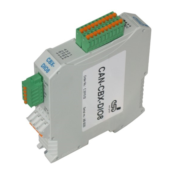
CAN-CBX-DIO8
Compact I/O-Module
with InRailBus
Manual
to Product C.3010.02
CAN-CBX-DIO8
Seite 1 von 123
Manual • Doc.-No.: C.3010.21 / Rev. 3.1
esd electronic system design gmbh
Vahrenwalder Str. 207 • 30165 Hannover • Germany
http://www.esd.eu
Phone: +49 (0) 511 3 72 98-0 • Fax: +49 (0) 511 3 72 98-68
Advertisement
Table of Contents

Subscribe to Our Youtube Channel
Related Manuals for ESD CAN-CBX-DIO8


Summary of Contents for ESD CAN-CBX-DIO8
- Page 1 CAN-CBX-DIO8 Seite 1 von 123 Manual • Doc.-No.: C.3010.21 / Rev. 3.1 esd electronic system design gmbh Vahrenwalder Str. 207 • 30165 Hannover • Germany http://www.esd.eu Phone: +49 (0) 511 3 72 98-0 • Fax: +49 (0) 511 3 72 98-68...
- Page 2 The information in this document has been carefully checked and is believed to be entirely reliable. esd makes no warranty of any kind with regard to the material in this document, and assumes no responsibility for any errors that may appear in this document. In particular descriptions and technical data specified in this document may not be constituted to be guaranteed product features in any legal sense.
- Page 3 Description of object revised 8.9.12 Description of object revised Declaration of Conformity updated Phoenix Contact order number of TBUS-connectors inserted in esd order information Technical details are subject to change without further notice. CAN-CBX-DIO8 Seite 3 von 123 Manual • Doc.-No.: C.3010.21 / Rev. 3.1...
- Page 4 This NOTICE statement contains the general mandatory sign and gives information that must be heeded and complied with for a safe use. INFORMATION INFORMATION Notes to point out something important or useful. Seite 4 von 123 CAN-CBX-DIO8 Manual • Doc.-No.: C.3010.21 / Rev. 3.1...
- Page 5 The installation and commissioning of the product may only be carried out by qualified personal, which is authorized to put devices, systems and electric circuits into operation according to the applicable national standards of safety engineering. CAN-CBX-DIO8 Seite 5 von 123 Manual • Doc.-No.: C.3010.21 / Rev. 3.1...
- Page 6 The intended use of the CAN-CBX module is the operation as a CANopen-Slave with digital in- and outputs. The esd guarantee does not cover damages which result from improper use, usage not in accordance with regulations or disregard of safety instructions and warnings.
-
Page 7: Table Of Contents
6.2.2 Cabling ......37 CAN-CBX-DIO8 Seite 7 von 123 Manual • Doc.-No.: C.3010.21 / Rev. 3.1... - Page 8 7.6 Support by esd ........
- Page 9 11. Order Information ............123 CAN-CBX-DIO8 Seite 9 von 123 Manual •...
-
Page 10: Overview
EEPROM. The eight digital in-/outputs can be individually set as outputs or inputs. The CAN-CBX-DIO8 features the possibility to connect the power supply and the CAN bus signals via the InRailBus connector (TBUS-connector) integrated in the mounting rail. Individual modules can then be removed without interrupting the bus signals. -
Page 11: Quick Start
Mount the CAN-CBX-module and connect the interfaces (power supply voltage, CAN, digital in/outputs). Please note that the CAN bus has to be terminated at both ends! esd offers special T-connectors and termination connectors. Additionally the CAN_GND signal has to be connected to earth at exactly one point in the CAN network. - Page 12 8 Byte 0...8 byte user data Set digital outputs Receive data Digital Input -> CAN CAN-Identifier Data + Node-ID 8 Byte 0...8 byte user data Set digital inputs Seite 12 von 123 CAN-CBX-DIO8 Manual • Doc.-No.: C.3010.21 / Rev. 3.1...
-
Page 13: Hardware Installation
Hardware Installation 3. Hardware Installation 3.1 Connecting Diagram Figure 2: Connections of the CAN-CBX-DIO8 module NOTICE Read chapter “Quick Start” on page 11, before you start with the installation of the hardware! INFORMATION Refer to page 34 for information on conductor connection and conductor cross section. -
Page 14: Front Panel View
3.2 Front Panel View Figure 3: Position of the LEDs and connector in the front panel The CAN-CBX-DIO8 module is equipped with 4 status LEDs and 8 LEDs for the I/O-channels. INFORMATION Refer to page 34 for information on conductor connection and conductor cross section. -
Page 15: Indicator States
The LED automatically turns off if 2 flashes Nodeguard/Heartbeat-messages are received again. The schematic diagram is not part of this manual. Table 3: Indicator states of the red CAN Error-LED CAN-CBX-DIO8 Seite 15 von 123 Manual • Doc.-No.: C.3010.21 / Rev. 3.1... -
Page 16: Operation Of The Canopen-Status Led
- indicator state lasts until the module resets or an error occurs at the outputs The schematic diagram is not part of this manual. Table 5: Indicator state of the Error-LED Seite 16 von 123 CAN-CBX-DIO8 Manual • Doc.-No.: C.3010.21 / Rev. 3.1... -
Page 17: Operation Of The Vio-Led
The coding switches for the node-ID are set to an invalid ID-value, when - CANopen-Status LED: 3 flashes switching on. The firmware application will be stopped. Table 7: Special Indicator States CAN-CBX-DIO8 Seite 17 von 123 Manual • Doc.-No.: C.3010.21 / Rev. 3.1... -
Page 18: I/O-Led 1-8
‘off’ input voltage level is higher than the upper switching threshold, or output state is ‘on’ Table 9: State of channels IO1...IO8 Seite 18 von 123 CAN-CBX-DIO8 Manual • Doc.-No.: C.3010.21 / Rev. 3.1... -
Page 19: Coding Switch
Setting the address range of the coding switches to values higher than 7F causes error messages, the red CAN-Error LED is on. If the coding switches are set to 00 , the CAN-CBX-module changes into Bootloader mode. CAN-CBX-DIO8 Seite 19 von 123 Manual • Doc.-No.: C.3010.21 / Rev. 3.1... -
Page 20: Setting The Baud Rate
83 3 . from firmware version 1.02 on Table 10: Index of the baud rate 3.3.3 Assignment of the Coding-Switch Labelling to the Name in the Schematic Diagram Labelling on the Name in Schematic Diagram * CAN-CBX-DIO8 Baud SW301 SW300 High SW302 The schematic diagram is not part of this manual. -
Page 21: Installation Of The Module Using Inrailbus Connector
Swivel the CAN-CBX module onto the mounting rail in pressing the module downwards according to the arrow as shown in figure 6. The housing is mechanically guided by the DIN rail bus connector. CAN-CBX-DIO8 Seite 21 von 123 Manual • Doc.-No.: C.3010.21 / Rev. 3.1... -
Page 22: Connecting Power Supply And Can-Signals To Cbx-Inrailbus
Plug the terminal plug into the socket on the right of the mounting-rail bus connector of the InRailBus, as described in Fig. 8. Then connect the CAN interface and the power supply voltage via the terminal plug. Seite 22 von 123 CAN-CBX-DIO8 Manual • Doc.-No.: C.3010.21 / Rev. 3.1... -
Page 23: Connection Of The Power Supply Voltage
Please note, that the impedance of the connection has to be kept low. The functional earth contact of the module does not ensure electrical safety. CAN-CBX-DIO8 Seite 23 von 123 Manual • Doc.-No.: C.3010.21 / Rev. 3.1... -
Page 24: Connection Of Can
Now the module is detached from the bottom edge of the mounting rail and can be removed. INFORMATION It is possible to remove individual devices from the CBX station without interrupting the InRailBus connection, because the contact chain will not be disrupted. Seite 24 von 123 CAN-CBX-DIO8 Manual • Doc.-No.: C.3010.21 / Rev. 3.1... -
Page 25: Technical Data
Phoenix “MEMAX” plastic housing for carrier rail mounting NS35/7,5 Housing DIN EN 60715 width: 22.5 mm, height: 99 mm, depth: 114.5 mm Dimensions (without connectors) Weight approx. 125 g Table 10: General data of the module CAN-CBX-DIO8 Seite 25 von 123 Manual • Doc.-No.: C.3010.21 / Rev. 3.1... -
Page 26: Cpu Unit
ISO 11898-2, transfer rate Physical layer CAN programmable from 10 Kbit/s up to 1 Mbit/s Bus termination has to be set externally if required Table 12: CAN interface data Seite 26 von 123 CAN-CBX-DIO8 Manual • Doc.-No.: C.3010.21 / Rev. 3.1... -
Page 27: Digital In-/Outputs
INOn 30 V INMax Table 13: Data of digital in/outputs 4.5 Software Support ® ® The firmware of the module supports the CiA CANopen Specification CiA 301 [1]. CAN-CBX-DIO8 Seite 27 von 123 Manual • Doc.-No.: C.3010.21 / Rev. 3.1... -
Page 28: Connector Pin Assignment
INFORMATION The pins 1 and 4 are connected internally. The pins 2 and 3 are connected internally Signal Description: P24... power supply voltage +24 V M24... reference potential Seite 28 von 123 CAN-CBX-DIO8 Manual • Doc.-No.: C.3010.21 / Rev. 3.1... -
Page 29: Can
The CAN interface can be connected via the CAN connector or optionally via the InRailBus. Use the mounting-rail bus connector of the CBX-InRailBus (CAN-CBX-TBUS), see order information (page 123). CAN-CBX-DIO8 Seite 29 von 123 Manual • Doc.-No.: C.3010.21 / Rev. 3.1... -
Page 30: Can Connector (X600)
STF-3,81 with spring-cage-connection) to 9-pin DSUB: T he 9-pin DSUB connector is assigned according to CiA 102 Figure 12: Assignment of the 9-pin DSUB-connector according to CiA DS 102. Seite 30 von 123 CAN-CBX-DIO8 Manual • Doc.-No.: C.3010.21 / Rev. 3.1... -
Page 31: Can And Power Supply Voltage Via Inrailbus Connector X101
CAN signals CAN_GND ... reference potential of the local CAN-Physical layers P24... power supply voltage +24 V M24... reference potential FE... functional earth contact (EMC)(connected to mounting rail potential) CAN-CBX-DIO8 Seite 31 von 123 Manual • Doc.-No.: C.3010.21 / Rev. 3.1... -
Page 32: Digital In/Outputs X400
Connector Pin Assignment 5.4 Digital In/Outputs X400 5.4.1 Digital Inputs Figure 13: Digital input circuit (Example: IO1) 5.4.2 Digital Outputs Figure 14: Digital output circuit (Example: IO1) Seite 32 von 123 CAN-CBX-DIO8 Manual • Doc.-No.: C.3010.21 / Rev. 3.1... -
Page 33: Connector Assignment Digital In-/Outputs (X400)
1 and 11. These pins are connected to each other on the PCB. NOTICE To ensure EU Conformity a cable with a maximum wire length of 30 m has to be used for the digital inputs and digital outputs. CAN-CBX-DIO8 Seite 33 von 123 Manual • Doc.-No.: C.3010.21 / Rev. 3.1... -
Page 34: Conductor Connection/Conductor Cross Sections
2 conductors with same cross section, stranded, 1 mm² n.a. n.a. TWIN ferrules with plastic sleeve, max. Minimum AWG according to UL/CUL Maximum AWG according to UL/CUL n.a..not allowed Seite 34 von 123 CAN-CBX-DIO8 Manual • Doc.-No.: C.3010.21 / Rev. 3.1... -
Page 35: Correct Wiring Of Electrically Isolated Can Networks
Therefore the practical maximum number of nodes, bus length and stub length are typically much lower. esd has concentrated her recommendations concerning CAN wiring on the specifications of the ISO 11898-2. Thus this wiring hints forgoes to describe the special features of the derived standards CANopen, ARINC825, DeviceNet and NMEA2000. -
Page 36: Light Industrial Environment (Single Twisted Pair Cable)
6.2.1 General Rules NOTICE esd grants the EU Conformity of the product, if the CAN wiring is carried out with at least single shielded single twisted pair cables that match the requirements of ISO 118982-2. Single shielded double twisted pair cable wiring as described in chapter 6.3 ensures the EU Conformity as well. -
Page 37: Cabling
CAN termination plug. 9-pin DSUB-termination connectors with integrated termination resistor and male and female contacts are available from esd (order no. C.1303.01). DSUB termination connectors with male contacts (order no. C.1302.01) or female contacts (order no. C.1301.01) and additional functional earth contact are available, if CAN termination and grounding of CAN_GND is required. -
Page 38: Heavy Industrial Environment (Double Twisted Pair Cable)
Select a working combination of bit rate and cable length. Keep away CAN cables from disturbing sources. If this cannot be avoided, double shielded cables are recommended. Fig. 17: CAN wiring for heavy industrial environment Seite 38 von 123 CAN-CBX-DIO8 Manual • Doc.-No.: C.3010.21 / Rev. 3.1... -
Page 39: Device Cabling
DSUB9-connector from ERNI (ERBIC CAN BUS MAX, order no.:154039). The usage of esd’s T-connector type C.1311.03 is not recommended for single shielded double twisted pair cables because the shield potential of the conductive DSUB housing is not looped through this T-connector type. -
Page 40: Electrical Grounding
Table 14: Recommended cable lengths at typical bit rates (with esd-CAN interfaces) Optical couplers are delaying the CAN signals. esd modules typically reach a wire length of 37 m at 1 Mbit/s within a proper terminated CAN network without impedance disturbances like... -
Page 41: Examples For Can Cables
> 0.3 m. 6.6 Examples for CAN Cables esd recommends the following two-wire and four-wire cable types for CAN network design. These cable types are used by esd for ready-made CAN cables, too. 6.6.1 Cable for Light Industrial Environment Applications (Two-Wire) -
Page 42: Can Troubleshooting Guide
- there are no open circuits in CAN_H or CAN_L wiring - your bus system has two terminating resistors (one at each end) and that they are 120 each. Seite 42 von 123 CAN-CBX-DIO8 Manual • Doc.-No.: C.3010.21 / Rev. 3.1... -
Page 43: Electrical Grounding
(see figure at previous page). Measure the DC voltage between CAN_L and CAN_ GND (see figure at previous page). Normally the voltage should be between 2.0 V and 3.0 V. CAN-CBX-DIO8 Seite 43 von 123 Manual • Doc.-No.: C.3010.21 / Rev. 3.1... -
Page 44: Can Transceiver Resistance Test
(>> 200%). Figure 21: Simplified diagram of a CAN node 7.6 Support by esd If you have executed the fault diagnostic steps of this troubleshooting guide and you even can not find a solution for your problem our support department will be able to assist. -
Page 45: Canopen Firmware
PDOs (Process Data Objects) PDOs are used to transmit process data. In the ‘Receive’-PDO (RxPDO) process data is received by the CAN-CBX-DIO8 module. In the ‘Transmit’-PDO (TxPDO) the CAN-CBX-DIO8 module transmits data to the CANopen network. SDOs (Service Data Objects) SDOs are used to transmit module internal configuration- and parameter data. -
Page 46: Nmt Boot-Up
CANopen-Firmware 8.2 NMT Boot-up The CAN-CBX-DIO8 module can be initialized with the ‘Minimum Capability Device’ boot-up as described in [1]. Usually a telegram to switch from Pre-Operational status to Operational status after boot-up is sufficient. For this the 2-byte telegram ‘01 ’, ‘00... -
Page 47: Communication Parameters Of The Pdos
= 35 : Write Request with 32-bit data, i.e. a parameter is to be set The CAN-CBX-module responds to every received telegram with a response telegram. This can CAN-CBX-DIO8 Seite 47 von 123 Manual • Doc.-No.: C.3010.21 / Rev. 3.1... - Page 48 The least significant byte is always in ‘Data 1’. With 16-bit values the most significant byte (bits 8...15) is always in ‘Data 2’, and with 32-bit values the MSB (bits 24...31) is always in ‘Data 4’. Seite 48 von 123 CAN-CBX-DIO8 Manual • Doc.-No.: C.3010.21 / Rev. 3.1...
-
Page 49: Non-Volatile Storage Of Parameters To Eeprom
, sub-index 1 is not set, i.e the CAN-CBM-module does not save the configuration automatically. The storage must be initiated by writing the character string ‘save’ (73 , order from CAN telegram) to object 1010 , sub-index 1 CAN-CBX-DIO8 Seite 49 von 123 Manual • Doc.-No.: C.3010.21 / Rev. 3.1... -
Page 50: Overview Of Used Canopen Identifiers
Network management SYNC Sync to all, (configurable via object 1005 Emergency Message + Node-ID configurable via object 1014 Client-PDO + Node-ID PDO from CAN-CBX-DIO8 (object 1800 Server-PDO + Node-ID PDO to CAN-CBX-DIO8 (object 1400 Client-SDO + Node-ID SDO from CAN-CBX-DIO8 Server-SDO... -
Page 51: Pdo Assignment
CAN-CBX-DIO8 + Node-ID 1 byte Setting of the outputs (Receive-PDO) from CAN-CBX-DIO8 + Node-ID 1 byte Request the state of the inputs (Transmit-PDO) RPDO1 (-> CAN-CBX-DIO8) CAN identifier: 200 + Node-ID Byte Write_ Output_ Parameter DO8-DO1 Parameter description: Name Description... -
Page 52: Setting And Reading Of The Out/Inputs
• event controlled, asynchronous: The transmission is initiated if the state of selected inputs has changed (PDO-transmission type 254, 255). 8.7.2 Digital Outputs The digital outputs are set, as soon as an output setting object is received by the CAN-CBX-DIO8 (e.g. object 6200 via Rx-PDO). -
Page 53: Communication Profile Area
This parameter can be read or written. Value range value range of the parameter Default value default setting of the parameter Name/Description name and short description of the parameter CAN-CBX-DIO8 Seite 53 von 123 Manual • Doc.-No.: C.3010.21 / Rev. 3.1... -
Page 54: Implemented Canopen-Objects
1005 COB-ID-Sync unsigned 32 default: 80 1006 Communication Cycle Period unsigned32 default: 00 1008 Manufacturer Device Name visible string “CAN-CBX-DIO8” Manufacturer Hardware x.yy 1009 visible string (depending on version) Version x.yy 100A Manufacturer Software Version visible string (depending on version) - Page 55 Data type index mode properties (max.) default: 2 (autostart 1F80 NMT startup unsigned 32 disabled) Self starting nodes timing 1F91 unsigned 16 default: 64 (= 100 ms) parameters CAN-CBX-DIO8 Seite 55 von 123 Manual • Doc.-No.: C.3010.21 / Rev. 3.1...
-
Page 56: Device Type
CBX-DIO8 module with the module no. 3 (Node-ID=3 DATA Read Index=1000 Sub- Request index The CAN-CBX-DIO8 module no. 3 responds to the master by means of read response on identifier ‘583 ’ (580 + Node-ID) with the value of the device type: DATA Read Index=1000 Sub-index dig. -
Page 57: Error Register
Implemented CANopen Objects 8.9.2 Error Register (1001 This object is an error register for the CAN-CBX-DIO8. INDEX 1001 Name error register Data type unsigned 8 Access mode Default value The following bits of the error register are being supported at present:... -
Page 58: Pre-Defined Error Field (1003 )
- if no_of_errors_in_list 0, the error register (Object 1001 ) is set error-code x The 32-bit long error code consists of the CANopen-Emergency-Error-Code described in DS 301, Table 21 and the error code defined by esd (Manufacturer-Specific Error Field). Seite 58 von 123 CAN-CBX-DIO8... - Page 59 (no load detected at least at one output) 2320 - Output Error: short circuit at outputs (at least one output shorted to GND) Emergency Frame The data of the emergency frame transmitted by the CAN-CBX-DIO8 have the following structure: Byte: error- no_of_errors_ emergency-error-code...
-
Page 60: Cob-Id Sync Message (1005 )
1: Device generates SYNC message always 0 (11-bit ID) 28...11 always 0 (29-bit IDs are not supported) 10...0 (LSB) Bit 0...10 of the SYNC-COB-ID The identifier can take values between 0...7FF Seite 60 von 123 CAN-CBX-DIO8 Manual • Doc.-No.: C.3010.21 / Rev. 3.1... -
Page 61: Communication Cycle Period 1006
Access mode Default value Value range of communication cycle period: Value Meaning No transmission of SYNC messages 1 ... FFFF FFFF Cycle time of the SYNC frame in microseconds CAN-CBX-DIO8 Seite 61 von 123 Manual • Doc.-No.: C.3010.21 / Rev. 3.1... -
Page 62: Manufacturer's Device Name (1008 )
8.9.6 Manufacturer’s Device Name (1008 INDEX 1008 Name manufacturer’s device name Data type visible string Default value string: ‘CAN-CBX-DIO8’ For detailed description of the SDOn Uploads, please refer to CiA [1]. Seite 62 von 123 CAN-CBX-DIO8 Manual • Doc.-No.: C.3010.21 / Rev. 3.1... -
Page 63: Manufacturer's Hardware Version (1009 )
Reading the software version is similar to reading the manufacturer device name via the domain upload protocol. Please refer to [1] for a detailed description of the upload. CAN-CBX-DIO8 Seite 63 von 123 Manual • Doc.-No.: C.3010.21 / Rev. 3.1... -
Page 64: Guard Time
Implemented CANopen Objects 8.9.9 Guard Time (100C ) und Life Time Factor (100D The CAN-CBX-DIO8 module supports the node guarding or alternatively the heartbeat function (see page 74). INFORMATION By the recommendation of the CiA, the heartbeat-function shall be used preferentially. -
Page 65: Node Guarding Identifier (100E )
31 (MSB) reserved 29...11 always 0, because 29-bit IDs are not supported 10...0 (LSB) bit 0...10 of the Node Guarding Identifier The identifier can take values between 1...7FF CAN-CBX-DIO8 Seite 65 von 123 Manual • Doc.-No.: C.3010.21 / Rev. 3.1... -
Page 66: Store Parameters (1010 )
(objects 2000 ... 5FFF , if available), which have a read/write (rw) right of access (here e.g. 2xxx The storage mode is shown in the content of this object: Seite 66 von 123 CAN-CBX-DIO8 Manual • Doc.-No.: C.3010.21 / Rev. 3.1... - Page 67 CAN-CBX module does not save the parameters on command CAN-CBX module saves the parameters on command Autonomous saving means that the CAN-CBX module stores the storable parameters non-volatile and without a user request. CAN-CBX-DIO8 Seite 67 von 123 Manual • Doc.-No.: C.3010.21 / Rev. 3.1...
-
Page 68: Restore Default Parameters (1011 )
(objekts 6000 ... 9FFF , if available, here e.g. 6xxx restore_manufacturer_parameter loads all manufacturer default parameters of those objects (objects 2000 ... 5FFF , if available, here e.g. 2xxx Seite 68 von 123 CAN-CBX-DIO8 Manual • Doc.-No.: C.3010.21 / Rev. 3.1... - Page 69 On read access to the appropriate sub-index, the CANopen device provides information about its default parameter restoring capability with the following format: Bit: Content: reserved Value Description the CAN-CBX-module does not restore default parameters the CAN-CBX-module restores the default parameters CAN-CBX-DIO8 Seite 69 von 123 Manual • Doc.-No.: C.3010.21 / Rev. 3.1...
-
Page 70: Cob_Id Emergency Object (1014 )
(always 0) always 0 (11-bit ID) 28...11 always 0 (29-bit IDs are not supported) 10...0 (LSB) bits 0...10 of COB-ID The identifier can take values between 0...7FF Seite 70 von 123 CAN-CBX-DIO8 Manual • Doc.-No.: C.3010.21 / Rev. 3.1... -
Page 71: Inhibit Time Emcy (1015 )
Value range 0-FFFF Default value The Inhibit Time for the EMCY message can be adjusted via this entry. The time is determined as a multiple of 100 s. CAN-CBX-DIO8 Seite 71 von 123 Manual • Doc.-No.: C.3010.21 / Rev. 3.1... -
Page 72: Consumer Heartbeat Time (1016 )
It has to be received within the heartbeat time stored on the heartbeat consumer, otherwise a heartbeat event is triggered on the heartbeat-consumer module. A heartbeat event generates a heartbeat error on the CAN-CBX-DIO8 module. Each module can act as a heartbeat producer and a heartbeat consumer. The CAN-CBX-module can represent at most one heartbeat consumer . - Page 73 Example: consumer-heartbeat_time = 0031 03E8 => Node-ID = 31 = 49 => heartbeat time = 3E8 = 1000 => 1 s CAN-CBX-DIO8 Seite 73 von 123 Manual • Doc.-No.: C.3010.21 / Rev. 3.1...
-
Page 74: Producer Heartbeat Time (1017 )
Default value 0 ms The producer heartbeat time defines the cycle time with which the CAN-CBX-DIO8 module transmits a heartbeat-frame to the node-guarding ID. The heartbeat function is described on page 72. If the value of the producer heartbeat time is higher than ‘0’, it is active and stops the Node-/ Life- Guarding (see page 64). -
Page 75: Identity Object (1018 )
0...FFFF FFFF unsigned32 Parameter Description: vendor_id This variable contains the esd-vendor-ID. This is always 00000017 product_code Here the esd-article number of the product is stored. Example: Value ‘2301 0002 ’ corresponds to article number ‘C.3010.02’. The nibbles of the long words have the following meaning: product_code = abcd efgh 1... - Page 76 If the value ‘C1C2 0105 ’ is being read, this corresponds to the hardware- serial number code ‘AB 0105’. This value has to correspond to the serial number of the module. Seite 76 von 123 CAN-CBX-DIO8 Manual • Doc.-No.: C.3010.21 / Rev. 3.1...
-
Page 77: Synchronous Counter Overflow Value 1019
The SYNC message shall be transmitted as a CAN message of data length ‘1’. The 2...240 first data byte of the SYNC message contains the value of the SYNC-counter. 241...255 reserved CAN-CBX-DIO8 Seite 77 von 123 Manual • Doc.-No.: C.3010.21 / Rev. 3.1... -
Page 78: Verify Configuration (1020 )
Date of the last configuration of the module. The value is defined in number of days since the 01.01.1984. configuration_time Time in ms since midnight at the day of the last configuration. Seite 78 von 123 CAN-CBX-DIO8 Manual • Doc.-No.: C.3010.21 / Rev. 3.1... -
Page 79: Error Behaviour Object (1029 )
VIO is lower than the value defined in object 2300 , sub-index 2. VIO_high_warning output driver power supply error: VIO is higher than the value defined in object 2300 , sub-index 3. CAN-CBX-DIO8 Seite 79 von 123 Manual • Doc.-No.: C.3010.21 / Rev. 3.1... - Page 80 Implemented CANopen Objects The module can enter the following states if an error occurs. Parameter Module states value pre-operational (only if the current state is operational) no state change stopped Seite 80 von 123 CAN-CBX-DIO8 Manual • Doc.-No.: C.3010.21 / Rev. 3.1...
-
Page 81: Nmt Startup (1F80 )
Further features of the parameters NMT startup are currently not supported. The value range of the oject is described in the following table: Value Meaning Auto startup disabled (default) Auto startup enabled all other values reserved CAN-CBX-DIO8 Seite 81 von 123 Manual • Doc.-No.: C.3010.21 / Rev. 3.1... -
Page 82: Self Starting Nodes Timing Parameters (1F91 )
Sub-index 1 of this object contains the timeout in [ms] between the change from “preoperational” > “operational”. In default it is 100 ms. The sub-indices 2 and 3 of this object are not supported. Seite 82 von 123 CAN-CBX-DIO8 Manual • Doc.-No.: C.3010.21 / Rev. 3.1... -
Page 83: Receive Pdo Communication Parameter 1400
Default Data type mode no_of_entries unsigned 8 COB_ID used by 1... unsigned 32 1400 PDO1 8000 07FF Node-ID transmission type 0...FF unsigned 8 All transmission types are supported. CAN-CBX-DIO8 Seite 83 von 123 Manual • Doc.-No.: C.3010.21 / Rev. 3.1... -
Page 84: Receive Pdo Mapping Parameter 1600
In general there is the possibility to access several CAN-CBX-DIO8 modules synchronously. The CAN-CBX-DIO8 modules can be configured so that up to 8 CAN-CBX-DIO8 modules can be addressed with a single CAN frame simultaneously. Therefore all 64 digital outputs can be set simultaneously. - Page 85 Subindices from 01 to 08 contain the information of the mapped application objects. The entry describes the content of the PDO by their index, subindex and length. For the CAN-CBX-DIO8 module the value 6200 0108 (index 6200 , subindex 01...
- Page 86 Module 3 Objekt 1600 Objekt 1600 Objekt 1600 62000108 00050008 00050008 00050008 62000108 00050008 00050008 00050008 62000108 Figure 22: Example for the Rx-PDO mapping with three CAN-CBX-DIO8 modules Seite 86 von 123 CAN-CBX-DIO8 Manual • Doc.-No.: C.3010.21 / Rev. 3.1...
-
Page 87: Object Transmit Pdo1 Communication Parameter 1800
The transmission types 0, 1...240, 252, 253 and 255 are supported. Per default the highest bit of the parameter COB-ID used by_PDO1 is not set: 0000 0000 +180 +Node-ID Per default this object is valid. CAN-CBX-DIO8 Seite 87 von 123 Manual • Doc.-No.: C.3010.21 / Rev. 3.1... -
Page 88: Object Transmit Pdo2 Communication Parameter 1801
The transmission types 0, 1...240, 252, 253 and 255 are supported. Per default the highest bit of the parameter COB-ID used by_PDO2 is set: 8000 0000 +280 +Node-ID Per default this object is not valid. Seite 88 von 123 CAN-CBX-DIO8 Manual • Doc.-No.: C.3010.21 / Rev. 3.1... -
Page 89: Transmit Pdo1 Mapping Parameter 1A00
The Transmit PDO1-Mapping parameters can not be modified, if the PDO1 is valid. To change the value of the parameter object_to_be_mapped the value of the parameter COB-ID_used_by_PDO1 in object 1800 (page 87) has to be set to not valid. CAN-CBX-DIO8 Seite 89 von 123 Manual • Doc.-No.: C.3010.21 / Rev. 3.1... -
Page 90: Transmit Pdo2 Mapping Parameter 1A01
If the PDO2 is not valid the Transmit PDO2-Mapping parameters can be modified. To activate the PDO2-Mapping the value of the parameter COB-ID_used_by_PDO2 in object 1801 (page 88) has to be set to valid. Seite 90 von 123 CAN-CBX-DIO8 Manual • Doc.-No.: C.3010.21 / Rev. 3.1... - Page 91 PDO2 unsigned 8 object_to_be_mapped_1 0005 00 08 unsigned 8 object_to_be_mapped_2 6000 01 08 unsigned 8 1A01 object_to_be_mapped_3 2403 05 20 unsigned 32 object_to_be_mapped_4 2402 01 10 unsigned 16 CAN-CBX-DIO8 Seite 91 von 123 Manual • Doc.-No.: C.3010.21 / Rev. 3.1...
-
Page 92: Device Profile Area
8 6200 Write Output 8-bit unsigned 8 6202 Change Polarity Output unsigned 8 6206 Error Mode Output 8-bit unsigned 8 6207 Error Value Output 8-bit unsigned 8 Seite 92 von 123 CAN-CBX-DIO8 Manual • Doc.-No.: C.3010.21 / Rev. 3.1... -
Page 93: Interrelation Of The Implemented Objects Of The Digital Inputs
Device Profile Area 8.10.2 Interrelation of the Implemented Objects of the Digital Inputs ≥ Fig. 23: Overview of the objects for the digital inputs CAN-CBX-DIO8 Seite 93 von 123 Manual • Doc.-No.: C.3010.21 / Rev. 3.1... -
Page 94: Interrelation Of The Implemented Objects Of The Digital Outputs
Device Profile Area 8.10.3 Interrelation of the Implemented Objects of the Digital Outputs Fig. 24: Overview of the objects for the digital outputs Seite 94 von 123 CAN-CBX-DIO8 Manual • Doc.-No.: C.3010.21 / Rev. 3.1... -
Page 95: Read Input 8-Bit (6000 )
An input bit is read as ‘1’, if the corresponding input is active, i.e. voltage is ‘on’ (if the according bit in object 6002 ‘Polarity Input 8-Bit’ is set to ‘0’). CAN-CBX-DIO8 Seite 95 von 123 Manual • Doc.-No.: C.3010.21 / Rev. 3.1... -
Page 96: Polarity Input 8-Bit (6002 )
_entries unsigned 8 6002 polarity_input_DI8-DI1 0...FF unsigned 8 Assignment of the parameter polarity_input_DI8-DI1: Index: 6002 , Sub-index: 1 Bit: Input: Bit value DIx Input inverted not inverted Seite 96 von 123 CAN-CBX-DIO8 Manual • Doc.-No.: C.3010.21 / Rev. 3.1... -
Page 97: Filter Constant Input 8-Bit (6003 )
6003 filter constant _DI8-DI1 0...FF unsigned 8 Assignment of the parameter filter constant_DI8-DI1: Index: 6003 , Sub-index: 1 Bit: Input: Bit value DIx Input filter enabled filter disabled CAN-CBX-DIO8 Seite 97 von 123 Manual • Doc.-No.: C.3010.21 / Rev. 3.1... -
Page 98: Global Interrupt Enable Digital (6005 )
Index Description Default Data type index [Boolean] mode Global Interrupt Enable-Bit = false : interrupts disabled True, False boolean 6005 Global Interrupt Enable-Bit = true : interrupts enabled Seite 98 von 123 CAN-CBX-DIO8 Manual • Doc.-No.: C.3010.21 / Rev. 3.1... -
Page 99: Interrupt Mask Any Change 8-Bit (6006 )
, Sub-index: 1 Bit: Input: This object determines, which input port lines shall activate an interrupt by rising or falling edge detection. Bit-value DIx Interrupt-enable interrupt disabled interrupt enabled CAN-CBX-DIO8 Seite 99 von 123 Manual • Doc.-No.: C.3010.21 / Rev. 3.1... -
Page 100: Interrupt Mask Low To High 8-Bit (6007 )
Index: 6007 , Sub-index: 1 Bit: Input: For activated IRQ an interrupt is generated by rising edge detection of the input signal. Bit-value DIx Interrupt-enable interrupt disabled interrupt enabled Seite 100 von 123 CAN-CBX-DIO8 Manual • Doc.-No.: C.3010.21 / Rev. 3.1... -
Page 101: Interrupt Mask High To Low 8-Bit (6008 )
, Sub-index: 1 Bit: Input: For activated IRQ an interrupt is generated by falling edge detection of the input signal. Bit Value DIx Interrupt enable interrupt disabled interrupt enabled CAN-CBX-DIO8 Seite 101 von 123 Manual • Doc.-No.: C.3010.21 / Rev. 3.1... -
Page 102: Write Output 8-Bit (6200 )
Assignment of the variable write_output_DO8-DO1: Index: 6200 , Sub-index: 1 Bit: Output: If an output bit is set to ‘1’, the corresponding output is activated, i.e. the output voltage is ‘on’. Seite 102 von 123 CAN-CBX-DIO8 Manual • Doc.-No.: C.3010.21 / Rev. 3.1... -
Page 103: Change Polarity Output 8-Bit (6202 )
8 Assignment of the parameter change_polarity_output_DO8-DO1: The parameter determines which digital output can be inverted. Bit: Contents: Setting an output bit to ‘1’ inverts the corresponding output. CAN-CBX-DIO8 Seite 103 von 123 Manual • Doc.-No.: C.3010.21 / Rev. 3.1... -
Page 104: Error Mode Output 8-Bit (6206 )
Assignment of the parameter error_mode_output_DO8-DO1: Bit: Contents: Value Meaning Output shall take the pre-defined value specified in object 6207 Output shall be kept unchanged if an error occurs. Seite 104 von 123 CAN-CBX-DIO8 Manual • Doc.-No.: C.3010.21 / Rev. 3.1... -
Page 105: Error Value Output 8-Bit (6207 )
Output shall be set to ‘1’ (enabled) in case of fault, if object 6206 is enabled. Output shall be set to ‘0’ (disabled) in case of fault, if object 6206 is enabled. CAN-CBX-DIO8 Seite 105 von 123 Manual • Doc.-No.: C.3010.21 / Rev. 3.1... -
Page 106: Manufacturer Specific Profile Area
2310 Sample Configuration unsigned 16 2400 Counter Enable unsigned 8 2401 Counter Preload unsigned 32 2402 Counter Value 16- Bit unsigned 16 2403 Counter Value 32-Bit unsigned 32 Seite 106 von 123 CAN-CBX-DIO8 Manual • Doc.-No.: C.3010.21 / Rev. 3.1... -
Page 107: Output Errors 8-Bit (2210 )
Output: DIO8 DIO7 DIO6 DIO5 DIO4 DIO3 DIO2 DIO1 The output bits are set to ‘1’, in case of error at the corresponding output. CAN-CBX-DIO8 Seite 107 von 123 Manual • Doc.-No.: C.3010.21 / Rev. 3.1... -
Page 108: Output Error Produces Emergency 8-Bit (2220 )
INFORMATION The object Output Error Mask Bit 1 to 8 has no effect on the current error state that is returned in the object Output Errors 8-Bit (2210 Seite 108 von 123 CAN-CBX-DIO8 Manual • Doc.-No.: C.3010.21 / Rev. 3.1... -
Page 109: I/O Direction Mask 8-Bit (2250 )
Assignment of the parameter I/O_direction_mask_DIO8-DIO1: Index: 2250 , Sub-index: 1 Bit: Output: DIO8 DIO7 DIO6 DIO5 DIO4 DIO3 DIO2 DIO1 Value Meaning channel is used as output channel is used as input CAN-CBX-DIO8 Seite 109 von 123 Manual • Doc.-No.: C.3010.21 / Rev. 3.1... -
Page 110: Vio Voltage 16-Bit (2300 )
This variable defines the voltage limit that initiates an Emergency Message, if the value falls below. Example: = disable = 280 (value of the variable) = 28 V voltage, above this limit an Emergency Message is initiated Seite 110 von 123 CAN-CBX-DIO8 Manual • Doc.-No.: C.3010.21 / Rev. 3.1... -
Page 111: Sample Configuration (2310 )
Resulting sample rate sample_rate [ s] [Dec] current parameter value is not changed (old value will stay valid + SDO error message) 100 (default value) 100.5 65535 32767.5 CAN-CBX-DIO8 Seite 111 von 123 Manual • Doc.-No.: C.3010.21 / Rev. 3.1... -
Page 112: Function Of The Counter
If the counter function of an input is used, it is strongly recommended to disable the local interrupts via the Interrupt Mask-objects 6006 , 6007 and 6008 (reduces bus load of the CAN bus). Seite 112 von 123 CAN-CBX-DIO8 Manual • Doc.-No.: C.3010.21 / Rev. 3.1... - Page 113 The maximum attainable input clock rate results from the sample rate of the inputs (see object Sample Configuration 2310 Fig. 25: Interrelation of maximum count frequency and sample rate So the absolute maximum of the countable input frequency is 5 kHz. CAN-CBX-DIO8 Seite 113 von 123 Manual • Doc.-No.: C.3010.21 / Rev. 3.1...
-
Page 114: Counter Enable (2400 )
(object 6002 Assignment of the variable counter enable: Index: 2400 , Subindex: 0 Bit: counter8 counter7 counter6 counter5 counter4 counter3 counter2 counter1 Port: Value Description counter enabled counter disabled Seite 114 von 123 CAN-CBX-DIO8 Manual • Doc.-No.: C.3010.21 / Rev. 3.1... -
Page 115: Counter Preload (2401 )
In this object the initial values counter_preload_1...8 of the counters 1...8 are defined. Beginning from the initial value counter_preload_x the counter value is decremented by ‘1’, if a change occurs. CAN-CBX-DIO8 Seite 115 von 123 Manual • Doc.-No.: C.3010.21 / Rev. 3.1... -
Page 116: Counter Value 16-Bit (2402H)
The following table shows the position of the 16-bit counter value counter_value_x_16-bit in the 32-bit counter value counter_value_x_32-bit: Bit 31..Bit 0 counter_preload_x counter_value_x_32-bit Bit 31..Bit 16 Bit 15..Bit 0 counter_value_x_16-bit Seite 116 von 123 CAN-CBX-DIO8 Manual • Doc.-No.: C.3010.21 / Rev. 3.1... -
Page 117: Counter Value 32-Bit (2403H)
‘1’, if a change occurs (x = 1...8). An event is generated, if the value of the 32-bit counter results in ‘0’. If the value of counter_preload_x is set to ‘0000.0000’, the preload is 2 CAN-CBX-DIO8 Seite 117 von 123 Manual • Doc.-No.: C.3010.21 / Rev. 3.1... -
Page 118: Firmware Management Via Cia Dsp- 302-Objects
Faulty program update can result in deleting of the memory and loss of the firmware. The module then can not be operated further! INFORMATION esd offers the program CANfirmdown for a firmware update. Please, contact our support for this. In normal CiA 301 mode the objects 1F50 and 1F52 can not be accessed. -
Page 119: Download Control Via Object 1F51
0...2 unsigned 8 INFORMATION The value range of this object in the implementation for the CAN-CBX-DIO8 differs from the value range specified in CiA 302 [2]. For further information about object 1F51 and the firmware-update please refer to the standard [2]. -
Page 120: Download Control Via Object 1F52
-> 26.10.2001 application_software_time Time is the number of milliseconds since midnight of the day of the generation of the last application software. Example: 02A0 AB8E -> approx. 12:14 pm Seite 120 von 123 CAN-CBX-DIO8 Manual • Doc.-No.: C.3010.21 / Rev. 3.1... -
Page 121: References
PCB plug connector - FK-MCP 1,5/ 5-STF-3,81 - 1851261, downloaded 2013-10-09 [6] Phoenix Contact GmbH & Co. KG, Blomberg., Technical data is taken from the Phoenix Contact website: https://www.phoenixcontact.com/online/portal/de; PCB plug connector -FMC- 1,5/10-ST-3,5 - 1952348, downloaded 2013-10-09 CAN-CBX-DIO8 Seite 121 von 123 Manual • Doc.-No.: C.3010.21 / Rev. 3.1... -
Page 122: Declaration Of Conformity
10. Declaration of Conformity Seite 122 von 123 CAN-CBX-DIO8 Manual • Doc.-No.: C.3010.21 / Rev. 3.1... -
Page 123: Seite 8 Von
Table 15: Order information PDF Manuals Manuals are available in English and usually in German as well. For availability of English manuals see the following table. Please download the manuals as PDF documents from our esd website www.esd.eu for free.
Need help?
Do you have a question about the CAN-CBX-DIO8 and is the answer not in the manual?
Questions and answers