
Related Manuals for ESD CAN-CBM-REL4


Summary of Contents for ESD CAN-CBM-REL4
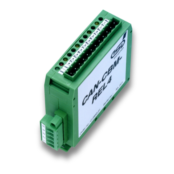
- Page 1 CAN-CBM-REL4 CAN Module with 4 Relay Outputs Hardware Manual CAN-CBM-REL4 Hardware Manual Rev. 1.2...
- Page 2 The changes in the document listed below affect changes in the hardware as well as changes in the description of the facts only. Chapter Changes versus previous version Change of LED signals Changes concerning manual configuration Description of pin assignment changed Technical details are subject to change without further notice. CAN-CBM-REL4 Hardware Manual Rev. 1.2...
- Page 3 gmbh.
-
Page 4: Table Of Contents
1.1 Description of the CAN-CBM-REL4 Module ........ - Page 5 This page is intentionally left blank. CAN-CBM-REL4 Hardware Manual Rev. 1.2...
-
Page 6: Overview
The individual channels are electrically insulated and therefore various voltages can be applied to the CAN-CBM-REL4 module simultaneously. The CAN-CBM-REL4 module operates with a local micro controller of C505C type, which has an integrated CAN controller. By means of two HEX rotary switches connected to the micro controller the CAN-CBM-REL4 module can be configured manually. - Page 7 This page is intentionally left blank. CAN-CBM-REL4 Hardware Manual Rev. 1.2...
-
Page 8: Case View And Led Description
The CAN connection, a 5-pin COMBICON connector (MSTBT2.5/5-5.08), is at the lower case side. The case can be locked onto carrier rails according to EN 50 022 (hat rail) by means of clips at the back of the case. CAN-CBM-REL4 Hardware Manual Rev. 1.2... -
Page 9: Front View With Led And Connector Description
Module Status LED (red) Module Power Supply 18V...30V +24V +24V Module Status LED (green) Module GND Designation: Ro... Root (COM - common) Pr... Process (N.O. - normally opened ) Br... Break (N.C. - normally closed) CAN-CBM-REL4 Hardware Manual Rev. 1.2... -
Page 10: Led Displays
RUN Status of the Description green CANopen RUN LED CAN module single flash STOPPED (200 ms on, 1 s off) blinking PRE-OPERATIONAL (200 ms on, 200 ms off) LED on OPERATIONAL Table 2.3.2: Display of the green LED CAN-CBM-REL4 Hardware Manual Rev. 1.2... - Page 11 Baud rate - configured CAN bit rate is not permitted (je 200 ms on, 200 ms off, 1 s pause) * these errors occurs only during configuration via coding switches Table 2.3.3: Display of red LED CAN-CBM-REL4 Hardware Manual Rev. 1.2...
-
Page 12: Configuration Via Rotary Switches
When the configuration has been finished, the module number is set via both rotary switches: Setting the module number 01-7Fh: CAN-CBM-REL4 module is started with the configuration presently stored in the EEPROM. The module number corresponds to the current position of the rotary switches when the module is switched on and is not to be changed during operation. -
Page 13: Position Of Rotary Switches
The rotary switches for the manual configuration and the setting of the module number are on the upper side of the case. Coding switch SW 110 (Low) Coding switch SW 111 (High) Coding switch SW110 (Low) Coding switch SW111 (High) +24V +24V Fig. 3.1: Case view CAN-CBM-REL4 Hardware Manual Rev. 1.2... -
Page 14: Manual Configuration Via Coding Switches
In order to load the default configuration the two rotary switches are set to 00h before voltage is applied. When voltage is applied to the CAN-CBM-REL4 module, the red and the green LED start flashing with a frequency of about 10 Hz (flickering/ CANopen). After about 10 s both LEDs switch off and the default configuration has been stored in the EEPROM. -
Page 15: Manual Configuration
When power is supplied, the red LED flashes quickly (ca. 10 Hz, flickering) and the green LED is on constantly. By means of both rotary switches the CAN-CBM-REL4 module can now be configured. Rotary switch HIGH selects the desired parameter and rotary switch LOW sets the parameter. - Page 16 Note: If an error occurred during the storing procedure in the EEPROM, only the green LED switches off while the red LED flashes 4x in succession (see page 7). This is a serious fault. Please contact the service. CAN-CBM-REL4 Hardware Manual Rev. 1.2...
-
Page 17: Setting The Module Number
If the CAN-CBM-REL4 module was started with a module number outside of the permissible range, the red LED flashes 4x in succession (see page 8). The green LED is off. As long as the module number is not within the defined range, the CAN-CBM-REL4 module does not get into the pre-operational status. -
Page 18: Connector Assignment
The CAN connection is on the lower side of the case. 5-pole COMBICON connectors (male) MSTB2.5/5-5.08 by Phoenix are used as connectors. Pins 3 and 5 are not connected. The following pin assignment is valid for all CAN-CBM-REL4 modules which have a serial number starting with a letter code ≥ ABxxx. Signal n.c. -
Page 19: Connecting The Relays
Pin No. Signal root Relay 1 process root Relay 2 process breaker root Relay 3 process breaker root Relay 4 process + 24 V Table 4.2: Connecting the Relays CAN-CBM-REL4 Hardware Manual Rev. 1.2... -
Page 20: Summary Of Technical Data
25 mm x 79 mm x 91 mm (+10 mm for I/O-terminal), Dimensions for installation on carrier rails NS35/7.5 according to DIN EN 50022 Weight ca. 95 g Table 5.1: General data of the CAN-CAN-CBM-REL4 module CAN-CBM-REL4 Hardware Manual Rev. 1.2... -
Page 21: Micro Controller Units
4 yellow LEDs for relay position display Table 5.2: Technical data of the micro controller units 5.3 Software Support The CAN-CBM-REL4 module operates with CANopen according to CiA-DS401. Please refer to the software manual for CANopen functions. CAN-CBM-REL4 Hardware Manual Rev. 1.2... -
Page 22: Order Information
2 monostable normally open contacts, Vcc = 10 V... 30 V ambient temperature 0...50 / C CAN-CBM-REL4-ME *) English manual C.2833.21 *) if you order product and manual together, the manual is included in the price. CAN-CBM-REL4 Hardware Manual Rev. 1.2... - Page 23 This page is intentionally left blank. CAN-CBM-REL4 Hardware Manual Rev. 1.2...
-
Page 24: Correctly Wiring Electrically Isolated Can Networks
CAN_L CAN_L CAN_L n.c. n.c. n.c. n.c. n.c. n.c. CAN_GND CAN_GND CAN_H n.c. n.c. n.c. n.c. n.c. n.c. connector case connector case earth (PE) n.c. = not connected Figure: Structure and connection of wire CAN-CBM-REL4 Hardware Manual Rev. 1.2... - Page 25 Earthing • CAN_GND has to be conducted in the CAN wire, because the individual esd modules are electrically isolated from each other! • CAN_GND has to be connected to the earth potential (PE) at exactly one point in the net! •...
- Page 26 Optical couplers are delaying the CAN signals. By using fast optical couplers and testing each board at 1 Mbit/s, however, esd CAN guarantee a reachable length of 37 m at 1 Mbit/s for most esd CAN modules within a closed net without impedance disturbances like e.g. longer dead-end feeders.
Need help?
Do you have a question about the CAN-CBM-REL4 and is the answer not in the manual?
Questions and answers