Table of Contents
Advertisement
Quick Links
CAN-USB/2
USB 2.0-CAN-Interface
Hardware Manual
to Product C.2066.xx
CAN-USB/2
Hardware Manual • Doc. No.: C.2066.21 / Rev. 1.4
Page 1 of 25
esd electronic system design gmbh
Vahrenwalder Str. 207 • 30165 Hannover • Germany
http://www.esd.eu
Phone: +49 (0) 511 3 72 98-0 • Fax: +49 (0) 511 3 72 98-68
Advertisement
Table of Contents

Related Manuals for ESD C.2066.21


Summary of Contents for ESD C.2066.21
- Page 1 CAN-USB/2 USB 2.0-CAN-Interface Hardware Manual to Product C.2066.xx CAN-USB/2 Hardware Manual • Doc. No.: C.2066.21 / Rev. 1.4 Page 1 of 25 esd electronic system design gmbh Vahrenwalder Str. 207 • 30165 Hannover • Germany http://www.esd.eu Phone: +49 (0) 511 3 72 98-0 • Fax: +49 (0) 511 3 72 98-68...
- Page 2 The information in this document has been carefully checked and is believed to be entirely reliable. esd makes no warranty of any kind with regard to the material in this document, and assumes no responsibility for any errors that may appear in this document. In particular descriptions and technical data specified in this document may not be constituted to be guaranteed product features in any legal sense.
- Page 3 Updated chapter 'Correctly Wiring Electrically Isolated CAN Networks' New Declaration of Conformity 2013-03-06 Updated chapter 'Order Information' Technical details are subject to change without further notice. CAN-USB/2 Hardware Manual • Doc. No.: C.2066.21 / Rev. 1.4 Page 3 of 25...
- Page 4 The intended use of the CAN-USB/2 is the operation as an USB 2.0-CAN-Interface The guarantee given by esd does not cover damages which result from improper use, usage not in accordance with regulations or disregard of safety instructions and warnings.
-
Page 5: Table Of Contents
Guide.......................21 7.1 Termination.......................... 21 Electrical Grounding......................22 Short Circuit in CAN Wiring....................22 CAN_H/CAN_L-Voltage ......................22 CAN Transceiver Resistance Test ..................23 Declaration of Conformity......................24 Order Information........................25 CAN-USB/2 Hardware Manual • Doc. No.: C.2066.21 / Rev. 1.4 Page 5 of 25... -
Page 6: Overview
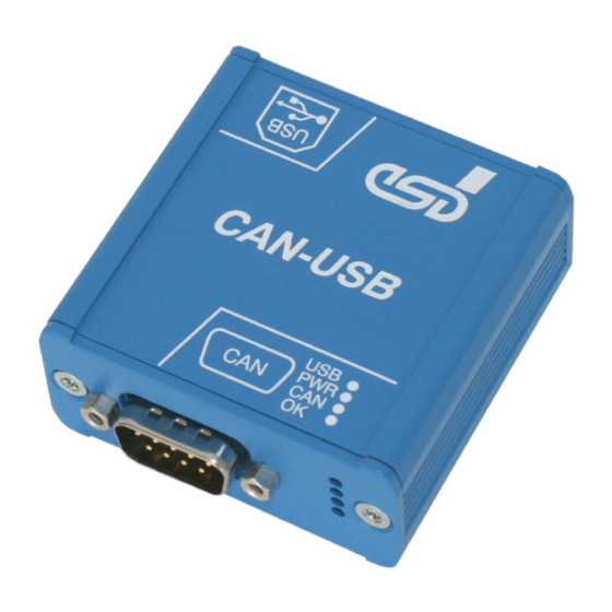
The supply voltage is fed via the USB bus. The module is equipped with four green LEDs in the front panel which indicate the current module status. CAN-USB/2 Hardware Manual • Doc. No.: C.2066.21 / Rev. 1.4 Page 7 of 25... -
Page 7: Case View With Led And Connector Description
Case View with LED and Connector Description 2. Case View with LED and Connector Description Figure 2: PCB top view Figure 3: USB Interface Page 8 of 25 Hardware Manual • Doc. No.: C.2066.21 / Rev. 1.4 CAN-USB/2... -
Page 8: Led-Displays
CAN interface is initialized and in mode ‘Automatic slow flashing Baudrate Detection’ (from firmware version 1.0.0.4 (appr. 1 Hz) and CAN driver version 2.5.2 on) Table 1: Description of LED display CAN-USB/2 Hardware Manual • Doc. No.: C.2066.21 / Rev. 1.4 Page 9 of 25... -
Page 9: Hardware Installation
Connect the CAN-USB/2-module with the USB bus of the PC Please note that the CAN bus has to be terminated at both ends! esd offers special T-connectors and termination connectors. Additionally the CAN_GND signal has to be connected to earth at exactly one point in the CAN network. -
Page 10: Technical Data
Therefore it is highly recommended to use a self-powered hub. 4.2 USB-Interface and Microcontroller USB-interface USB 2.0, bit rate up to 480 Mbit/s Microcontroller ARM7 microcontoller Table 3: USB interface and microcontroller CAN-USB/2 Hardware Manual • Doc. No.: C.2066.21 / Rev. 1.4 Page 11 of 25... -
Page 11: Can Interface
4.5 Software Support Device drivers for Windows ® and Linux ® are available. Drivers for other operating systems, especially real-time operating systems, are available on request. Page 12 of 25 Hardware Manual • Doc. No.: C.2066.21 / Rev. 1.4 CAN-USB/2... -
Page 12: Connector Assignments
CANx_GND... reference potential of the local CAN physical layer of CAN interface x (x... 1 - 4) - ... reserved for future applications, do not connect! CAN-USB/2 Hardware Manual • Doc. No.: C.2066.21 / Rev. 1.4 Page 13 of 25... -
Page 13: Usb Socket
The module may only be operated at USB nets with USB interface version numbers ≥ 1.1-interface! Using versions earlier than 2.0 reduces the data transfer rate. Pin Position: Pin Assignment: Signal Shell Shield USB socket (series B) Page 14 of 25 Hardware Manual • Doc. No.: C.2066.21 / Rev. 1.4 CAN-USB/2... -
Page 14: Correctly Wiring Electrically Isolated Can Networks
6.1.1 General Rules Note: esd grants the EC Conformity of the product, if the CAN wiring is carried out with at least single shielded single twisted pair cables that match the requirements of ISO 118982-2. Single shielded double twisted pair cable wiring as described in chapter 6.2. -
Page 15: Cabling
Use external termination plugs, because they can be rediscovered more easily than internal ● terminations within the CAN devices! 9-pin DSUB-termination connectors with male and female contacts and earth terminal are ● available as accessories Page 16 of 25 Hardware Manual • Doc. No.: C.2066.21 / Rev. 1.4 CAN-USB/2... -
Page 16: Heavy Industrial Environment (Double Twisted Pair Cable)
CAN_L CAN_GND wire shield n.c. n.c. connector case connector case Shield n.c. = not connected earth (FE) Figure. 6: CAN wiring for heavy industrial environment CAN-USB/2 Hardware Manual • Doc. No.: C.2066.21 / Rev. 1.4 Page 17 of 25... -
Page 17: Device Cabling
DSUB9 connector from ERNI (ERBIC CAN BUS MAX, order no.:154039). The usage of esd’s T-connector type C.1311.03 is not recommended for single shielded double twisted pair cables because the shield potential of the conductive DSUB housing is not looped through this T-connector type. -
Page 18: Electrical Grounding
Earthing can e.g. be made at a connector/T-connector. ● 6.4 Bus Length Optical couplers are delaying the CAN signals. esd modules typically reach a wire length of ● 37 m at 1 Mbit/s within a closed net without impedance disturbances like e.g. cable stubs >>... -
Page 19: Examples For Can Cables
Äußerer Eichwald 74535 Mainhardt BUS-Schleppflex-PUR-C (2x 2x 0.25 mm²) Order No.: 94 025 026 (UL appr.) Germany www.concab.de Note: Configured CAN cables can be ordered from esd. Page 20 of 25 Hardware Manual • Doc. No.: C.2066.21 / Rev. 1.4 CAN-USB/2... -
Page 20: Can Troubleshooting Guide
- there are no open circuits in CAN_H or CAN_L wiring - your bus system has two terminating resistors (one at each end) and that they are 120 Ω each. CAN-USB/2 Hardware Manual • Doc. No.: C.2066.21 / Rev. 1.4 Page 21 of 25... -
Page 21: Electrical Grounding
Stop all network communication. Measure the DC voltage between CAN_H and GND (see figure above). Measure the DC voltage between CAN_L and GND (see figure above). Page 22 of 25 Hardware Manual • Doc. No.: C.2066.21 / Rev. 1.4 CAN-USB/2... -
Page 22: Can Transceiver Resistance Test
Another sign for a faulty transceiver is a very high deviation between the two measured input resistance (>> 200%). CAN node CAN_H CAN_L transceiver CAN_GND disconnect Power CAN! disconnect power! Figure. 10: Measuring the internal resistance of CAN transceivers CAN-USB/2 Hardware Manual • Doc. No.: C.2066.21 / Rev. 1.4 Page 23 of 25... -
Page 23: Declaration Of Conformity
Declaration of Conformity 8. Declaration of Conformity Page 24 of 25 Hardware Manual • Doc. No.: C.2066.21 / Rev. 1.4 CAN-USB/2... -
Page 24: Order Information
Table 7: Order information PDF Manuals Manuals are available in English and usually in German as well. Available manuals are listed in the following table. Please download the manuals as PDF documents from our esd website www.esd.eu for free. Manuals Order No.
Need help?
Do you have a question about the C.2066.21 and is the answer not in the manual?
Questions and answers