Table of Contents
Advertisement
Quick Links
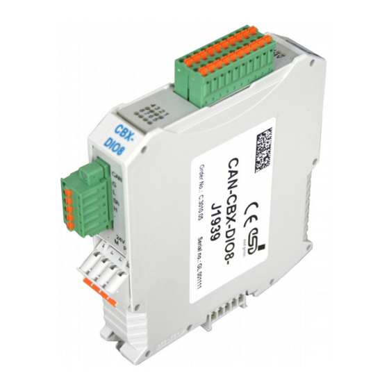
CAN-CBX-DIO8-J1939
Digital I/O module as J1939 ECU
Manual
to Product C.3010.05
CAN-CBX-DIO8-J1939
Manual • Doc. No.: C.3010.23 / Rev. 1.0
Page 1 of 33
esd electronic system design gmbh
Vahrenwalder Str. 207 • 30165 Hannover • Germany
http://www.esd.eu
Phone: +49 (0) 511 3 72 98-0 • Fax: +49 (0) 511 3 72 98-68
Advertisement
Table of Contents

Subscribe to Our Youtube Channel
Related Manuals for ESD CAN-CBX-DIO8-J1939


Summary of Contents for ESD CAN-CBX-DIO8-J1939
- Page 1 CAN-CBX-DIO8-J1939 Manual • Doc. No.: C.3010.23 / Rev. 1.0 Page 1 of 33 esd electronic system design gmbh Vahrenwalder Str. 207 • 30165 Hannover • Germany http://www.esd.eu Phone: +49 (0) 511 3 72 98-0 • Fax: +49 (0) 511 3 72 98-68...
- Page 2 The information in this document has been carefully checked and is believed to be entirely reliable. esd makes no warranty of any kind with regard to the material in this document, and assumes no responsibility for any errors that may appear in this document. In particular descriptions and technical data specified in this document may not be constituted to be guaranteed product features in any legal sense.
- Page 3 Rev. Chapter Changes versus previous version Date First English manual of CAN-CBX-DIO8-J1939 2015-03-25 Technical details are subject to change without further notice. CAN-CBX-DIO8-J1939 Manual • Doc. No.: C.3010.23 / Rev. 1.0 Page 3 of 33...
- Page 4 ● The CAN-CBX-DIO8-J1939 may become warm during normal use. Always allow adequate ventilation around the CAN- CBX-DIO8-J1939 and use care when handling. ● Do not operate the CAN-CBX-DIO8-J1939 adjacent to heat sources and do not expose it to unnecessary thermal radiation. Ensure an ambient temperature as specified in the technical data.
-
Page 5: Table Of Contents
Table of contents 1. Overview............................8 CAN-CBX-DIO8-J1939 as Part of J1939 Starter Kit...............9 Connecting Diagram......................10 2. LEDs............................11 Position of the LEDS......................11 Indication........................11 2.2.1 Source Address Error LED..................12 2.2.2 CAN State LED......................12 2.2.3 Error LED........................12 2.2.4... - Page 6 Application Programming Interface Controller Area Network Central Processing Unit CAN in Automation Hardware Input/Output Least Significant Bit Most Significant Bit n.a. not applicable Operating System Software Development Kit CAN-CBX-DIO8-J1939 Manual • Doc. No.: C.3010.23 / Rev. 1.0 Page 7 of 33...
-
Page 7: Overview
LEDs Figure 1: Block circuit diagram The CAN-CBX-DIO8-J1939 comes with eight digital input and output channels. Six of these digital IOs are outputs, two are inputs. The module operates with a MB90F497 microcontroller which buffers CAN data into a local SRAM. -
Page 8: Can-Cbx-Dio8-J1939 As Part Of J1939 Starter Kit
Overview 1.1 CAN-CBX-DIO8-J1939 as Part of J1939 Starter Kit The CAN-CBX-DIO8-J1939 (order No.:C.3010.05) is delivered in the scope of delivery of the J1939-Starter-Kit USB/2 for Windows (esd order No.: C.1130.09). PC/Notebook Power (Windows) Supply Digital I/O-Module CAN-CBX-DIO8-J1939 J1939 USB Cable... -
Page 9: Connecting Diagram
Overview 1.2 Connecting Diagram Figure 3: Connecting diagram of CAN-CBX-DIO8-J1939 Note: See also page 23 for signal assignment of the connectors. Please refer to page 30 for information on conductor connection and conductor cross section. Page 10 of 33 Manual • Doc. No.: C.3010.23 / Rev. 1.0... -
Page 10: Leds
2. LEDs 2.1 Position of the LEDS Figure 4: Connectors and LEDs The CAN-CBX-DIO8-J1939 module is equipped with 4 status LEDs and 8 LEDs for the input and output channels. 2.2 LED Indication The indicator states of the individual LEDs are described in the following chapters. In principle the... -
Page 11: Source Address Error Led
State diagram*1 FLASH 1 green LED200D FLASH 2 FLASH 3 *1... The schematic diagram is not part of this manual. Table 5: Description of the VIO LED Page 12 of 33 Manual • Doc. No.: C.3010.23 / Rev. 1.0 CAN-CBX-DIO8-J1939... -
Page 12: Leds 1 - 8
'off' input voltage of the channel x is active (the corresponding bit of the PGN is set) x .. 1 - 8 CAN-CBX-DIO8-J1939 Manual • Doc. No.: C.3010.23 / Rev. 1.0 Page 13 of 33... -
Page 13: Coding Switches
Changes of the settings therefore have to be made before switching on the module, because changes of the settings are not determined during operation. 2.3.1 Setting the Identity Number The identity No. of the CAN-CBX-DIO8-J1939 module can be set decimal from 1 to 127 or hexadecimal from 01 to 7F . -
Page 14: Software
Software 3. Software The CAN-CBX-DIO8-J1939 (esd order No.: C.3010.05) uses the same hardware as the CANopen ® module CAN-CBX-DIO8 (esd order No.: C.3010.02), but with a modified firmware. So the device acts as J1939 ECU instead. Its IOs are used as follows: IOs [1..6]: Outputs (O1 …... -
Page 15: Hardware Installation
9, 10 voltage, CAN, digital inputs, digital outputs). Please note that the CAN bus has to be terminated at both ends! esd offers special T-connectors and termination connectors. Additionally the CAN_GND signal has to be connected to earth at exactly one point in the CAN network. -
Page 16: Installation Of The Module Using Inrailbus-Connector
Now the module is mounted on the mounting rail and connected to the InRailBus via the bus connector. Connect the bus connectors and the InRailBus, if not already done. CAN-CBX-DIO8-J1939 Manual • Doc. No.: C.3010.23 / Rev. 1.0 Page 17 of 33... -
Page 17: Connecting Power Supply And Can Signals To Cbx-Inrailbus
Plug the terminal plug into the socket on the right of the mounting-rail bus connector of the InRailBus, as described in Figure 8. Then connect the CAN interface and the power supply voltage via the terminal plug. Page 18 of 33 Manual • Doc. No.: C.3010.23 / Rev. 1.0 CAN-CBX-DIO8-J1939... -
Page 18: Connection Of The Power Supply Voltage
Please note, that the impedance of the connection has to be kept low. The functional earth contact of the module does not ensure electrical safety. CAN-CBX-DIO8-J1939 Manual • Doc. No.: C.3010.23 / Rev. 1.0 Page 19 of 33... -
Page 19: Connection Of Can
Note: It is possible to remove individual devices from the CBX station without interrupting the InRailBus connection, because the contact chain will not be disrupted. Page 20 of 33 Manual • Doc. No.: C.3010.23 / Rev. 1.0 CAN-CBX-DIO8-J1939... -
Page 20: Technical Data
NS35/7,5 DIN EN 60715 width: 22.5 mm, height: 99 mm, depth: 114.5 mm Dimensions (without connectors) Weight approx. 180 g (CAN-CBX-DIO8-J1939 incl. CAN cable) Table 6: General data of the module 5.2 CPU Unit 16 bit μC MB90F497 2 Kbyte integrated... -
Page 21: Can Interface
24 V Protective circuit 20-pin PCB plug connector 0...8 V, IN_Off Input switching threshold ≥ 12 V, IN_On 30 V IN_Max Table 9: Data of the digital in/outputs Page 22 of 33 Manual • Doc. No.: C.3010.23 / Rev. 1.0 CAN-CBX-DIO8-J1939... -
Page 22: Connector Assignments
The pins 1 and 4 are connected internally. The pins 2 and 3 are connected internally. Signal Description: P24... power supply voltage +24 V ± 10 % M24... reference potential CAN-CBX-DIO8-J1939 Manual • Doc. No.: C.3010.23 / Rev. 1.0 Page 23 of 33... -
Page 23: Can
The CAN interface can be connected via the CAN connector or optionally via the InRailBus. Use the mounting-rail bus connector of the CBX-InRailBus (CAN-CBX-TBUS), see order information (page 118). Page 24 of 33 Manual • Doc. No.: C.3010.23 / Rev. 1.0 CAN-CBX-DIO8-J1939... -
Page 24: Can
9-pin DSUB, see chapter 6.2.2.1“Adapter Cable CAN-Cable-B” for further information: The assignment of the 9-pin DSUB-connector and the line connector is designed according to ® 303 part 1. CAN-CBX-DIO8-J1939 Manual • Doc. No.: C.3010.23 / Rev. 1.0 Page 25 of 33... -
Page 25: Adapter Cable Can-Cable-B
The CAN-GND signal of the cable "CAN-Cable-B" is connected via the wire shield if the cable is connected to the esd hardware. Thus the housings of the 9-pin DSUB connector is connected to CAN-GND, because no other potential is available on this connector. -
Page 26: Can And Power Supply Via Inrailbus Connector X101
CAN_GND ... reference potential of the local CAN-Physical layers P24... power supply voltage +24 V ±10 % M24... reference potential FE... functional earth contact (EMC) (connected to mounting rail potential) CAN-CBX-DIO8-J1939 Manual • Doc. No.: C.3010.23 / Rev. 1.0 Page 27 of 33... -
Page 27: Digital In/Outputs X400
1,11 100R D_OUT0 OUT4 OUT3 Microcontroller OUT2 MB90497_M09 OUT1 LOAD 22nF/ V33MLA1206 2-10, 20 100R ERR00/01* ST3/4 100R ERR02/03* ST1/2 Figure 15: Digital output circuit (Example O1) Page 28 of 33 Manual • Doc. No.: C.3010.23 / Rev. 1.0 CAN-CBX-DIO8-J1939... -
Page 28: Connector Assignment
1 and 11. These pins are connected to each other on the PCB. Note: To ensure EU Conformity a cable with a maximum wire length of 30 m has to be used for the digital inputs and digital outputs. CAN-CBX-DIO8-J1939 Manual • Doc. No.: C.3010.23 / Rev. 1.0 Page 29 of 33... -
Page 29: Conductor Connection/Conductor Cross Sections
2 conductors with same cross section, stranded, 1.0 mm² not allowed not allowed TWIN ferrules with plastic sleeve, max. Minimum AWG according to UL/cUL Maximum AWG according to UL/cUL Page 30 of 33 Manual • Doc. No.: C.3010.23 / Rev. 1.0 CAN-CBX-DIO8-J1939... -
Page 30: References
[3] Phoenix Contact GmbH & Co. KG, Blomberg. Technical data is taken from the Phoenix Contact website: https://www.phoenixcontact.com/online/portal/de; PCB plug connector - FMC 1,5/10-ST-3,5 - 1952348, downloaded 2015-02-10 CAN-CBX-DIO8-J1939 Manual • Doc. No.: C.3010.23 / Rev. 1.0 Page 31 of 33... -
Page 31: Declaration Of Conformity
Declaration of Conformity 8. Declaration of Conformity Page 32 of 33 Manual • Doc. No.: C.3010.23 / Rev. 1.0 CAN-CBX-DIO8-J1939... -
Page 32: Order Information
For detailed information about the driver availability of your special operating system, please contact our sales team. Table 10: Order information PDF Manuals For availability of English manuals see table below. Please download the manuals as PDF documents from our esd website www.esd.eu for free. Manuals Order No.
Need help?
Do you have a question about the CAN-CBX-DIO8-J1939 and is the answer not in the manual?
Questions and answers