Sign In
Upload
Manuals
Brands
ESD Manuals
Control Unit
C.3010.02
ESD C.3010.02 Manuals
Manuals and User Guides for ESD C.3010.02. We have
1
ESD C.3010.02 manual available for free PDF download: Manual
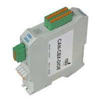
ESD C.3010.02 Manual (123 pages)
Compact I/O-Module with InRailBus
Brand:
ESD
| Category:
Control Unit
| Size: 2 MB
Table of Contents
Table of Contents
7
Overview
10
Quick Start
11
Hardware Installation
13
Connecting Diagram
13
Front Panel View
14
Indicator States
15
Operation of the CAN-Error LED
15
Operation of the Canopen-Status LED
16
Operation of the Error-LED
16
Operation of the VIO-LED
17
Special Indicator States
17
I/O-Led 1-8
18
Coding Switch
19
Setting the Node-ID Via Coding Switch
19
Setting the Baud Rate
20
Assignment of the Coding-Switch Labelling to the Name in the Schematic Diagram
20
Installation of the Module Using Inrailbus Connector
21
Connecting Power Supply and CAN-Signals to CBX-Inrailbus
22
Connection of the Power Supply Voltage
23
Connection of CAN
24
Remove the CAN-CBX Module from the Inrailbus
24
Technical Data
25
General Technical Data
25
CPU Unit
26
CAN Interface
26
Digital In-/Outputs
27
Software Support
27
Connector Pin Assignment
28
Power Supply Voltage X100
28
Can
29
CAN Interface
29
CAN Connector (X600)
30
CAN and Power Supply Voltage Via Inrailbus Connector X101
31
Digital In/Outputs X400
32
Digital Inputs
32
Digital Outputs
32
Connector Assignment Digital In-/Outputs (X400)
33
Conductor Connection/Conductor Cross Sections
34
Correct Wiring of Electrically Isolated CAN Networks
35
Standards Concerning CAN Wiring
35
Light Industrial Environment (Single Twisted Pair Cable)
36
General Rules
36
Cabling
37
Termination
37
Heavy Industrial Environment (Double Twisted Pair Cable)
38
General Rules
38
Device Cabling
39
Termination
39
Electrical Grounding
40
Bus Length
40
Examples for CAN Cables
41
Cable for Light Industrial Environment Applications (Two-Wire)
41
Cable for Heavy Industrial Environment Applications (Four-Wire)
41
CAN Troubleshooting Guide
42
Termination
42
Electrical Grounding
43
Short Circuit in CAN Wiring
43
CAN_H/CAN_L Voltage
43
CAN Transceiver Resistance Test
44
Support by Esd
44
Canopen Firmware
45
Definition of Terms
45
NMT Boot-Up
46
Canopen Object Directory
46
Communication Parameters of the Pdos
47
Accessing the Communication Parameters Via SDO Telegrams
47
Non-Volatile Storage of Parameters to EEPROM
49
Overview of Used Canopen Identifiers
50
Setting the COB-ID
50
PDO Assignment
51
Setting and Reading of the Out/Inputs
52
Status Message of the Digital Inputs
52
Digital Outputs
52
Supported Transmission Types Based on DS 301
52
Communication Profile Area
53
Used Names and Abbreviations
53
Implemented Canopen-Objects
54
Device Type
56
Error Register
57
Pre-Defined Error Field (1003 )
58
COB-ID SYNC Message (1005 )
60
Communication Cycle Period 1006
61
Manufacturer's Device Name (1008 )
62
Manufacturer's Hardware Version (1009 )
63
Manufacturer's Software Version 100A
63
Guard Time
64
Und Life Time Factor
64
Node Guarding Identifier (100E )
65
Store Parameters (1010 )
66
Restore Default Parameters (1011 )
68
COB_ID Emergency Object (1014 )
70
Inhibit Time EMCY (1015 )
71
Consumer Heartbeat Time (1016 )
72
Producer Heartbeat Time (1017 )
74
Identity Object (1018 )
75
Synchronous Counter Overflow Value 1019
77
Verify Configuration (1020 )
78
Error Behaviour Object (1029 )
79
NMT Startup (1F80 )
81
Self Starting Nodes Timing Parameters (1F91 )
82
Receive PDO Communication Parameter 1400
83
Receive PDO Mapping Parameter 1600
84
Object Transmit PDO1 Communication Parameter 1800
87
Object Transmit PDO2 Communication Parameter 1801
88
Transmit PDO1 Mapping Parameter 1A00
89
Transmit PDO2 Mapping Parameter 1A01
90
Device Profile Area
92
Implemented Objects 6000
92
Interrelation of the Implemented Objects of the Digital Inputs
93
Interrelation of the Implemented Objects of the Digital Outputs
94
Read Input 8-Bit (6000 )
95
Polarity Input 8-Bit (6002 )
96
Filter Constant Input 8-Bit (6003 )
97
Global Interrupt Enable Digital (6005 )
98
Interrupt Mask any Change 8-Bit (6006 )
99
Interrupt Mask Low to High 8-Bit (6007 )
100
Interrupt Mask High to Low 8-Bit (6008 )
101
Write Output 8-Bit (6200 )
102
Change Polarity Output 8-Bit (6202 )
103
Error Mode Output 8-Bit (6206 )
104
Error Value Output 8-Bit (6207 )
105
Manufacturer Specific Profile Area
106
Implemented Objects 2210
106
Output Errors 8-Bit (2210 )
107
Output Error Produces Emergency 8-Bit (2220 )
108
I/O Direction Mask 8-Bit (2250 )
109
VIO Voltage 16-Bit (2300 )
110
Sample Configuration (2310 )
111
Function of the Counter
112
Counter Enable (2400 )
114
Counter Preload (2401 )
115
Counter Value 16-Bit (2402H)
116
Counter Value 32-Bit (2403H)
117
Firmware Management Via Cia DSP- 302-Objects
118
Download Control Via Object 1F51
119
Download Control Via Object 1F52
120
References
121
Declaration of Conformity
122
Seite 8 von
123
Order Information
123
Advertisement
Advertisement
Related Products
ESD C.3032.02
ESD C.2066.21
ESD CAN-USB/2
ESD CAN-CBX-Pt100
ESD CAN-CBX-AO412
ESD CAN-USB/3-FD
ESD CAN-CBM-AI410
ESD CAN-CBX-DIO8
ESD CAN-CBX-DIO8-J1939
ESD C.2069.64
ESD Categories
Recording Equipment
Computer Hardware
Gateway
PCI Card
Control Unit
More ESD Manuals
Login
Sign In
OR
Sign in with Facebook
Sign in with Google
Upload manual
Upload from disk
Upload from URL