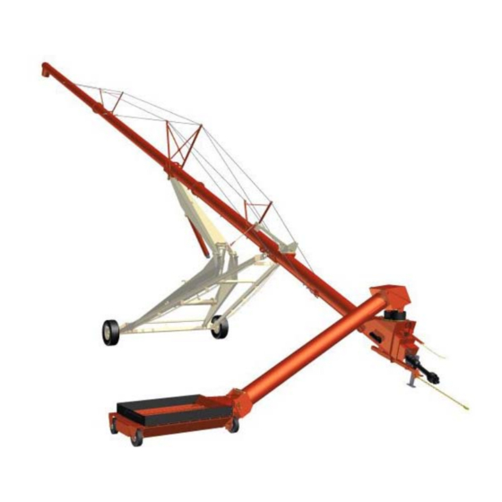
Farm King 1370 Assembly Manual
Backsaver auger
Hide thumbs
Also See for 1370:
- Operator and parts manual (268 pages) ,
- Operator and parts manual (146 pages)
Advertisement
Quick Links
Advertisement

Subscribe to Our Youtube Channel
Related Manuals for Farm King 1370


Summary of Contents for Farm King 1370
- Page 1 ASSEMBLY MANUAL BACKSAVER AUGER Models 1370, 1385, 1395, 13114 062019 FK429...
- Page 3 Assembly - 1370, 1385, 1395, 13114 Backsaver Auger ASSEMBLY Manufacturer’s Statement: For technical reasons, Farm King reserves the right to modify machinery design and specifications provided herein without any preliminary notice. Information provided herein is of descriptive nature. Performance quality may depend on soil fertility, applied agricultural techniques, weather conditions, and other factors.
- Page 4 Assembly - 1370, 1385, 1395, 13114 Backsaver Auger Hydraulic Control Valve Installation Hydraulic Winch Installation Hydraulic Wheel Motor And Wheel Installation ELECTRIC MOVER AND WINCH 1000 RPM RETRO FIT KIT Removing Intake Auger And Hopper...
-
Page 5: General Assembly Information
Assembly - 1370, 1385, 1395, 13114 Backsaver Auger GENERAL ASSEMBLY INFORMATION IMPORTANT Component Unloading And Identification Unload the crate(s) and components in flat level area of adequate size to assemble the auger. Unload crate(s) and auger components carefully, not to cause damage to any of the components. - Page 6 REAR Align the hub (Item 1) with the axle [Figure 7]. Stub Axle Mounting Bolt Sizes: LEFT • 1/2” x 1-3/4” - Models 1370, 1385, 1395 RIGHT • 3/4” x 2-1/2” - Models 13114 FRONT Install and tighten the four bolts (Item 2) and lock nuts [Figure 7].
- Page 7 Undercarriage Arm Mounting Bolt Sizes Raise and move the RH lower lift arm to the assembly area. • 5/8” x 2” - Models 1370, 1385, 1395 • 3/4” x 2-1/2” - Models 13114 Install four bolts (Item 3) and lock nuts. Do not...
- Page 8 Assembly - 1370, 1385, 1395, 13114 Backsaver Auger Figure 12 Figure 13 Locate the two lift arm axle pins. Align the LH lower lift arm (Item 1) with the two mounts (Item 2) on the axle [Figure 13]. Lift Arm Axle Pin Sizes: Install one axle pin (Item 3) through the axle •...
- Page 9 Connecting Link Pin Sizes: NOTE: Verify that there is adequate space under • 2” x 27 - 15/16” - 1370 Models the LH & RH lower lift arms for installing • 2” x 34 - 3/16” - 1385 & 1395 Models the bottom cylinder pin.
- Page 10 Assembly - 1370, 1385, 1395, 13114 Backsaver Auger Figure 18 Figure 20 Rotate the pivot yoke (Item 1) up [Figure 18]. Bottom Cylinder Pin Sizes: Lower the hydraulic cylinder and align the rod end of the cylinder with the pivot yoke (with grease •...
- Page 11 Assembly - 1370, 1385, 1395, 13114 Backsaver Auger Figure 21 Figure 23 Lift the LH & RH lower lift arms. Remove blocks Install one 1/2” flat washer on the remaining 1/2” (Item 1). Lower LH & RH lower lift arms to the x 2”...
- Page 12 Assembly - 1370, 1385, 1395, 13114 Backsaver Auger Figure 25 Figure 27 Lower the hydraulic cylinder (Item 1) onto the Align and lower the upper lift arm (Item 1) until cradle rest (Item 2) [Figure 25]. the upper lift arm is inside the two mounts (Item 2) on the lower lift arms [Figure 27].
- Page 13 Assembly - 1370, 1385, 1395, 13114 Backsaver Auger Figure 28 Figure 30 Install one 2” narrow rim washer (Item 1) and Install the top yoke pin (Item 1) through the upper cotter pin (Item 2) on the lift arm pin (both pins) lift arm mounting holes (Item 2) and pivot yoke [Figure 28].
- Page 14 Assembly - 1370, 1385, 1395, 13114 Backsaver Auger Lift Arms and Hydraulic Cylinders - 13114 Figure 32 Models Figure 34 Align the base end of the hydraulic cylinder with the mounting holes of the upper lift arm. Top Cylinder Pin Sizes: •...
- Page 15 Assembly - 1370, 1385, 1395, 13114 Backsaver Auger Figure 36 Figure 38 Place the left yoke arm (Item 1) on the outside of the link (Item 2). Position cylinder inside the link Raise the hydraulic cylinders (Item 1) and move and opposite side of the yoke arm [Figure 38].
- Page 16 Assembly - 1370, 1385, 1395, 13114 Backsaver Auger Figure 39 Figure 41 Place the right yoke arm (Item 1) on the outside of Align the RH lower lift arm (Item 1), link (Item 2) the link (Item 2). Position cylinder inside the link and LH lower lift arm (Item 3) [Figure 41].
- Page 17 Assembly - 1370, 1385, 1395, 13114 Backsaver Auger Figure 43 Figure 45 NOTE: Install a chain or strap through the base ends of the hydraulic cylinders. Connect Align the cradle rest (Item 1) with the two mounting the chain or strap to an approved lifting plates on the lift arm torque tube [Figure 45].
- Page 18 Assembly - 1370, 1385, 1395, 13114 Backsaver Auger Figure 47 Figure 49 Install a strap (Item 1) around the upper lift arm Install one 2” narrow rim washer (Item 1) and (Item 2). Connect the strap to an approved lifting 5/16”...
- Page 19 Assembly - 1370, 1385, 1395, 13114 Backsaver Auger Figure 51 Figure 53 Install a chain through the mounting hole of the Install one 2” narrow rim washer (Item 1) and left yoke arm (Item 1). Lift the left yoke arm until 5/16 x 3”...
- Page 20 Assembly - 1370, 1385, 1395, 13114 Backsaver Auger Figure 55 Wheels and Lift Arm Rest Figure 57 Install a strap (Item 1) around the center brace (Item Using a bar (Item 1), align the right cylinder with 2) on the axle. Connect the strap to an approved the mounting holes of the upper lift arm [Figure lifting device.
- Page 21 5/8” x 1-3/4” bolts, two 5/8” flat washers, and two 5/8” lock nuts [Figure 62]. Models 1370, 1385 and 1395: Install four 5/8” x 2” bolts (Item 3) and 5/8” lock nuts. Do not tighten Do not tighten at this time.
- Page 22 Assembly - 1370, 1385, 1395, 13114 Backsaver Auger Figure 63 Figure 65 13114 Models: Place the rest tube (Item 1) on top 1370, 1385, 1395 Models: Position the 1-1/2” x of the mounts (Item 2). Attach using four 5/8” x 15-5/16”...
- Page 23 Assembly - 1370, 1385, 1395, 13114 Backsaver Auger TUBES Figure 66 Assemble the tube on flat level surface. WARNING DO NOT permit bystanders to be in the work area Install a strap (Item 1) around the top tube (Item 2) when unloading and assembling components.
- Page 24 Assembly - 1370, 1385, 1395, 13114 Backsaver Auger IMPORTANT IMPORTANT When assembling the Model 1395 tube, install the 10 ft. extension tube between the top and center tubes. Figure 68 When installing the connecting shaft, the shaft will need to be aligned with and inserted into the inner collar of flighting tube.
- Page 25 Assembly - 1370, 1385, 1395, 13114 Backsaver Auger Figure 71 Figure 73 Slide the flighting from the center tube forward Install a strap (Item 1) around the end of the onto the connecting shaft. Apply thread locker to bottom tube [Figure 73].
- Page 26 Assembly - 1370, 1385, 1395, 13114 Backsaver Auger Figure 75 Figure 77 Install the chains (Item 1) onto the input box gearbox mounting bracket. Raise and move the input box to the end of the bottom tube [Figure Align the input box flighting (Item 1) with the hole 75].
- Page 27 Assembly - 1370, 1385, 1395, 13114 Backsaver Auger Bridging Figure 81 Locate and uncoil the four 1/2” cables. Place one long and one short 1/2” cable on each side of the tube assembly (longest 1/2” cable towards the outside). Figure 79...
- Page 28 Assembly - 1370, 1385, 1395, 13114 Backsaver Auger Figure 83 Figure 84 FRONT 1370 Models: Position the truss mount bracket (Item 1) below the main tube mount [Figure 84]. Figure 85 Install braces (Item 1) to the appropriate trusses. Attach each brace using 7/16" X 1-1/2" hex bolts and 7/16"...
- Page 29 Assembly - 1370, 1385, 1395, 13114 Backsaver Auger Figure 86 Figure 87 Install one truss clamp (Item 1) over the truss. Attach using two 5/8” x 2” hex bolts, two 5/8" flat washers, and two 5/8" lock nuts [Figure 87].
- Page 30 Assembly - 1370, 1385, 1395, 13114 Backsaver Auger Figure 88 Figure 89 Install one 1/2” cable clamp (Item 1) around the long 1/2” cable and to the upper truss (on the center tube or 10 ft. extension tube) (both sides) [Figure 89].
- Page 31 Assembly - 1370, 1385, 1395, 13114 Backsaver Auger Figure 91 Figure 93 Install one eyebolt (Item 1) (with eye towards discharge spout) into the hole of the mounting bracket (closest to the intake end) on the bottom Locate two cable brackets (Item 1). Install one 1/2”...
- Page 32 Assembly - 1370, 1385, 1395, 13114 Backsaver Auger Figure 94 Figure 95 Thread the cable through the eyebolt and around the thimble (both sides). Pull cable as tight as possible. Loop the cable around the thimble. Install one Install one 1/2” x 2” bolt (Item 1) through the cable clamp (Item 1) around the cable.
- Page 33 Assembly - 1370, 1385, 1395, 13114 Backsaver Auger Figure 96 Figure 98 NOTE: Cable lengths may vary. The following is a starting point and cables may need to be tightened more or loosened depending on the cable length. 4 FT.
- Page 34 Assembly - 1370, 1385, 1395, 13114 Backsaver Auger NOTE: The following images may not show your Figure 101 exact bearing assembly as it appears but the procedure is correct. Figure 99 Align the spout clamp (Item 1) and discharge spout (Item 2) with discharge opening in the top tube [Figure 101].
- Page 35 Assembly - 1370, 1385, 1395, 13114 Backsaver Auger Truss Beams - 13114 Models Figure 104 Figure 102 Install the truss fastener / beam assembly (Item 1) Install the T-bar (Item 1) as shown, install a bolt onto the lower tube #1 truss beam mount (Item 2) and nut (Item 2) through the hitch mount and T-bar [Figure 104].
- Page 36 Assembly - 1370, 1385, 1395, 13114 Backsaver Auger Figure 106 Figure 108 ANGLE WIDE SIDE NOTCH ANGLE Raise the truss beam assembly (Item 1) and the truss beam (Item 2) [Figure 106]. The truss support brackets (Item 1) have one, two,...
- Page 37 Assembly - 1370, 1385, 1395, 13114 Backsaver Auger Figure 110 Figure 112 WIDE SIDE Install the truss beam (Items 1 & 2) onto the tube Raise and align the truss beam (Item 1), install the #2 truss beam mount [Figure 110].
- Page 38 Assembly - 1370, 1385, 1395, 13114 Backsaver Auger Figure 113 Figure 115 Install the truss beam (Items 1 & 2) onto the tube Raise and align truss beam (Item 1), install the #3 truss beam mount [Figure 113]. 1-1/4” pin (Item 2), 1-1/4” narrow rim washer and 1/4”...
- Page 39 Assembly - 1370, 1385, 1395, 13114 Backsaver Auger Figure 117 Figure 119 Install the 1-1/4” nut (Item 1) onto the truss Raise the truss beam assembly (Item 1) and the fastener (Item 2). Install the truss fastener into the truss beam (Item 2) [Figure 119].
- Page 40 Assembly - 1370, 1385, 1395, 13114 Backsaver Auger Figure 121 Figure 123 WIDE SIDE Place the truss support bracket (four notches) (Item 1) between the left side and right side truss beams (wide side of support bracket toward the lower tube) [Figure 121].
- Page 41 Assembly - 1370, 1385, 1395, 13114 Backsaver Auger Figure 124 Figure 126 NOTE: The castle nut has been removed in the left picture to show cotter pin hole options. Align the spout clamp (Item 1) and discharge With the tube assembly complete, tighten the...
- Page 42 Assembly - 1370, 1385, 1395, 13114 Backsaver Auger Trusss Beam Identification - 13114 Models Figure 127 Top of Auger Tabs to inside Tabs to inside Tabs to inside Tabs to inside Tabs to inside Bottom of Auger...
- Page 43 Assembly - 1370, 1385, 1395, 13114 Backsaver Auger Truss Beams [Figure 127] 83.69” 260” 145.42” 145.42” 262.38” 260” 121.08” 214.19” 53.50”...
- Page 44 Assembly - 1370, 1385, 1395, 13114 Backsaver Auger Trusss Brace Identification - 13114 Models Figure 128 Top of Auger 4 Notches 3 Notches Qty 2 2 Notches Qty 2 1 Notch Qty 6 Bottom of Auger...
- Page 45 Assembly - 1370, 1385, 1395, 13114 Backsaver Auger Truss Braces [Figure 128] 1 Notch 52.24” 2 Notches 64.34” 3 Notches 50.46” 4 Notches 36.64” 103.70” 114.50” 84.85”...
- Page 46 Assembly - 1370, 1385, 1395, 13114 Backsaver Auger TUBE AND UNDERCARRIAGE - 1370, Figure 129 1385, 1395 MODELS Install the tube on the undercarriage on a flat level surface. WARNING With the strap (Item 1) installed around the center tube and connected to an approved lifting device,...
- Page 47 Assembly - 1370, 1385, 1395, 13114 Backsaver Auger Figure 131 Figure 133 Remove the two 7/16” x 1-1/2” bolts (Item 1), Remove the 5/8” x 1-3/4” bolt (Item 1), 5/8” lock nut 7/16” lock nut and 7/16” flat washers from the and 5/8”...
- Page 48 Connect the strap to an approved lifting device and raise the lower lift arm assembly [Figure 137]. 1370 Models: Position the lift arm cradle (Item 2) under the undercarriage arm mount. Install bolt (Item 3) and lock nut [Figure 137].
- Page 49 Assembly - 1370, 1385, 1395, 13114 Backsaver Auger Figure 138 Figure 139 Install two grease zerks (Item 1) to the axle end of the LH & RH lower lift arms [Figure 139]. Figure 140 With the upper lift arm (Item 1) resting on the lift...
- Page 50 Assembly - 1370, 1385, 1395, 13114 Backsaver Auger Figure 141 IMPORTANT Check over undercarriage, verify all bolts are tight, all zerks are greased and cotter pins bent over. Install two grease zerks (Item 1) into the connecting link [Figure 141].
- Page 51 Assembly - 1370, 1385, 1395, 13114 Backsaver Auger TUBE AND UNDERCARRIAGE - 13114 Figure 143 MODELS Install the tube on the undercarriage on a flat level surface. WARNING DO NOT permit bystanders to be in the work area when unloading and assembling components.
- Page 52 Assembly - 1370, 1385, 1395, 13114 Backsaver Auger Figure 145 Figure 147 Raise the front of the undercarriage (Item 1) and Lower the tube assembly and align the holes of align the holes of the undercarriage with the the tube undercarriage mounting plate (Item 1) mount holes on the tube [Figure 145].
- Page 53 Assembly - 1370, 1385, 1395, 13114 Backsaver Auger Figure 149 Figure 150 Install the upper lift arm pin (Item 1) through the Align the cross brace tube (Item 1) with the bridging plate and upper lift arm [Figure 149]. lower cross brace mounts on the left and right undercarriage arms [Figure 150].
- Page 54 Assembly - 1370, 1385, 1395, 13114 Backsaver Auger Figure 152 IMPORTANT Place chock blocks in front and behind the tires of the undercarriage to prevent the auger assembly from moving. Figure 151 Tighten the sixteen 1/2” bolts (Item 1) and nuts on the torque tube (Item 2) [Figure 152].
- Page 55 Assembly - 1370, 1385, 1395, 13114 Backsaver Auger Figure 153 IMPORTANT Fully tighten tube assembly hardware before installing the tube assembly onto the undercarriage. Install one grease zerk (Item 1) into the upper lift arm [Figure 153]. Figure 154 Install two grease zerks (Item 1) into the upper lift arm [Figure 154].
- Page 56 Assembly - 1370, 1385, 1395, 13114 Backsaver Auger INTAKE AUGER Figure 157 Figure 155 Lower the intake auger, align the u-joint (Item 1) with the top gearbox shaft (Item 2) of the input Install the intake spacers (Item 1) on the top of the box [Figure 157].
- Page 57 Assembly - 1370, 1385, 1395, 13114 Backsaver Auger HOPPER Figure 159 Figure 161 Rotate the intake auger (Item 1) 90° towards the right side of the auger [Figure 159]. Install chains (Item 1) onto the hopper (Item 2) Figure 160 [Figure 161].
- Page 58 Assembly - 1370, 1385, 1395, 13114 Backsaver Auger Figure 163 Figure 165 Install a ratchet strap (Item 1) onto the bracket (Item 2) on the top of the hopper (connect the opposite end of the ratchet strap to the mounting bracket on the top of the intake auger) [Figure 163].
- Page 59 Assembly - 1370, 1385, 1395, 13114 Backsaver Auger Figure 166 Figure 168 Align the hinged intake auger cover (Item 1) with Place the rubber edge (Item 1) inside the outer the four mounting holes in the hopper. Install four flange of the hopper [Figure 168].
-
Page 60: Safety Chain
Assembly - 1370, 1385, 1395, 13114 Backsaver Auger SAFETY CHAIN Figure 169 Figure 170 Install the safety chain loop (Item 1) into the opening on the bottom side of the hitch, install Align the end of the rubber edge with the two one 3/4”... -
Page 61: Pto Driveline
Assembly - 1370, 1385, 1395, 13114 Backsaver Auger HYDRAULIC HOSE HOLDER PTO DRIVELINE Figure 172 Figure 174 Install the hydraulic hose holder (Item 1) onto Push back on the collar (Item 1) and install the shaft the mounting bracket located on the top of the into the gearbox until the collar slides forward, gearbox (above the hitch) [Figure 172]. - Page 62 Assembly - 1370, 1385, 1395, 13114 Backsaver Auger HAND WINCH AND CABLE Figure 177 Figure 176 Locate the winch cable. Install the open end of the cable (Item 1) through the slot and over the pulley on the top of the lift boom [Figure 177].
- Page 63 Assembly - 1370, 1385, 1395, 13114 Backsaver Auger HOPPER SAFETY HOOK IMPORTANT Figure 180 Do not remove the drum to install the cable. Figure 179 Install the quick link (Item 1) through the eye of the hook (Item 2). Install the quick link onto the safety chain at the desired location.
- Page 64 Assembly - 1370, 1385, 1395, 13114 Backsaver Auger HYDRAULICS - 1370, 1385, 1395 Install the 08 MNPT x 08 MNPT 90° elbow into the flow control valve. MODELS Install the 08 x 00 MJIC x 08 MNPT hydraulic hose Hydraulic Cylinder Hose Installation into the 08 FNPT One Way Flow Control Valve.
- Page 65 Assembly - 1370, 1385, 1395, 13114 Backsaver Auger Figure 184 Figure 186 Install and tighten the 08 x 010 MJIC x 08 MNPT Locate one 90° elbow (Item 1) and place in a vise hydraulic hose (Item 1) into the tube (Item 2) on [Figure 186].
- Page 66 Assembly - 1370, 1385, 1395, 13114 Backsaver Auger Figure 188 Install hose assembly (Item 1) into the hydraulic tube (Item 2) on the bottom tube section. Route the hose towards the hitch and install into the hydraulic hose holder [Figure 188].
- Page 67 Assembly - 1370, 1385, 1395, 13114 Backsaver Auger HYDRAULICS - 13114 MODELS Figure 190 Hydraulic Cylinder Hose Installation IMPORTANT When installing servicing hydraulic systems, clean the work area before assembly or disassembly and keep all parts clean. Always use caps and plugs on hoses, hydraulic tubes and ports to keep dirt out.
- Page 68 Assembly - 1370, 1385, 1395, 13114 Backsaver Auger Figure 192 Figure 194 Install and tighten the two hoses from the base Locate and install the two hydraulic hoses (Item 1) ends of the cylinders onto the tee fitting (Item 1) on the rod end of the cylinders [Figure 194].
- Page 69 Assembly - 1370, 1385, 1395, 13114 Backsaver Auger Figure 196 Figure 198 Install and tighten the two hoses from the rod Route the rod end and base end hydraulic hoses ends of the cylinders onto the tee fitting (Item 1) up to the hydraulic tubes on the #2 tube (on the right side, just in front of the upper lift arm pin).
- Page 70 Assembly - 1370, 1385, 1395, 13114 Backsaver Auger Figure 200 Figure 202 Apply teflon tape to the threads (Item 1) of the hydraulic hose fitting, then install and tighten the male quick coupler fitting (Item 2) [Figure 200]. Locate one 90° elbow (Item 1) and place in a vise Repeat for second quick coupler hose.
- Page 71 Assembly - 1370, 1385, 1395, 13114 Backsaver Auger HYDRAULIC HOPPER MOVER AND Figure 203 WINCH Hydraulic Control Valve Installation Figure 205 Install hose assembly (Item 1) onto the right side hydraulic tube [Figure 203]. Install hose / valve assembly (Item 2) onto the left side hydraulic tube [Figure 203].
- Page 72 Assembly - 1370, 1385, 1395, 13114 Backsaver Auger Figure 207 Figure 209 Apply teflon tape to the threads (Item 1) of the Install the mounting bracket (Item 1) onto the valve hydraulic hose fitting, then install and tighten the block using three 1/4” x 2-3/4” bolts, three 1/4” flat male quick coupler fitting (Item 2) [Figure 209].
- Page 73 Assembly - 1370, 1385, 1395, 13114 Backsaver Auger Hydraulic Winch Installation Figure 212 Remove the cable from the hand winch (if equipped). Remove the hand winch from the input box (if equipped). Figure 211 Align the winch with four holes (Item 1) in the winch mounting plate on the top of the bottom tube [Figure 212].
-
Page 74: Cut Hazard
Assembly - 1370, 1385, 1395, 13114 Backsaver Auger Figure 214 Figure 215 Install one lock washer and flat washer onto the Route the winch cable (Item 1) through the end four bolts pulley of the lift boom, down through the bottom... - Page 75 Assembly - 1370, 1385, 1395, 13114 Backsaver Auger Figure 217 Figure 219 Position one bracket half (Item 1) on the tube, approximately 36” from the input box. Position the bolt (Item 2) angled away from the top center Loop the tail end (Item 1) of the cable and feed of the tube [Figure 219].
- Page 76 Assembly - 1370, 1385, 1395, 13114 Backsaver Auger Figure 220 Figure 222 Install and tighten two 90° elbow fittings (Item 1) Using four bolts (Item 1) (two each side) and lock into the winch [Figure 220]. nuts, install the winch shield (Item 2) onto the winch mounting plate (Item 3) [Figure 222].
- Page 77 Assembly - 1370, 1385, 1395, 13114 Backsaver Auger Hydraulic Wheel Motor And Wheel Installation Figure 226 Figure 224 RIGHT LEFT Right hand (RH) and left hand (LH) sides of the hopper are as viewed from the end of the hopper,...
- Page 78 Assembly - 1370, 1385, 1395, 13114 Backsaver Auger Figure 228 Figure 229 Position one half clamp with bolt (Item 1) just Position one half clamp with bolt (Item 1) just above the two lower decals on the intake auger below the intake elbow with the bolt (Item 2) tube with the bolt (Item 2) centered on the bottom centered on the bottom of the tube [Figure 229].
- Page 79 Assembly - 1370, 1385, 1395, 13114 Backsaver Auger Figure 230 Figure 232 Locate one 60” hydraulic hose (Item 1) and two Install the left wheel motor hydraulic hose (Item 84” hydraulic hoses (Item 2) [Figure 230]. 1) onto the upper left fitting on the valve block [Figure 232].
- Page 80 Assembly - 1370, 1385, 1395, 13114 Backsaver Auger ELECTRIC MOVER AND WINCH Figure 234 NOTE: The following images may not show your winch exactly as it appears but the procedure is correct. Remove the cable from the hand winch (if equipped).
- Page 81 Assembly - 1370, 1385, 1395, 13114 Backsaver Auger Figure 236 Figure 237 Install one lock washer and flat washer onto the Route the winch cable (Item 1) through the end four bolts pulley of the lift boom, down through the bottom...
- Page 82 Assembly - 1370, 1385, 1395, 13114 Backsaver Auger Figure 239 Figure 241 RIGHT LEFT Install wiring harness connector (Item1) to right hand (R) electric motor wheel harness connector (Item 2) as shown [Figure 241]. Right hand (RH) and left hand (LH) sides of the...
- Page 83 Assembly - 1370, 1385, 1395, 13114 Backsaver Auger 1000 RPM RETRO FIT KIT Figure 243 Removing Intake Auger And Hopper WARNING DO NOT permit bystanders to be in the work area when unloading and assembling components. DO NOT work under suspended parts.
- Page 84 Assembly - 1370, 1385, 1395, 13114 Backsaver Auger Figure 245 WARNING AVOID INJURY OR DEATH Hydraulic fluid escaping under pressure can have sufficient force to enter a person’s body by penetrating the skin. This can cause serious injury and possible death if proper medical treatment by a physician familiar with this injury is not received immediately.
- Page 85 Assembly - 1370, 1385, 1395, 13114 Backsaver Auger Figure 247 Figure 249 Remove the two bolts (Item 1) and ring clamp (Item 2). Repeat to remove the three remaining Install chains (Item 1) inside the input box [Figure ring clamps [Figure 247].
- Page 86 Assembly - 1370, 1385, 1395, 13114 Backsaver Auger Figure 251 Figure 253 Remove the eight 7/16” x 1-1/4 bolts (Item 1) and 7/16” lock nuts around the mounting flanges of the bottom tube and input box [Figure 251]. Figure 252 Lower the input box to the ground with the tube mounting flange flat on the ground [Figure 253].
- Page 87 Assembly - 1370, 1385, 1395, 13114 Backsaver Auger Figure 254 Figure 256 Remove the four bolts (Item 1), then remove guard Release the two latches (Item 1) and open clean (Item 2) [Figure 254]. out cover (Item 2) [Figure 256].
- Page 88 Assembly - 1370, 1385, 1395, 13114 Backsaver Auger Figure 258 Figure 260 Remove the bolt (Item 1) from input box flighting Install straps (Item 1) through the drive assembly [Figure 258]. [Figure 260]. Figure 259 Connect the straps to an approved lifting device.
- Page 89 Assembly - 1370, 1385, 1395, 13114 Backsaver Auger Figure 262 Figure 264 Install the square end of the bar shaft (Item 1) into Install a strap (Item 1) around the 1000 RPM the input box flighting [Figure 262]. gearbox (Item 2). Connect the strap to an approved lifting device [Figure 264].
- Page 90 Assembly - 1370, 1385, 1395, 13114 Backsaver Auger Figure 265 Figure 267 Install the eight bolts (Item 1) through the 1000 PRM gearbox, spacer plate and input box. Install Raise the hitch (Item 1) and align with the mounting one lock nut on each bolt and tighten [Figure 265].
- Page 91 Assembly - 1370, 1385, 1395, 13114 Backsaver Auger Figure 269 Align the input box flighting (Item 1) with the hole in the bottom tube flighting. Install bolt (Item 2) and lock nut. Tighten bolt and lock nut [Figure 269]. Figure 270 Move the input box towards the bottom tube until the two mounting flanges make contact.
- Page 92 Assembly - 1370, 1385, 1395, 13114 Backsaver Auger...
- Page 94 www.farm-king.com 301 Mountain Street South Morden, MB R6M 1X7 E-mail: info@buhler.com www.farm-king.com Equipment shown is subject to change without notice. ©2019 Buhler Trading Inc. Printed in Canada TSX:BUI a division of Buhler Industries Inc.
Need help?
Do you have a question about the 1370 and is the answer not in the manual?
Questions and answers