Sign In
Upload
Manuals
Brands
Farm King Manuals
Farm Equipment
1395
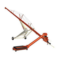
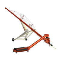
User Manuals: Farm King 1395 Grain Augers
Manuals and User Guides for Farm King 1395 Grain Augers. We have
3
Farm King 1395 Grain Augers manuals available for free PDF download: Operator And Parts Manual, Assembly Manual
Farm King 1395 Operator And Parts Manual (268 pages)
Backsaver Auger
Brand:
Farm King
| Category:
Farm Equipment
| Size: 11 MB
Table of Contents
Table of Contents
3
Safety
5
Introduction
7
Owner's Information
9
Equipment Identification
10
Table of Contents
11
Safety Instructions
13
Safe Operation Is the Operator's Responsibility
13
Safe Operation Needs a Qualified Operator
13
Use Safety Rules
14
Transport Safety
14
Operation Safety
15
Service and Maintenance Safety
15
Safety Rules for Power Take-Off (PTO) Driven Equipment
15
Machine Requirements and Capabilities
16
Operation
17
Fire Prevention
17
Maintenance
17
Starting
17
Electrical
17
Hydraulic System
17
Fueling
17
Spark Arrester Exhaust System
17
Welding and Grinding
18
Fire Extinguishers
18
Operating Safety Zone
19
Safety Zone Identification
19
Safety Signs (Decals)
20
Equipment Decals and Signs
23
Safety Sign-Off Form
24
Table of Contents
25
General Assembly Information
27
Component Unloading and Identification
27
Base Group
28
Undercarriage Assembly
28
1370, 1385 & 1395 Link and Yoke Assembly
31
13114 Link and Yoke Assembly
36
All Models - Tire and Lift Arm Rest Tube Assembly
42
Tube Assembly
45
1370, 1385 & 1395 Bridging Assembly
49
13114 Truss Beam Assembly
57
13114 Truss Beam Identification
64
13114 Cross Brace Plate / Truss Support Bracket Identification
66
1370, 1385 & 1395 Installing Tube on Undercarriage
68
13114 Installing Tube on Undercarriage
73
Installing the Intake Auger
78
Hopper Assembly and Installation
79
Safety Chain Installation
82
Manual Holder Installation
82
Hydraulic Hose Holder Installation
83
Jack Installation
83
PTO Driveline Installation
83
Lift Boom Arm Installation
83
Hand Winch and Cable Installation
84
Hopper Safety Hook Installation
85
1370, 1385, 1395 Hydraulic Assembly
86
Hydraulic Cylinder Hose Installation
86
13114 Hydraulic Assembly
89
Hydraulic Cylinder Hose Installation
89
Hydraulic Mover and Winch (Optional)
93
Hydraulic Control Valve Installation
93
Hydraulic Winch Installation (Optional)
95
Hydraulic Wheel Motor and Wheel Installation (Optional)
99
Electric Mover and Winch (Optional)
102
Electric Winch Installation
102
Electric Wheel Motor and Wheel Installation
105
1000 Rpm Retro Fit Kit
107
Removing Intake Auger and Hopper
107
Table of Contents
117
General Information
119
Pre - Operation Checklist
119
Break - in Checklist
120
Tractor Requirements
121
Entering and Leaving the Operator's Position
122
Initial Set-Up
122
Connecting the Backsaver Auger to the Tractor
122
Connecting the PTO Driveline
123
PTO Driveline
125
Connecting Hydraulic Hoses
128
Auger Operation
129
Manual Hopper and Winch
129
Hydraulic Hopper Mover and Winch (if Equipped)
131
Adjusting Flow Control Valve
132
Auger Placement
133
Unloading Belly Dump Units
134
Unloading Rear and Side Dump Units
136
Transporting
138
Requirements
138
Transporting Guidelines
138
Transporting Procedure
139
Maintenance
141
Troubleshooting
143
Chart
143
Service Schedule
144
Maintenance Intervals
144
Lubrication
145
Recommendations
145
Locations
145
Hopper Dual Auger Drive Chains
148
4168 Upper Gearbox
148
Cleaning and Inspection
148
Axle
149
Wheel Lug Nut Torque
149
Tire / Wheel Replacement
149
1370, 1385, and 1395 Bridging Cables
150
Cable Inspection
150
Lubricating
150
Cleaning
150
Lower and Upper Bridging Cables
150
Safety Sign (Decal) Installation
152
Procedure
152
Storage and Return to Service
153
Storage
153
Return to Service
153
Parts Identification
155
13" Backsaver Auger
159
Components
159
General Information
159
Bs1370 Undercarriage
160
Lifting Arms - Bs1370
162
Stub Axle Assembly - Bs1370
164
Bs1385 Undercarriage
166
Lifting Arms - Bs1385
168
Stub Axle Assembly - Bs1385 / Bs1395
170
Bs13114 Undercarriage
172
Lifting Arms - Bs13114
174
Stub Axle Assembly - Bs13114
176
Tube Layout and Bridging - Bs1370
178
Tube Layout and Hydraulics - Bs1370
180
Bs1370 Top Tube Assembly
182
Bs1370 Bottom Tube Assembly
184
Bs1370 Center Tube Assembly
185
Tube Layout and Bridging - Bs1385
186
Tube Layout and Hydraulics - Bs1385 / Bs1395
188
Bs1385 Top Tube Assembly
190
Bs1385 Bottom Tube Assembly
191
Bs1385 Center Tube Assembly
191
Tube Extension 10' and Bridging - Bs1395
192
Bs13 10' Extension Assembly
193
Tube Layout - Bs13114
194
Bs13114 Tube #4 (Top) Assembly
196
Bs13114 Tube #1 (Bottom) Assembly
197
Bs13114 Tube #3, 4 (Center) Assembly
197
Tube Bridging - Bs13114
198
Tube Bridging - Bs13114
200
Intake Auger
202
Intake Auger Assembly
204
Input Box Elbow Assembly - Bs13
206
Intake Auger Tube Assembly
207
Input Box (1370, 1385, 1395)
208
Bs13 Input Box Assembly
210
Input Box Assembly (13114)
212
Idler Assembly
214
Single Flighting Hopper
216
Single Flighting Hopper
218
Single Flighting Hopper
219
Multi Flighting Hopper
220
Multi-Flighting Hopper Assembly
222
Multi-Flighting Hopper Assembly
224
Bs13 Lift Boom Assembly
226
Pto 1370
228
Pto 1385, 1395, 13114
229
Bs13 Hydraulic Mover and Winch (Option)
232
Bs13 Hydraulic Winch (Option)
234
Bs13 Hydraulic Mover (Option)
236
Hydraulic Mover Valve Assembly
238
Bs Safety Light Kit (Option)
240
Shipping Kit and Bundle Numbers
243
Shipping Kit and Bundle Numbers
245
Y1370TMR 13" X 70' Backsaver Auger W/Single Flighting Hopper
245
Y1370TMMR 13" X 70' Backsaver Auger W/Multi-Flighting Hopper
245
Y1385TMR 13" X 85' Backsaver Auger W/Single Flighting Hopper
246
Y1385TMMR 13" X 85' Backsaver Auger W/Multi-Flighting Hopper
246
PBMY13114E 13" X 114' Backsaver Auger W/Electric
247
PBMY13114H 13" X 114' Backsaver Auger W/Hydraulics
248
Optional Bundle Numbers
249
Options Available
249
Specifications
251
Warranty
261
Alphabetical Index
265
Advertisement
Farm King 1395 Operator And Parts Manual (146 pages)
BACKSAVER AUGER
Brand:
Farm King
| Category:
Tools
| Size: 16 MB
Table of Contents
Table of Contents
3
Warranty Registration Form
5
Introduction
7
Safety
11
Safe Operation
13
Safety Alerts
13
Safety Instructions
13
Safety Rules for Power Take-Off (PTO) Driven Equipment
14
Machine Requirements and Capabilities
15
Transport Safety
15
Electrical
16
Fire Extinguishers
16
Fire Prevention
16
Fueling
16
Hydraulic System
16
Maintenance
16
Operation
16
Welding and Grinding
16
Operating Safety Zones
17
Equipment & Safety Signs (Decals)
18
Safety Sign-Off Form
22
Operation
23
General Information
25
Pre - Operation Checklist
25
Break - in Checklist
26
Drawbar Adjustment
27
Tractor and Gas Engine Requirements
27
Connecting to Tractor
28
Entering & Leaving the Operator's Position
28
Entering the Operator's Position
28
Hitching the Equipment
28
Leaving the Operator's Position
28
Connecting the P to Driveline
29
PTO Driveline Bottoming out Check
31
PTO Driveline Length Check
31
Reducing the PTO Driveline Length
32
PTO Driveline Engagement Check
33
Connecting Hydraulic Hoses
34
Auger Operation
35
Main Lift Cylinder Adjust
36
Auger Placement
37
Unloading Belly Dump Units
38
Unloading Rear and Side Dump Units
40
Requirements
41
Transportation
41
Transporting Procedure
42
Maintenance
45
Troubleshooting
47
Service Schedule
48
Locations
49
Lubrication
49
Recommendations
49
Axles
53
Tire / Wheel Replacement
53
Tire Pressure
53
Wheel Lug Nut Torque
53
Bridging Cables
54
Cable Inspection
54
Cleaning
54
Lubrication
54
Tension Adjust
54
Return to Service
56
Safety Sign (Decal) Installation
56
Storage
56
Storage and Return to Service
56
Electric Hopper Control Box Troubleshooting
57
Hopper will Not Move Left or Right
57
Hopper will Only Move in One Direction
57
Remote Control Functions Correctly but the Move-Left/Right Switches on the Box Do Not
57
Remote Control Functions Correctly but the Raise/Lower Switches on the Box Do Not
58
Winch will Not Raise or Lower
58
Winch will Only Rotate in One Direction
58
Electric Hopper Remote Operation
59
Indicator Lights
59
Recharging
59
Teach ID Code
59
Part Identification - Control Box Sz000997
60
Parts Identification
63
General Parts Information
66
Undercarriage - 70 Models
66
Undercarriage - 85, 95 Models
68
Undercarriage - 114 Models
70
Stub Axle - 70 Models
72
Stub Axle - 85, 95 Models
73
Stub Axle - 114 Models
74
Lift Arms - 70 Models
76
Lift Arms - 85, 95 Models
78
Lift Arms - 114 Models
80
Tubes - 70 Models
82
Tubes - 85 Models
84
Tubes - 95 Models
86
Tubes - 114 Models
90
First Tube (Intake)
92
Second Tube
92
Tube Components - 70 Models
92
Third Tube
93
First Tube (Intake)
94
Second Tube
94
Tube Components - 85 Models
94
Third Tube
95
First Tube (Intake)
96
Second Tube
96
Tube Components - 95 Models
96
Third Tube
97
Third Tube
98
First Tube (Intake)
99
Tube Components - 114 Models
99
Second Tube
100
Third Tube
100
Fourth Tube
101
Bridging - 114 Models
102
Input Box - 70, 85, 95 Models
104
Input Box - 114 Models
108
Idler
112
M1000 Gearbox Input Box - 70, 85, 95 Models
114
M1000 Gearbox Input Box - 114 Models
118
Intake Auger
122
Single-Flighting Hopper
124
Multi-Flighting Hopper
126
Pto - 70, 85, 95 Models
128
Pto - 114 Models
129
Pto with M1000 Gearbox
130
Specifications
131
1370 Models
133
Dimensions
133
1385 / 1395 Models
134
13114 Models
135
13114 Models
136
Hardware Torque Values
137
Metric Chart
137
Imperial Chart
138
Flare Fitting
139
Hydraulic Connection
139
O-Ring Face Seal Connection
139
O-Ring Fitting (Straight Thread)
139
Port Seal (O-Ring Boss) Fitting
139
Tubelines and Hoses
139
Warranty
141
Farm King 1395 Assembly Manual (94 pages)
BACKSAVER AUGER
Brand:
Farm King
| Category:
Tools
| Size: 14 MB
Table of Contents
General Assembly Information
5
Electrocution Hazard
5
Safety Chain
60
Manual Holder
60
Pto Driveline
61
Cut Hazard
74
Advertisement
Advertisement
Related Products
Farm King 1370
Farm King 1385
Farm King 13114
Farm King 1342
Farm King 1352
Farm King 1362
Farm King 1450
Farm King 12112
Farm King 12122
Farm King 1684
Farm King Categories
Farm Equipment
Snow Blower
Compact Loader
Tools
Lawn Mower
More Farm King Manuals
Login
Sign In
OR
Sign in with Facebook
Sign in with Google
Upload manual
Upload from disk
Upload from URL