
Related Manuals for Farm King 1370


Summary of Contents for Farm King 1370
- Page 1 OPERATOR AND PARTS MANUAL BACKSAVER AUGER Models 1370, 1385, 1395, 13114 062022 FK428...
-
Page 3: Table Of Contents
1370, 1385, 1395, 13114 Backsaver Auger TABLE OF CONTENTS Manufacturer’s Statement: For technical reasons, Farm King reserves the right to modify machinery design and specifications provided herein without any preliminary notice. Information provided herein is of descriptive nature. Performance quality may depend on soil fertility, applied agricultural techniques, weather conditions, and other factors. - Page 4 1370, 1385, 1395, 13114 Backsaver Auger...
-
Page 5: Warranty Registration Form
Customer / Owner Signature: Remove this Warranty Registration Form from the Operator And Parts Manual. Make two copies of the form. Send original Warranty Registration Form to Farm King. Give one copy to the customer and the dealer will keep one copy. - Page 6 Warranty Registration Form - 1370, 1385, 1395, 13114 Backsaver Auger...
-
Page 7: Introduction
Farm King equipment. READ AND UNDERSTAND THIS OPERATOR AND PARTS MANUAL BEFORE OPERATING YOUR FARM KING EQUIPMENT. If you have any questions, see your Farm King dealer. This manual may illustrate options and accessories not installed on your Farm King equipment. - Page 8 Introduction - 1370, 1385, 1395, 13114 Backsaver Auger...
- Page 9 Introduction - 1370, 1385, 1395, 13114 Backsaver Auger OWNER’S INFORMATION Serial Number Location Please enter the model and serial number in the Thank you for your decision to purchase a Farm space provided for easy reference. King Backsaver Auger. To ensure maximum...
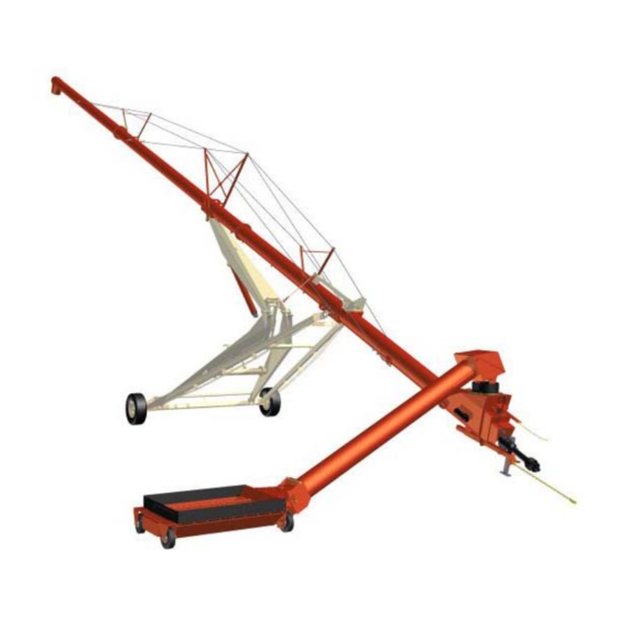
- Page 10 Introduction - 1370, 1385, 1395, 13114 Backsaver Auger EQUIPMENT IDENTIFICATION DISCHARGE SPOUT BRIDGING BOOM HYDRAULIC INPUT BOX CYLINDER ELBOW UNDERCARRIAGE DRIVELINE WHEEL INTAKE AUGER JACK SAFETY CHAIN HOPPER...
-
Page 11: Safety
Safety - 1370, 1385, 1395, 13114 Backsaver Auger SAFETY SAFETY INSTRUCTIONS Safety Alerts Safe Operation Safety Rules Safety Rules For Power Take-Off (PTO) Driven Equipment Machine Requirements And Capabilities Transport Safety FIRE PREVENTION Maintenance Operation Fire Extinguishers Electrical Hydraulic System... - Page 12 Safety - 1370, 1385, 1395, 13114 Backsaver Auger...
-
Page 13: Safety Instructions
Safety - 1370, 1385, 1395, 13114 Backsaver Auger SAFETY INSTRUCTIONS Safe Operation Safety Alerts WARNING Safety Alert Symbol Operators must have instructions before operating the machine. Untrained operators can cause injury This symbol with a warning statement means: or death. -
Page 14: Safety Rules For Power Take-Off (Pto) Driven Equipment
Safety - 1370, 1385, 1395, 13114 Backsaver Auger Safety Rules Safety Rules For Power Take-Off (PTO) Driven Equipment • Read and follow instructions in this manual and the tractor’s Operators Manual before operating. • Keep PTO shields and all guards in place. Replace damaged or missing shields and guards before •... -
Page 15: Machine Requirements And Capabilities
Safety - 1370, 1385, 1395, 13114 Backsaver Auger Machine Requirements And Capabilities Transport Safety • Stop the machine and engage the parking brake. • Do not exceed 20 mph (32 kph). Reduce speed on Install blocks in front of and behind the rear tires of rough roads and surfaces. -
Page 16: Fire Prevention
Fueling Operation • The Farm King machine must be in good operating condition before use. • Check all of the items listed on the service schedule under the 8 hour column before operation. (See Maintenance section) •... -
Page 17: Operating Safety Zones
Safety - 1370, 1385, 1395, 13114 Backsaver Auger OPERATING SAFETY ZONES Figure 3 WARNING AVOID INJURY OR DEATH Do not allow small children, bystanders or unauthorized persons in the work area during operation. Never stand or work under the auger and undercarriage when in the raised position or during operation. -
Page 18: Equipment & Safety Signs (Decals)
Safety - 1370, 1385, 1395, 13114 Backsaver Auger EQUIPMENT & SAFETY SIGNS (DECALS) Follow the instructions on all the signs (decals) that are on the equipment. Replace any damaged signs (decals) and be sure they are in the correct locations. Equipment signs are available from your Farm King equipment dealer. - Page 19 Safety - 1370, 1385, 1395, 13114 Backsaver Auger PTO Warning, PN 108431 ((Item 4) Decal Identification [Figure 4] Electrocution Hazard, PN 909745 (Item 1) PTO Important, PN 960371 (Item 5) Upending Hazard, PN 960569 (Item 2) Check Oil, PN 967388 (Item 6)
- Page 20 Safety - 1370, 1385, 1395, 13114 Backsaver Auger Caution, PN 963206 (Item 8) List Caution, PN 961017 (Item 12) Danger, PN 961016 (Item 9) Run Auger, PN 961015 (Item 10) Figure 5 Intake Caution, PN 917765 (Item 11) PTO rpm, PN 936775 (Item 1) [Figure 5]...
- Page 21 Safety - 1370, 1385, 1395, 13114 Backsaver Auger Model Number Decals Reflectors, Other Decals 1370, PN 910575 Amber, PN 52773-000 1385, PN 910577 Red, PN 52774-000 1395, PN 910578 Grease Location, PN 966699 13114, PN 928081 BS13 Farm King 4.5” x 30.5” , PN 910601...
-
Page 22: Safety Sign-Off Form
Untrained operators and failure to follow instructions can cause injury or death. Farm King follows the general Safety Standards specified by the American Society of Agricultural and Biological Engineers (ASABE) and the Occupational Safety and Health Administration (OSHA). Anyone who will be operating and / or maintaining the auger must read and clearly understand ALL Safety, Operating and Maintenance information presented in this manual. -
Page 23: Operation
Operation - 1370, 1385, 1395, 13114 Backsaver Auger OPERATION GENERAL INFORMATION Pre - Operation Checklist Break - In Checklist Tractor And Gas Engine Requirements Drawbar Adjustment ENTERING & LEAVING THE OPERATOR’S POSITION Entering The Operator’s Position Leaving The Operator’s Position... - Page 24 Operation - 1370, 1385, 1395, 13114 Backsaver Auger...
-
Page 25: General Information
Operation - 1370, 1385, 1395, 13114 Backsaver Auger GENERAL INFORMATION 3. Make sure that all guards and shields are in place, secured and functioning as designed. Pre - Operation Checklist WARNING Before operating the auger for the first time and... -
Page 26: Break - In Checklist
Operation - 1370, 1385, 1395, 13114 Backsaver Auger Break - In Checklist Check the following mechanical items after 1 hour of operation and again after 10 hours of operation: The break-in period is different from normal Re-torque wheel bolts to proper torque and check operating conditions. -
Page 27: Tractor And Gas Engine Requirements
Operation - 1370, 1385, 1395, 13114 Backsaver Auger Tractor And Gas Engine Requirements Drawbar Adjustment Figure 6 WARNING 16” (410 mm) Do NOT exceed 540 RPM PTO if equipped with chain drive. Do NOT exceed 1000 RPM PTO if equipped with optional M1000 gearbox. -
Page 28: Entering & Leaving The Operator's Position
Operation - 1370, 1385, 1395, 13114 Backsaver Auger ENTERING & LEAVING THE CONNECTING TO TRACTOR OPERATOR’S POSITION Hitching The Equipment Entering The Operator’s Position Attach the auger to the tractor whenever the equipment is moved around the yard or into Enter the operator’s position, start the engine, and... -
Page 29: Connecting The P To Driveline
Operation - 1370, 1385, 1395, 13114 Backsaver Auger Figure 8 Figure 9 Install the hitch pin (Item 1) and retaining pin to securely fasten the Backsaver Auger hitch to the tractor drawbar [Figure 9]. Turn the handle (Item 1) clockwise to raise the hitch Attach the safety chain (Item 2) around the drawbar or counterclockwise to lower the hitch [Figure 8]. - Page 30 Operation - 1370, 1385, 1395, 13114 Backsaver Auger Figure 10 Figure 11 Adjust the hitch in the mount. Attach at proper hole (Item 1) depending on PTO rating. See identifying Retract the collar and slide the PTO driveline (Item decal [Figure 11].
-
Page 31: Pto Driveline Length Check
Operation - 1370, 1385, 1395, 13114 Backsaver Auger PTO Driveline Length Check PTO Driveline Bottoming Out Check Due to variations in distances between tractor PTO Stop the engine and leave the operator’s position. shafts and implement input shafts, drivelines may See See “Entering &... -
Page 32: Reducing The Pto Driveline Length
Operation - 1370, 1385, 1395, 13114 Backsaver Auger Reducing The PTO Driveline Length Figure 13 Stop the engine and leave the operator’s position. IMPLEMENT See “Entering & Leaving The Operator’s Position” PTO SHAFT on page 26. Make sure the PTO driveline and all rotating components have come to a complete stop before leaving the operator’s position. -
Page 33: Pto Driveline Engagement Check
Operation - 1370, 1385, 1395, 13114 Backsaver Auger PTO Driveline Engagement Check 6. With the PTO driveline attached, position the three- point implement to where the telescoping PTO Stop the engine and leave the operator’s position. driveline is at its maximum operating extension. -
Page 34: Connecting Hydraulic Hoses
Operation - 1370, 1385, 1395, 13114 Backsaver Auger Connecting Hydraulic Hoses To Connect: Figure 16 WARNING HIGH PRESSURE FLUID HAZARD To prevent serious injury or death from high pressure fluid: • Relieve pressure on system before repairing or adjusting. • Wear proper hand and eye protection when searching for leaks. -
Page 35: Auger Operation
Operation - 1370, 1385, 1395, 13114 Backsaver Auger AUGER OPERATION Figure 17 Hopper Operation Mechanical Winch: Move the winch handle counterclockwise (towards the hitch) to raise the lift boom cable (wind cable). Move the handle clockwise (away from the hitch) to lower the boom cable (unwind cable). -
Page 36: Main Lift Cylinder Adjust
Operation - 1370, 1385, 1395, 13114 Backsaver Auger Figure 19 Main Lift Cylinder Adjust Figure 21 Remove the lift boom / winch cable hook (Item 1) from the hopper [Figure 19]. Move the hopper to the desired location. Turn the knob (Item 1) on the flow control valve “IN”... -
Page 37: Auger Placement
Operation - 1370, 1385, 1395, 13114 Backsaver Auger Auger Placement IMPORTANT DANGER Do not raise the main auger higher than 35° before lowering the intake auger or interference between ELECTROCUTION HAZARD the intake auger and the intake box will occur. -
Page 38: Unloading Belly Dump Units
Operation - 1370, 1385, 1395, 13114 Backsaver Auger With the main auger in the fully down position, Unloading Belly Dump Units move the auger towards the bin or barn. Position Figure 23 the auger as close as possible to the bin or barn. - Page 39 Operation - 1370, 1385, 1395, 13114 Backsaver Auger Figure 25 Figure 26 Move the belly dump unit forward until the rear compartment is directly over the hopper (Item 1) [Figure 25]. Move the belly dump unit back until the front...
-
Page 40: Unloading Rear And Side Dump Units
Operation - 1370, 1385, 1395, 13114 Backsaver Auger Unloading Rear And Side Dump Units With tractor running at a low idle, engage the tractor PTO slowly to start the auger. Increase Figure 27 engine RPM (do not exceed 540 RPM PTO speed / M1000 Option is 1000 RPM). -
Page 41: Transportation
Operation - 1370, 1385, 1395, 13114 Backsaver Auger TRANSPORTATION IMPORTANT Requirements DANGER Never exceed 20 mph (32 kph). Do not move or transport the auger unless the hopper and intake auger are in the raised / ELECTROCUTION HAZARD transport position and securely fastened before transporting. -
Page 42: Transporting Procedure
Operation - 1370, 1385, 1395, 13114 Backsaver Auger Transporting Procedure WARNING Remove all supports on the discharge end and anchoring from the intake end (if required). Figure 28 The weight of the hopper and intake auger assembly must be supported by the transport chain whenever the auger is moved. - Page 43 Operation - 1370, 1385, 1395, 13114 Backsaver Auger Figure 32 WARNING AVOID INJURY OR DEATH Before you leave the operator’s position: • Always park on a flat level surface. • Place all controls in NEUTRAL. • Engage the park brake.
- Page 44 Operation - 1370, 1385, 1395, 13114 Backsaver Auger...
-
Page 45: Maintenance
Maintenance - 1370, 1385, 1395, 13114 Backsaver Auger MAINTENANCE TROUBLESHOOTING SERVICE SCHEDULE LUBRICATION Recommendations Locations AXLES Wheel Lug Nut Torque Tire / Wheel Replacement Tire Pressure BRIDGING CABLES Cable Inspection Lubrication Cleaning Tension Adjust STORAGE AND RETURN TO SERVICE Storage... - Page 46 Maintenance - 1370, 1385, 1395, 13114 Backsaver Auger...
-
Page 47: Troubleshooting
NOTE: If a problem is encountered that is difficult to solve, even after having read through this troubleshooting section, please call your local Farm King dealer. Before you call, please have this Operator And Parts Manual and the serial number of your machine at hand. -
Page 48: Service Schedule
Maintenance - 1370, 1385, 1395, 13114 Backsaver Auger SERVICE SCHEDULE Maintenance work must be done at regular intervals. Failure to do so will result in excessive wear and early failures. The service schedule is a guide for correct maintenance of the equipment. -
Page 49: Lubrication
Maintenance - 1370, 1385, 1395, 13114 Backsaver Auger LUBRICATION Lubricate the following grease locations EVERY 50 HOURS: Recommendations NOTE: The PTO shaft is equipped with extended Always use a good quality multi-purpose / lithium life bearings. Do not over-grease. base grease when lubricating the equipment. - Page 50 Maintenance - 1370, 1385, 1395, 13114 Backsaver Auger Figure 36 Figure 38 Apply two pumps of grease to the universal joint Apply two pumps of grease to the intake hopper (Item 1) on the hopper auger drive shaft [Figure drive shaft (Item 1) [Figure 38].
- Page 51 Maintenance - 1370, 1385, 1395, 13114 Backsaver Auger Figure 40 Figure 42 Apply three pumps of grease to the rod end of the Apply three pumps of grease to the LH & RH lower lift cylinder (Item 1) [Figure 40].
- Page 52 Maintenance - 1370, 1385, 1395, 13114 Backsaver Auger Lubricate the following grease locations EVERY 8 Check the upper gearbox oil level every 50 hours: HOURS: Figure 45 Figure 44 Apply oil to the dual auger drive chains (Item 1) [Figure 44].
-
Page 53: Axles
Maintenance - 1370, 1385, 1395, 13114 Backsaver Auger AXLES Figure 46 Wheel Lug Nut Torque Check the torque on wheel lug nuts daily. Tighten lug nuts to 120 ft.-lbs. (162 N•m) torque. Tire / Wheel Replacement Empty the Backsaver Auger (if required). -
Page 54: Bridging Cables
Maintenance - 1370, 1385, 1395, 13114 Backsaver Auger BRIDGING CABLES Tension Adjust Cable Inspection IMPORTANT IMPORTANT Completely unload auger before adjusting bridging cables. Always wear the proper hand and eye protection when serving the equipment. Figure 47 Regularly check the tightness of all cable clamps to avoid slipping. - Page 55 Maintenance - 1370, 1385, 1395, 13114 Backsaver Auger Figure 48 Figure 49 Loosen all cable clamps along the cable being Remove bolt (Item 1) and lock nut (from mounting tightened. bracket on the bottom tube section), move the yoke (Item 2) back, one hole. Re-install the bolt and lock Tighten the nut (Item 1) of the desired bridging nut.
-
Page 56: Storage And Return To Service
Maintenance - 1370, 1385, 1395, 13114 Backsaver Auger STORAGE AND RETURN TO SERVICE Return To Service After the equipment has been in storage, it is Storage necessary to follow a list of items to return the Sometimes it may be necessary to store the equipment to service. -
Page 57: Electric Hopper Control Box Troubleshooting
Maintenance - 1370, 1385, 1395, 13114 Backsaver Auger ELECTRIC HOPPER CONTROL BOX Remote Control Functions Correctly But The Move-Left/Right Switches On The Box Do Not TROUBLESHOOTING Check the wires leading to the move-left and Applies to all Units Equipped With Control Box move-right switches (Item 3). -
Page 58: Winch Will Not Raise Or Lower
Maintenance - 1370, 1385, 1395, 13114 Backsaver Auger Winch Will Not Raise Or Lower Figure 51 Check that the circuit breaker (Item 1) is not deactivated. Push the button in to reset. This could be caused by defective motors or pinched wiring [Figure 51]. -
Page 59: Electric Hopper Remote Operation
Maintenance - 1370, 1385, 1395, 13114 Backsaver Auger ELECTRIC HOPPER REMOTE Figure 52 OPERATION Green LED will blink Operation when turned on and in range of the receiver. Press and hold the power button on the transmitter until both LEDs turn on, then release. -
Page 60: Part Identification - Control Box Sz000997
Maintenance - 1370, 1385, 1395, 13114 Backsaver Auger PART IDENTIFICATION - CONTROL BOX SZ000997 Figure 53... - Page 61 Maintenance - 1370, 1385, 1395, 13114 Backsaver Auger Figure 54...
- Page 62 Maintenance - 1370, 1385, 1395, 13114 Backsaver Auger ITEM [Figure 53], PART NUMBER DESCRIPTION QTY. [Figure 54] 931903 WIRE HARNESS 931904 30 AMP BREAKER 931905 70 AMP BREAKER 931906 60 AMP RELAY 931907 12V 160 AMP CONTACTOR 931908 2-POSITION SWITCH...
-
Page 63: Parts Identification
Parts Identification - 1370, 1385, 1395, 13114 Backsaver Auger PARTS IDENTIFICATION GENERAL PARTS INFORMATION UNDERCARRIAGE - 70 MODELS UNDERCARRIAGE - 85, 95 MODELS UNDERCARRIAGE - 114 MODELS STUB AXLE - 70 MODELS STUB AXLE - 85, 95 MODELS STUB AXLE - 114 MODELS... - Page 64 Parts Identification - 1370, 1385, 1395, 13114 Backsaver Auger Third Tube Fourth Tube BRIDGING - 114 MODELS INPUT BOX - 70, 85, 95 MODELS INPUT BOX - 114 MODELS IDLER M1000 GEARBOX INPUT BOX - 70, 85, 95 MODELS M1000 GEARBOX INPUT BOX - 114 MODELS...
- Page 65 Parts Identification - 1370, 1385, 1395, 13114 Backsaver Auger...
-
Page 66: General Parts Information
Parts Identification - 1370, 1385, 1395, 13114 Backsaver Auger GENERAL PARTS INFORMATION The parts identification section list descriptions, part numbers and quantities for all North America Base Model BS13 Series Augers. Contact your Farm King dealer for additional parts information. UNDERCARRIAGE - 70 MODELS DETAIL A... - Page 67 Parts Identification - 1370, 1385, 1395, 13114 Backsaver Auger ITEM PART NUMBER DESCRIPTION QTY. 812364 1/2" LOCK NUT (PL) 812482 5/8" LOCK NUT (PL) 812639 WASHER 0.625 SAE FLAT BS PL 81599 7/16" X 1 1/2" HEX BOLT (PL) 84041 7/16"...
-
Page 68: Undercarriage - 85, 95 Models
Parts Identification - 1370, 1385, 1395, 13114 Backsaver Auger UNDERCARRIAGE - 85, 95 MODELS DETAIL A 919020... - Page 69 Parts Identification - 1370, 1385, 1395, 13114 Backsaver Auger ITEM PART NUMBER DESCRIPTION QTY. 812364 1/2" LOCK NUT (PL) 812482 5/8" LOCK NUT (PL) 81599 7/16" X 1 1/2" HEX BOLT (PL) 84041 7/16" SAE FLAT WASHER (PL) 84270 5/8" X 1 3/4" HEX BOLT (PL) 84299 5/8"...
-
Page 70: Undercarriage - 114 Models
Parts Identification - 1370, 1385, 1395, 13114 Backsaver Auger UNDERCARRIAGE - 114 MODELS 927749... - Page 71 Parts Identification - 1370, 1385, 1395, 13114 Backsaver Auger ITEM PART NUMBER DESCRIPTION QTY. 811691 1/2" X 4 1/2" HEX BOLT (PL) 812087 5/8" X 6" HEX BOLT (PL) 812364 1/2" LOCK NUT (PL) 812365 3/4" LOCK NUT (PL) 812482 5/8"...
-
Page 72: Stub Axle - 70 Models
Parts Identification - 1370, 1385, 1395, 13114 Backsaver Auger STUB AXLE - 70 MODELS 906572 ITEM PART NUMBER DESCRIPTION QTY. 810010 NUT-SLOTTED 7/8 UNF (BR) 904902 GREASE GRADE 2 906466 STUB AXLE WELDMENT 967713 7/8” SAE FLAT WASHER (BR) 967731... -
Page 73: Stub Axle - 85, 95 Models
Parts Identification - 1370, 1385, 1395, 13114 Backsaver Auger STUB AXLE - 85, 95 MODELS 906573 ITEM PART NUMBER DESCRIPTION QTY. 81207 3/16" X 2" COTTER PIN (BR) 904902 GREASE GRADE 2 906467 STUB AXLE WELDMENT 960586 HUB CTD H618 COMPLETE ASSY 967218 1"... -
Page 74: Stub Axle - 114 Models
Parts Identification - 1370, 1385, 1395, 13114 Backsaver Auger STUB AXLE - 114 MODELS 909191... - Page 75 Parts Identification - 1370, 1385, 1395, 13114 Backsaver Auger ITEM PART NUMBER DESCRIPTION QTY. 904902 GREASE GRADE 2 28 g 909190 STUB AXLE WELDMENT 92812442 ARROW RIM WASHER, 1-1/4” x 10 GA (BR) 909190 HUB, CTD H817 COMPLETE ASSEMBLY 967252 3/16”...
-
Page 76: Lift Arms - 70 Models
Parts Identification - 1370, 1385, 1395, 13114 Backsaver Auger LIFT ARMS - 70 MODELS 12 18 HYDRAULIC LAYOUT 14 18 13 18 20 25 21 917529... - Page 77 Parts Identification - 1370, 1385, 1395, 13114 Backsaver Auger ITEM PART NUMBER DESCRIPTION QTY. 811791 1/2" X 2" HEX BOLT (PL) 81210 1/4" X 2" COTTER PIN (PL) 812364 1/2" LOCK NUT (PL) 812482 5/8" LOCK NUT (PL) 81638 1/2" BS FLAT WASHER (PL) 84270 5/8"...
-
Page 78: Lift Arms - 85, 95 Models
Parts Identification - 1370, 1385, 1395, 13114 Backsaver Auger LIFT ARMS - 85, 95 MODELS 13 19 20 24 19 20 HYDRAULIC ROUTING 15 17 14 19 20 917896... - Page 79 Parts Identification - 1370, 1385, 1395, 13114 Backsaver Auger ITEM PART NUMBER DESCRIPTION QTY. 811791 1/2" X 2" HEX BOLT (PL) 81210 1/4" X 2" COTTER PIN (PL) 812364 1/2" LOCK NUT (PL) 812482 5/8" LOCK NUT (PL) 81638 1/2" BS FLAT WASHER (PL) 84270 5/8"...
-
Page 80: Lift Arms - 114 Models
Parts Identification - 1370, 1385, 1395, 13114 Backsaver Auger LIFT ARMS - 114 MODELS 2 19 DETAIL A 27 28 928575... - Page 81 Parts Identification - 1370, 1385, 1395, 13114 Backsaver Auger ITEM PART NUMBER DESCRIPTION QTY. 811791 1/2" X 2" HEX BOLT (PL) 812026 5/16" X 1" HEX BOLT (PL) 81210 1/4" X 2" COTTER PIN (PL) 812364 1/2" LOCK NUT (PL) 812482 5/8"...
-
Page 82: Tubes - 70 Models
Parts Identification - 1370, 1385, 1395, 13114 Backsaver Auger TUBES - 70 MODELS DETAIL A DETAIL B 16 13 DETAIL E SECTION F-F 12 14 DETAIL D DETAIL C 918968... - Page 83 Parts Identification - 1370, 1385, 1395, 13114 Backsaver Auger ITEM PART NUMBER DESCRIPTION QTY. 811691 1/2" X 4 1/2" HEX BOLT (PL) 811791 1/2" X 2" HEX BOLT (PL) 811795 3/8" X 2" HEX BOLT (PL) 812208 NIPPLE 1/2" BODY 1/2"-14 NPTF QUICK CONNECT 812363 3/8"...
-
Page 84: Tubes - 85 Models
Parts Identification - 1370, 1385, 1395, 13114 Backsaver Auger TUBES - 85 MODELS DETAIL A DETAIL B DETAIL C 16 13 12 14 DETAIL E SECTION F-F DETAIL D 918802... - Page 85 Parts Identification - 1370, 1385, 1395, 13114 Backsaver Auger ITEM PART NUMBER DESCRIPTION QTY. 811691 1/2" X 4 1/2" HEX BOLT (PL) 811791 1/2" X 2" HEX BOLT (PL) 811795 3/8" X 2" HEX BOLT (PL) 812208 NIPPLE 1/2" BODY 1/2"-14 NPTF QUICK CONNECT 812363 3/8"...
-
Page 86: Tubes - 95 Models
Parts Identification - 1370, 1385, 1395, 13114 Backsaver Auger TUBES - 95 MODELS DETAIL A DETAIL B DETAIL G DETAIL C 13 13 17 31 30 DETAIL F 12 14 DETAIL D DETAIL E 933432... - Page 87 Parts Identification - 1370, 1385, 1395, 13114 Backsaver Auger ITEM PART NUMBER DESCRIPTION QTY. 811691 1/2" X 4 1/2" HEX BOLT (PL) 811791 1/2" X 2" HEX BOLT (PL) 811795 3/8" X 2" HEX BOLT (PL) 812208 NIPPLE 1/2" BODY 1/2"-14 NPTF QUICK CONNECT 812363 3/8"...
- Page 88 Parts Identification - 1370, 1385, 1395, 13114 Backsaver Auger Tubes - 95 Models - Continued DETAIL A DETAIL B DETAIL G DETAIL C 13 13 17 31 30 DETAIL F 12 14 DETAIL D DETAIL E 933432...
- Page 89 Parts Identification - 1370, 1385, 1395, 13114 Backsaver Auger ITEM PART NUMBER DESCRIPTION QTY. 964001 1" X 7/16" X 10GA FLAT WASHER (PL) 964565 1/2" CABLE CLAMP (PL) 964587 1/2" CABLE THIMBLE 967284 BOLT FLAT HEAD SOCKET 5/8 X 1 3/4" (PL)
-
Page 90: Tubes - 114 Models
Parts Identification - 1370, 1385, 1395, 13114 Backsaver Auger TUBES - 114 MODELS DETAIL A SECTION C-C 12 11 SECTION E-E DETAIL D SECTION F-F DETAIL B DETAIL G 928071... - Page 91 Parts Identification - 1370, 1385, 1395, 13114 Backsaver Auger ITEM PART NUMBER DESCRIPTION QTY. 812208 NIPPLE 1/2" BODY 1/2"-14 NPTF QUICK CONNECT 812363 3/8" LOCK NUT (PL) 812364 1/2" LOCK NUT (PL) 812482 5/8" LOCK NUT (PL) 812639 WASHER 0.625 SAE FLAT BS PL 81599 7/16"...
-
Page 92: Tube Components - 70 Models
Parts Identification - 1370, 1385, 1395, 13114 Backsaver Auger TUBE COMPONENTS - 70 MODELS First Tube (Intake) F1917 ITEM PART NUMBER DESCRIPTION QTY. 812363 3/8" LOCK NUT (PL) 812711 JIC UNION -10-10 86170 3/8" X 1" HEX BOLT GR.5 (PL) -
Page 93: Third Tube
Parts Identification - 1370, 1385, 1395, 13114 Backsaver Auger Third Tube DETAIL A F1919 ITEM PART NUMBER DESCRIPTION QTY. 812026 5/16" X 1" HEX BOLT (PL) 81210 1/4" X 2" COTTER PIN (PL) 812362 5/16" LOCK NUT (PL) 81546 5/16" FLAT WASHER (PL) -
Page 94: Tube Components - 85 Models
Parts Identification - 1370, 1385, 1395, 13114 Backsaver Auger TUBE COMPONENTS - 85 MODELS First Tube (Intake) F1906 ITEM PART NUMBER DESCRIPTION QTY. 812363 3/8" LOCK NUT (PL) 812711 JIC UNION -10-10 86170 3/8" X 1" HEX BOLT GR.5 (PL) -
Page 95: Third Tube
Parts Identification - 1370, 1385, 1395, 13114 Backsaver Auger Third Tube DETAIL A F1908 ITEM PART NUMBER DESCRIPTION QTY. 812026 5/16" X 1" HEX BOLT (PL) 81210 1/4" X 2" COTTER PIN (PL) 812362 5/16" LOCK NUT (PL) 904902 GREASE GRADE 2... -
Page 96: Tube Components - 95 Models
Parts Identification - 1370, 1385, 1395, 13114 Backsaver Auger TUBE COMPONENTS - 95 MODELS First Tube (Intake) F1906 ITEM PART NUMBER DESCRIPTION QTY. 812363 3/8" LOCK NUT (PL) 812711 JIC UNION -10-10 86170 3/8" X 1" HEX BOLT GR.5 (PL) -
Page 97: Third Tube
Parts Identification - 1370, 1385, 1395, 13114 Backsaver Auger Third Tube F1914 ITEM PART NUMBER DESCRIPTION QTY. 918836 WELDT-BS13 10’ EXTENSION - 95 MODELS 929701 WELDT-BS13 EXTENSION FLTG - 95 MODELS... -
Page 98: Third Tube
Parts Identification - 1370, 1385, 1395, 13114 Backsaver Auger Third Tube DETAIL A F1908 ITEM PART NUMBER DESCRIPTION QTY. 812026 5/16" X 1" HEX BOLT (PL) 81210 1/4" X 2" COTTER PIN (PL) 812362 5/16" LOCK NUT (PL) 904902 GREASE GRADE 2... -
Page 99: Tube Components - 114 Models
Parts Identification - 1370, 1385, 1395, 13114 Backsaver Auger TUBE COMPONENTS - 114 MODELS First Tube (Intake) VIEW A-A F2447 ITEM PART NUMBER DESCRIPTION QTY. 812711 JIC UNION -10-10 81530 1/4” X 1 3/4” HEX BOLT GR5 (PL) 81925 HEX BOLT 5/16” X 1 3/4” (PL) -
Page 100: Second Tube
Parts Identification - 1370, 1385, 1395, 13114 Backsaver Auger Second Tube F2163 ITEM PART NUMBER DESCRIPTION QTY. 81925 HEX BOLT 5/16” X 1 3/4” (PL) 927876 HYDRAULIC LINE 5/8” 931881 CLAMP-TWIN 926892 WELDT-BS13114 CENTER TUBE 928651 WELDT-BS13114 CENTER FLTG Third Tube... -
Page 101: Fourth Tube
Parts Identification - 1370, 1385, 1395, 13114 Backsaver Auger Fourth Tube DETAIL A F2165 ITEM PART NUMBER DESCRIPTION QTY. 812026 5/16" X 1" HEX BOLT (PL) 81210 1/4" X 2" COTTER PIN (PL) 812362 5/16" LOCK NUT (PL) 904902 GREASE GRADE 2 918816L PLATE-TOP FLTG ADJ. -
Page 102: Bridging - 114 Models
Parts Identification - 1370, 1385, 1395, 13114 Backsaver Auger BRIDGING - 114 MODELS DETAIL C DETAIL A DETAIL B 928085... - Page 103 Parts Identification - 1370, 1385, 1395, 13114 Backsaver Auger ITEM PART NUMBER DESCRIPTION QTY. 811691 1/2" X 4 1/2" HEX BOLT (PL) 81210 1/4" X 2" COTTER PIN (PL) 812364 1/2" LOCK NUT (PL) 84277 1/2" X 1 1/2" HEX BOLT (PL) 87553 1/2"...
-
Page 104: Input Box - 70, 85, 95 Models
Parts Identification - 1370, 1385, 1395, 13114 Backsaver Auger INPUT BOX - 70, 85, 95 MODELS 18 12 930571, 930611... - Page 105 3/8" LOCK NUT (PL) 812365 3/4" LOCK NUT (PL) F2296 PTO-1 3/8 X 6 U-JOINT - 1 3/8 X 6 CV (1370 MODELS) F2306 PTO - 1 3/8 X 6 U-JOINT - 1 3/8 X 6 CV (1385, 1395 MODELS) 81549 5/16"...
- Page 106 Parts Identification - 1370, 1385, 1395, 13114 Backsaver Auger Input Box - 70, 85, 95 Models - Continued 20 22 39 44 DETAIL A F2334 ITEM PART NUMBER DESCRIPTION QTY. 811790 3/4" X 4 1/2" HEX BOLT GR5 (PL) 812362 5/16"...
- Page 107 Parts Identification - 1370, 1385, 1395, 13114 Backsaver Auger ITEM PART NUMBER DESCRIPTION QTY. 812365 3/4" LOCK NUT (PL) 81523 1/4" X 1/2" HEX BOLT (PL) 81620 1/2" X 1 1/4" HEX BOLT PL 81676 5/8" HEX NUT (PL) 84048 1/2"...
-
Page 108: Input Box - 114 Models
Parts Identification - 1370, 1385, 1395, 13114 Backsaver Auger INPUT BOX - 114 MODELS 930619... - Page 109 Parts Identification - 1370, 1385, 1395, 13114 Backsaver Auger ITEM PART NUMBER DESCRIPTION QTY. 811792 3/8" X 1 1/2" HEX BOLT GR.5 (PL) 81210 1/4" X 2" COTTER PIN (PL) 812363 3/8" LOCK NUT (PL) F2306 PTO - 1 3/8 X 6 U-JOINT - 1 3/8 X 6 CV 81549 5/16"...
- Page 110 Parts Identification - 1370, 1385, 1395, 13114 Backsaver Auger Input Box - 114 Models - Continued 37 43 13 44 40 41 F2657 ITEM PART NUMBER DESCRIPTION QTY. 812362 5/16" LOCK NUT (PL) 812363 3/8" LOCK NUT (PL) 812364 1/2" LOCK NUT (PL)
- Page 111 Parts Identification - 1370, 1385, 1395, 13114 Backsaver Auger ITEM PART NUMBER DESCRIPTION QTY. 81523 1/4" X 1/2" HEX BOLT (PL) 81525 1/4" X 3/4" HEX BOLT (PL) 81620 1/2" X 1 1/4" HEX BOLT PL 81676 5/8" HEX NUT (PL)
-
Page 112: Idler
Parts Identification - 1370, 1385, 1395, 13114 Backsaver Auger IDLER SECTION A-A 919378... - Page 113 Parts Identification - 1370, 1385, 1395, 13114 Backsaver Auger ITEM PART NUMBER DESCRIPTION QTY. 812363 3/8" LOCK NUT (PL) 919363 SHAFT-REVERSE PTO 919368 BEARING FLANGE-2 BOLT (PL) 919379 WELDT-IDLER 919438 H80B9 SPROCKET (1.375 BORE) 960180 U-JOINT & SPROCKET KEY .313"SQ. X 1.375"...
-
Page 114: M1000 Gearbox Input Box - 70, 85, 95 Models
Parts Identification - 1370, 1385, 1395, 13114 Backsaver Auger M1000 GEARBOX INPUT BOX - 70, 85, 95 MODELS 17 17 18 12 932952... - Page 115 Parts Identification - 1370, 1385, 1395, 13114 Backsaver Auger ITEM PART NUMBER DESCRIPTION QTY. 811792 3/8" X 1 1/2" HEX BOLT GR.5 (PL) 81210 1/4" X 2" COTTER PIN (PL) 812363 3/8" LOCK NUT (PL) 812365 3/4" LOCK NUT (PL)
- Page 116 Parts Identification - 1370, 1385, 1395, 13114 Backsaver Auger M1000 Gearbox Input Box - 70, 85, 95 Models - Continued 23 24 DETAIL A F2345...
- Page 117 Parts Identification - 1370, 1385, 1395, 13114 Backsaver Auger ITEM PART NUMBER DESCRIPTION QTY. 811790 3/4" X 4 1/2" HEX BOLT GR5 (PL) 811829 1/2" X 7" HEX BOLT (PL) 812362 5/16" LOCK NUT (PL) 812364 1/2" LOCK NUT (PL) 812365 3/4"...
-
Page 118: M1000 Gearbox Input Box - 114 Models
Parts Identification - 1370, 1385, 1395, 13114 Backsaver Auger M1000 GEARBOX INPUT BOX - 114 MODELS 932953... - Page 119 Parts Identification - 1370, 1385, 1395, 13114 Backsaver Auger ITEM PART NUMBER DESCRIPTION QTY. 811792 3/8" X 1 1/2" HEX BOLT GR.5 (PL) 81210 1/4" X 2" COTTER PIN (PL) 812363 3/8" LOCK NUT (PL) F2295 PTO-1 3/8 X 21 U-JOINT - 1 3/8 X 21 CV 81549 5/16"...
- Page 120 Parts Identification - 1370, 1385, 1395, 13114 Backsaver Auger M1000 Gearbox Input Box - 114 Models - Continued F2658...
- Page 121 Parts Identification - 1370, 1385, 1395, 13114 Backsaver Auger ITEM PART NUMBER DESCRIPTION QTY. 811829 1/2" X 7" HEX BOLT (PL) 812362 5/16" LOCK NUT (PL) 812364 1/2" LOCK NUT (PL) 81523 1/4" X 1/2" HEX BOLT (PL) 81525 1/4" X 3/4" HEX BOLT (PL)
-
Page 122: Intake Auger
Parts Identification - 1370, 1385, 1395, 13114 Backsaver Auger INTAKE AUGER 26 23 21 24 25 25 22 27 918803... - Page 123 Parts Identification - 1370, 1385, 1395, 13114 Backsaver Auger ITEM PART NUMBER DESCRIPTION QTY. 811792 3/8" X 1 1/2" HEX BOLT GR.5 (PL) 812363 3/8" LOCK NUT (PL) 812364 1/2" LOCK NUT (PL) 813517 3/8" X 1.75" CARRIAGE BOLT (PL) 81523 1/4"...
-
Page 124: Single-Flighting Hopper
Parts Identification - 1370, 1385, 1395, 13114 Backsaver Auger SINGLE-FLIGHTING HOPPER 3 10 29 2 934396... - Page 125 Parts Identification - 1370, 1385, 1395, 13114 Backsaver Auger ITEM PART NUMBER DESCRIPTION QTY. 811746 3/4" X 7.5" HEX BOLT 812362 5/16" LOCK NUT (PL) 812363 3/8" LOCK NUT (PL) 812365 3/4" LOCK NUT (PL) 812624 1/4" FLAT WASHER PL 812744 5/16"...
-
Page 126: Multi-Flighting Hopper
Parts Identification - 1370, 1385, 1395, 13114 Backsaver Auger MULTI-FLIGHTING HOPPER 11 29 28 26 25 38 11 29 918805... - Page 127 Parts Identification - 1370, 1385, 1395, 13114 Backsaver Auger ITEM PART NUMBER DESCRIPTION QTY. 812624 1/4" FLAT WASHER PL 81525 1/4" X 3/4" HEX BOLT (PL) 81527 1/4" X 1" HEX BOLT (PL) 84498 1/4" LOCK NUT (PL) 911359 RUBBER HOPPER EDGING...
-
Page 128: Pto - 70, 85, 95 Models
Parts Identification - 1370, 1385, 1395, 13114 Backsaver Auger PTO - 70, 85, 95 MODELS F2296 ITEM PART NUMBER DESCRIPTION QTY. 925360 ELASTIC PIN-ISO 8752 930772 YOKE WITH QL BALL TYPE STEEL VERSION 925353 CROSS W/ GREASE NPPL ON BRG CUP... -
Page 129: Pto - 114 Models
Parts Identification - 1370, 1385, 1395, 13114 Backsaver Auger PTO - 114 MODELS F2306 ITEM PART NUMBER DESCRIPTION QTY. 930786 SHEAR BOLT CLUTCH WITH PUSH PIN 2500 NM ± 10% 925311 CROSS KIT WITH GREASE NIPPLE ON BEARING CUP 930764 CV WIDEANGLE DOUBLE YOKE 80°... -
Page 130: Pto With M1000 Gearbox
Parts Identification - 1370, 1385, 1395, 13114 Backsaver Auger PTO WITH M1000 GEARBOX F2295 ITEM PART NUMBER DESCRIPTION QTY. 930763 SHEAR BOLT CLUTCH 1.3/4"-Z6 R48 M10 NM 2.500 ±10% 925311 CROSS KIT WITH GREASE NIPPLE ON BEARING CUP 930764 CV WIDEANGLE DOUBLE YOKE 80°... -
Page 131: Specifications
Specifications - 1370, 1385, 1395, 13114 Backsaver Auger SPECIFICATIONS DIMENSIONS 1370 MODELS 1385 / 1395 MODELS 13114 MODELS 13114 MODELS HARDWARE TORQUE VALUES Metric Chart Imperial Chart HYDRAULIC CONNECTION O-Ring Fitting (Straight Thread) O-Ring Face Seal Connection Flare Fitting Port Seal (O-Ring Boss) Fitting... - Page 132 Specifications - 1370, 1385, 1395, 13114 Backsaver Auger...
-
Page 133: Dimensions
Specifications - 1370, 1385, 1395, 13114 Backsaver Auger DIMENSIONS 1370 MODELS 42° 26° 8° DESCRIPTION DIMENSION Overall Width (A) 156 in. Discharge Spout Height @ 42° Angle (B) 593 in. Discharge Spout Height @ 26° Angle (C) 388 in. Discharge Spout Height @ 8° Angle (D) 129 in. -
Page 134: 1385 / 1395 Models
Specifications - 1370, 1385, 1395, 13114 Backsaver Auger 1385 / 1395 MODELS 41° 24° 6° DIMENSION DESCRIPTION 1385 1395 Overall Width (A) 156” 156” Discharge Spout Height @ 41° Angle (B) 707” 787” Discharge Spout Height @ 24° Angle (C) 428”... -
Page 135: 13114 Models
Specifications - 1370, 1385, 1395, 13114 Backsaver Auger 13114 MODELS 36° 21° 5° DESCRIPTION DIMENSION Overall Width (A) 173” Discharge Spout Height @ 36° Angle (B) 839” Discharge Spout Height @ 21° Angle (C) 514” Discharge Spout Height @ 5° Angle (D) 131”... -
Page 136: 13114 Models
Specifications - 1370, 1385, 1395, 13114 Backsaver Auger 13114 MODELS DESCRIPTION 1370 1385 1395 13114 Size 13” x 70’ 13” x 85’ 13” x 95’ 13” x 114’ Tubing All Sections 12 Gauge Flighting 1/4” Flighting in Swing-Away And Main Auger Flighting Shaft 11 Gauge, 2-3/8”... -
Page 137: Hardware Torque Values
Specifications - 1370, 1385, 1395, 13114 Backsaver Auger HARDWARE TORQUE VALUES Metric Chart NOTE: Do not use the values listed in the charts if a different torque value or tightening procedure is specified in this manual for a specific application. Torque values listed are for general use only. -
Page 138: Imperial Chart
Specifications - 1370, 1385, 1395, 13114 Backsaver Auger Imperial Chart NOTE: Do not use the values listed in the charts if a different torque value or tightening procedure is specified in this manual for a specific application. Torque values listed are for general use only. -
Page 139: Hydraulic Connection
Specifications - 1370, 1385, 1395, 13114 Backsaver Auger HYDRAULIC CONNECTION Port Seal (O-Ring Boss) Fitting O-Ring Fitting (Straight Thread) Port Seal And O-ring Boss Tightening Torque Tubeline O.D. Thread Size N•m (ft.-lbs.) Lubricate the O-ring before installing the fitting. 1/4”... - Page 140 Specifications - 1370, 1385, 1395, 13114 Backsaver Auger...
-
Page 141: Warranty
Warranty - 1370, 1385, 1395, 13114 Backsaver Auger WARRANTY FARM KING BASE LIMITED WARRANTY Repair Parts Limited Warranty What Is Not Covered Authorized Dealer And Labor Costs Warranty Requirements... - Page 142 Warranty - 1370, 1385, 1395, 13114 Backsaver Auger...
- Page 143 If Farm King determines that it will pay labor costs for warranty work, it will do so by issuing a credit to the dealer’s or distributor’s account. Work done by a third party must be pre-...
- Page 144 Corrections of defects and improper workmanship in the manner, and for the applicable time periods, provided for herein shall constitute fulfillment of all responsibilities of Farm King to the purchaser, and Farm King shall not be liable in negligence, contract, or on any other basis with respect to the subject equipment.
- Page 146 www.farm-king.com 301 Mountain Street South Morden, MB R6M 1X7 E-mail: info@buhler.com www.farm-king.com Equipment shown is subject to change without notice. ©2022 Buhler Trading Inc. Printed in Canada TSX:BUI a division of Buhler Industries Inc.
Need help?
Do you have a question about the 1370 and is the answer not in the manual?
Questions and answers