Advertisement
Quick Links
Advertisement

Related Manuals for Merits Vision Ultra HD P331


Summary of Contents for Merits Vision Ultra HD P331
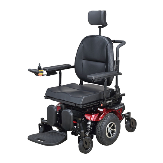
- Page 1 ��merits www.me.rltsusa.com Vision Ultra HD )P331 Seating System...
- Page 3 Welcome aboard your new rehab seat and thank you for choosing our product. Please read this manual carefully and follow all instructions before attempting to operate your rehab seat for the first time. If there is anything in this manual that you do not understand, or if you require additional assistance for setting up your rehab seat , please contact your local dealer.
- Page 4 The R Series Positioning System for Powered Wheelchair use the Merits Model P331 Power Wheelchair as the base unit for the tilting and reclining system. The Positioning System and base unit is to be sold together. Model P331 Powered Wheelchair is battery powered, center wheel motor driven and is controlled by the PG power wheelchair controller.
- Page 5 Indications For Use • ..The Merits Model R series Positioning System for Powered Wheelchair is intended for people using a powered wheelchair and requiring positional change. Its intended function and use is to aid in the pressure relief to persons confined to a powered wheelchair, by way of tilt and reclining seat -·...
- Page 6 owner's Manual Familiarize yourself with your rehab seat Feature Diagram ■ In this section, we will acquaint you with the many features of your rehab seat and how they work. Upon receipt of your rehab seat, inspect it for any damage. Your rehab seat consists of the following components.
- Page 8 owner's Manual ■ R-Series Positioning Seating System Specification Model Tilt Tilt, Recline(optional) Seat Width 18"~24" 18"-24" Dimension Depth 16"~20 16"~20 Height 22" 22" Seat Tilt Power Power Function Manual 90•~110• Recline Power Elevate Actuator DC Linear motor DC Linear motor Power...
- Page 9 ■ Terminology Joystick: The device used to "move" the powerbase wheelchair and " adjust" rehab seat. Controller: The device that allow joysticks to function. Not all joysticks have a n integral controller. Armrests: Where arms can rest during time spent on powerbase wheelchair. Footrest: Where feet rest during time spent on the powerbase wheelchair.
- Page 10 owner's Manual ■ Armrest Adjustment (1 )Angle adjustment Loosen the screw with the Allen key then move the armrest pivot ass'y, up and down to desired position, then tighten the screw. (Fig B 1) Fig B1 (2)Height adjustment (a)Loosen the lever to remove the side panel.
- Page 11 There are four stages for user to adjust, 8", 9", 10", 11".(Fig B2-4) (c)Remove the screw with Allen key then move the armrest ass'y. up and down to desired position, then reinstall and tighten the screw.(Fig B 2-4) (d)Loosen the screw with the Allen key then move the armrest pivot up and down to Fig B2-4 desired position, then tighten the screw.
- Page 12 owner's Manual ■ Joystick Adjustment Adjustment of the joystick position Swing back controller bracket. (Fig C1) Fig C1 (1) Use Allen key to loosen both screws, then move controller bracket forward and backward to desired position, tretighten screws and lock armrest brace in receiver.
- Page 13 ■ Seat Width Adjustment (1) Remove the cushion ass'y Fig D1 (2) Remove seat cushion ass'y Fig D2 (3) Lift the back cover -· Fig D3 Fig D4...
- Page 14 owner's Manual (6) Use an Allen key and an open-end wrench to remove the back panel screws and remove the back plate (Fig 04, Fig 05). Fig 05 (7) Use an Allen key to remove the seat-board screws, and then remove the seat-board.
- Page 15 (10) The width between the right and left backrest tubes sets can be adjusted according to the move of the adjust-side-tubes. (11) Reverse the above processes ( Fig 09 - Fig 01) then we can assemble the parts back. Attention: the shift distance of the left adjust-side-tube and the right adjust-side-tube have to the same.
- Page 16 owner's Manual (?)Use an Allen key and an open-end wrench to remove the screws and the nuts from the actuator lower bracket tube. (Fig D12) Fig D12 (8) Use an Allen key to remove the screws of the adjust-side-tubes on the seat base ass'y.
- Page 17 ■ Seat Depth Adjustment (1) Remove seat cu s h i on ass'y (Fig D2) (2) Remove seat-frame cover (Fig D3) (3) Use an Allen key to remove the seat-board screw, and then remove the seat-board (Fig D6) (4) Use an Allen key to remove the screws and nuts of the backrest (left and right), and then move front-rear directions to the appropriate position, then put the screws back in and lock...
- Page 18 owner's Manual ■ Seat Height Adjustment (1) Remove the seat-frame cover (2) Unplug the controller connectors Fig E1 (3) Unplug the main cable connectors Fig E2 -· (6) Use an Allen key to remove the seat 1:1, ... -· assy screws (4 locations) Fig E4...
- Page 19 (8) Both workers were required for seat removal from both left side and right side of the seat. (Fig ES) (9) Both workers should lift up the seat at the same time to remove the seat from the power chair and place it on the ground. (Fig ES) Fig ES (10) Remove the frame cover (Fig ES)
- Page 20 owner's Manual ■ Backrest Angle Adjustment: (1) Remove the cushion.(Fig P1) Fig P1 (2) Remove the seat cushion.(Fig P2) Fig P2 (3) Remove the back cover.(Fig P3) Fig P3 -· (4) Use the tool to loosen 10 screws. (Fig P4) 1:1, ...
- Page 21 ■ Backrest Angle Adjustment: (6) Hold the backrest use the tool to loosen screw and nut at the another side. (Fig P6) Fig P6 (7) Please refer the photo to adjust the backrest angle in your desired position. (Fig P7) Fig P7 •...
- Page 22 owner's Manual ■ Safety Switch (1 )Tilt In order to prevent user from dangerous driving, there is a "safety switch" to control the angle of rehab seat. ° When the seat tilts more than 15 , the drive function is disabled. °...
- Page 23 ■ Front Riggings & SAFTY WARGING Once the final adjustments are complete, with the user in standard driving position, ensure there is a between the bottom of the footplate (as shown in the table below) and the driving surface. To accomplish this may be necessary to raise the Seat to Floor Height which is adjustable in 1"...
- Page 24 owner's Manual (3)Height adjustment (a) Loosen and remove the screw, then move footplate support tube up and down to desired position, then reinstall and tighten screw. (Fig G4) FigG4 (4) Flip-up the footplate (a) Flip-up the f o otplate f o r easy access.
- Page 25 • Adjustment Legrest (1 )Swing in/out legrest (a) Pull the plastic lever down to release the locking mechanism. (Fig H1) (b) Push the leg rest outward (or inward). (Fig H1) (c) Push the legrest inward (or outward) until it locks into place. (Fig H1) Fig H1 (2)Elevating legrest (a) Pull up the legrest directly to the...
- Page 26 owner's Manual (4 )Height adjustment {a) Loosen the screw with screwdriver and wrench then take off the screw and nut (Fig H4) (b) Adjust the height of footplate to desired position then install the screw. (Fig H4) (c) Tighten the screw. (Fig H4) Fig H4 •...
- Page 27 (1 )Installing the high-pivot power elevating legrests onto the rehab seat. (a) Insert the top mounting pin of the elevating legrest from the side into the mounting tube on the chair. (Fig J1 ) (b) Swing the elevating legrest toward the center until it locks into position.
- Page 28 owner's Manual ( 4 )Height adjustment (a) Loosen the screw with screwdriver and wrench then take off the screw and nut (Fig J4) (b) Adjust the height of footplate to desired position then install the screw. (Fig J4) (c) Tighten the screw. (Fig J4) Fig J4 ■...
- Page 29 (c)lnsert the pin.(Fig K3) Fig K3 (d)lnsert and tighten the screws.(Fig K4) Fig K4 (f) Plug the acturator connector.(Fig K5) 1:1, Fig K5 (2) Height adjustment (a) Loosen and remove the screws, then move footplate support set up and down to desired position, then reinstall and tighten screws.(Fig L 1) Fig L 1...
- Page 30 owner's Manual (3) Flip-up the footplate (a) Flip-up the footplate for easy access. (Fig G5) (b) With an Allen key, simply turn the bolt clockwise to increase the angle or counterclockwise to decrease it. (Fig G5) (c) Hold hexagonal bolt(RH) with wrench and loosen the unit(LH). (Fig G5) (d) Choose the right angle and tighten the bolt.
- Page 31 Operating Your Captain Seat & Pan Seat(Optional) ■ Seat Removal (Captain Seat/ Pan Seat) Fi g 01 Fi g 02 Fi g 03 "II • Fi g 04 1111...
- Page 32 owner's Manual Fig 05 Fig 06 Fig 07 (1 )Loosen the knob and pull out the pin then remove the footplate. (Fig 01, Fig 02 and Fig 03) (2)Disconnect the controller plug.(Fig 04) (3)Turn backrest angle adjustment lever up, tilt backrest forward. (Fig 05) (4)Push down the lock-bar with left hand and lift the seat by right hand.
- Page 33 ■ Seat Installation (1 )Lift the seat vertically and insert the hook into the front trapeze bar. (2)Tilt the seat to horizontal position, then locking shaft of seat will be inserted directly into the locking device of the powerbase. (Fig 07 -> Fig 01 ) ■...
- Page 34 owner's Manual ■ Backrest Angle Adjustment: Turn backrest angle adjustment lever up, and till the backrest forward. (Fig P1) Fig P1 ■ Armrest Width/Height Adjustment: Fig P2 Fig P3 (1 )Width adjustment. (Fig P2) Loosen the set screw with alien key and adjust to the right width, then tighten the set screw.
- Page 35 ■ Headrest Height Adjustment: Depress then release the clamp on the left of backrest while pulling headrest up or pushing down until you reach the desired comfort position (one of three). (Fig P5) Fig P5 ■ Joystick Position Adjustment: Loosen the set screw with alley key and adjust the joystic bar to right position.
- Page 36 owner's Manual ■ Footplate The footplate is installed directly on the seating system to accommodate users who require a positioning system. (1) Installing the footplate onto the rehab seat Type I: (a) Insert the footplate into the mounting tube on the chair.(Fig Q1) Fig Q1 (b) Insert the pin and tighten the knob.
- Page 37 (3)Height adjustment (a) Loosen the remove the screw and nut, then move footplate support tube up and down to desired position, then reinstall and tighten screw. (Fig Q4) FigQ4 (4) Flip-up the footplate (a) Flip-up the footplate for easy access. (Fig Q5) (b) With an Allen key, simply turn the bolt clockwise to increase the angle or counterclockwise to decrease it.
- Page 38 owner's Manual ► ◄ Warranty Limited Warranty Corporation warrants to the original purchaser of this rehab seat that it is free of defect in material and workmanship and that , when operated within the guidelines and restrictions of this manual, will remain so free of defect in material and workmanship for a period of 18 months from the original date of purchase.
- Page 39 ► ◄ Warranty Registration WARRANTY REGISTRATION MODEL NO. SERIAL NO. -------------------- ----------------- DATE PURCHASED ---------------------- NAME --------------------- ADDRESS CI TY STATE ------- ------ ------ DEALER NAME STAMP RETURN ADDRESS...
- Page 40 owner's Manual TROUBlESHOOTING TIPS If your rehab seat is not operating properly, please take the following steps prior to calling Technical Support. Load-test Batteries-See Figure 1 1. Attach Battery Load-tester to battery. Observe polarity: Red is Positive-Black is Negative 2. Hold load switch on for 10 seconds.
- Page 42 owner's Manual...
- Page 43 We wish you a safe and comfortable riding experience!
- Page 44 Merits Health Products, Inc. www.meritsusa.com 4245 Evans Ave, Fort Myers, FL 33901 1-239-772-0579 | 1-800-963-7487 Fax: 1-239-574-2661 © Merits Health Products, Inc. Rv1.21-12...
Need help?
Do you have a question about the Vision Ultra HD P331 and is the answer not in the manual?
Questions and answers
What is the correct way to recharge batteries on vision ultra hd / tilt p331
To recharge the batteries on the Merits Vision Ultra HD P331, connect the charger to the charging port and plug it into a power outlet. The charger will begin charging the batteries automatically. Let the batteries charge fully before disconnecting.
This answer is automatically generated