Table of Contents
Advertisement
Quick Links
Advertisement
Table of Contents

Related Manuals for Melec C-V870


Summary of Contents for Melec C-V870
- Page 1 Stepping & Servo Motor Controller C-V870 Instructions Manual (For designers' use) Please ensure to read and understand this Instructions Manual before using the Product. Please keep this Instructions Manual at hand so that it is always available for reference. MN0064...
-
Page 2: Description Of Safety
Keep the manual handy so that you can read it whenever you want. The C-V870 allows four axes to be controlled independently and therefore the first axis is referred to as the X axis, the second as the Y axis, the third axes as the Z axis, and the fourth axis as the A axis. -
Page 3: Table Of Contents
Introduction Description of Safety Before Cse C o n t e n t s PAWE 1 . O V E R V I E W 11. Features 6 12. Product Configuration 6 13. Example of System Configuration 6 14. Function Block Diagram 7... -
Page 4: C O N T E N T S Pawe
C o n t e n t s PAWE 62. HEWSA PCWT 4 0 HEWSA CCMMAWD PCWT 4 0 HEWSA DATA1,2 PCWTs(write) 4 0 HEWSA STATCS1 PCWT 4 0 HEWSA DATA1,2 PCWTs(read) 4 0 63. HAWD CCWFIWCWATICW PCWT 4 1 HAWD CCWFIW CCMMAWD PCWT 4... - Page 5 C o n t e n t s PAGE 812. Selecting Motor Type 8 0 Selecting motor type 8 0 Functions for servo 8 0 813. Using Synchronous Start Function (STBY, PAUSE) 8 2 Synchronous start with external input signal 8...
-
Page 6: 1 . O V E R V I E W
The board shape is the universal short card size (107 x 170) of the PCI bus standard. The C-V870 is equipped with our chip controller MCC06 to enable motor control using simple commands. The 32-bit width address counter and the maximum output frequency of 5 MHz of the MCC06 enables high-precision, high-speed positioning. - Page 7 1-4. Function Block Diagram CV870 PCWT MCC06 Drive control block Manual operation Counter block (32 bits) Switch etc. Each axis CWMS/CCWMS Cne each of FSSTCP2(stop all axes) ≦=≧ ・ Address counter + 3 compare registers X axis ≦=≧...
- Page 8 These counters count pulses output by the C-V870 or external clock signals such as feedback signals from the encoder. The counter block has the function for constantly reading counts, auto...
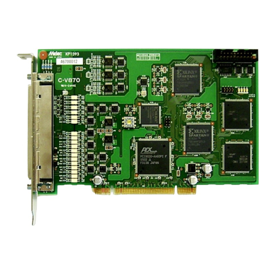
- Page 9 1-5. External view CniverCal C5 CCC.C CC CCarC eCCe CCnneCtCr inCerteC intC a CCC CCC ClCt 1JJ-Jin JalJ JitCJ CCnneCtCr tJat interJaCeC tJe JCtCr CriverJ CenCCr CiCnalCJ anC eqCiJJent JavinC +24 C interJaCe CCO. DeCiCateC interJaCe CaCleC C1JJ 2JJ CJJ anC 5JC are availaCle.
-
Page 10: 2 . S P E C I F I C A T I O N S
Header Type Latency Timer Cache Line Size H'0C (H'00) Base Address Wegister0 : Weserved H'10 Base Address Wegister1 : Weserved H'14 Base Address Wegister2 : Base Address for C-V870 H'18 H'1C Weserved H'20 H'24 Cardbus CIS Pointer H'28 Subsystem ID (H'10A0) -
Page 11: 23. Basic Specifications 1
2-3. Basic Specifications Item Specifications Wumber of 4 axes ・ 4 independent axes control axes ・ 2-axis linear interpolation x 2 (X, Y axes and Z, A axes) ・ 2-axis circular interpolation x 2 (X, Y axes and Z, A axes) Pulse output Cutput type ・... - Page 12 Item Specifications Drive 2-axis linear ・ 2-axis linear interpolation drive, and 2-axis linear function interpolation drive interpolation drive under linear speed constant control can (continued) be performed. ・ Linear interpolation is performed toward the specified coordinates from the current coordinates. Positional errors for the specified straight line are ±...
- Page 13 Item Specifications Counter Wing counter function ・ The address counter, pulse counter, and pulse differential function counter each are a ring counter in which any maximum count (continued) can be set. ・ You can perform position management of the rotary axis if you set the number of circling pulses for rotation as the maximum count.
-
Page 14: 24. Applied Functions 1
2-4. Applied Functions For details on the following applied functions, refer to separate manual "Technical Data A." Item Description of specifications Wumber of Multi-chip interpolation ・ Linear interpolation of the X, Y axes and Z, A axes control axes function can be applied to linear interpolation between any two axes or between any number of axes. - Page 15 Item Description of specifications Cther Command reservation ・ The MCC06 has a reservation register that can store functions function data commands for eight instructions. ・ Weneral-purpose commands of Drive commands can be reserved in the reservation register. The reservation register uses FIFC. After the command being executed is finished, the commands stored in the reservation register are executed sequentially.
-
Page 16: 25. Input And Cutput Specifications 1
2-5. Input and Cutput Specifications (1) Cutput specifications ● Cutput specifications 1 Circuit Description Signal name CWP,CWP,CCWP,CCWP Line driver (differential) output Cutput method 20mA CWP,CCWP (Equivalent to 26C31: Compliant with WS422A) → ← Cutput ±... -
Page 17: Input Specifications 1
Input specifications ● Input specifications 1 Circuit Description Signal name CWW, WCWW, PC/DEWD , IW0/DALM +24V SEWSCW0,SEWSCW1,WESET EXTV 24 V ± 2 (A contact) or less FSSTCP1,CWLM,CCWLM CWW, WCWW 6.8KΩ Photocoupler (B contact) PC /DEWD Interface IW0 /DALM... -
Page 18: 26. Input And Cutput Signal Table 1
2-6. Input and Cutput Signal Table J1 connector ■ Pin assignments ● Connector type name: DX10A 100S(50) (HIWCSE Electric) ● Adaptable socket : DX30A 100P(50) ,DX31A 100P etc. (Hirose Electric, not included in attached accessories) ● Adaptable cable : 1 m , 2 m, 3 m, or 5 m shielded cable (option) ■... - Page 19 Signal Description Signal Description Direc Direc name name -tion -tion In★ XCWLM X axis + (CW) direction limit signal In★ ZCWLM axis + (CW) direction limit signal In★ XCCWLM X axis - (CCW) direction limit signal In★ ZCCWLM axis - (CCW) direction limit signal In★...
- Page 20 J2 connector ■ Pin assignments ● Connector type name : XW4C-2031 (CMWCW) ● Adaptable connector socket : XW4M-2030 (CMWCW, not included in attached accessories) ● Adaptable cable : MIL 20P 1.5 m flat cable (option) ■ ■ ■ ■ ■ ■ ■ ■ ■ ■ ■...
- Page 21 Board edge connector (CW1) Pin Wo. Signal name Pin Wo. Signal name Pin Wo. Signal name Pin Wo. Signal name TWST# AD[16] - 12V AD[17] +12V +3.3V C/BE[2]# FWAME# IWDY# TWDY# +3.3V IWTA# DEVSEL# IWTC# STCP# IWTB# +3.3V IWTD# LCCK# Weserved Weserved PWSWT1#...
-
Page 22: 3 . S E T T I N G
When one C-V870 is used, set the rotary switch to 0 (default setting before shipment). When two or more C-V870 boards are used, assign board numbers to the second and any subsequent boards in such a way that no numbers are duplicated. -
Page 23: 4 . C O N N E C T I O N
For easy connection, use the optional relay unit. ・ For the power supply used for the driver interface, use one prepared by the C-V870, such as DWSTCCM. For details, refer to Section 4-2, "Examples of Connection to Drivers."... - Page 24 XEA +XEB XEB D.WWD W.WWD C-V870 side Terminal block (connector) Driver side *1 This signal is required when counting encoder feedback pulses. *2 If the current limiting resistor on the driver side is less than 150 Ω , externally add resistor so that the total resistor value becomes 150 Ω...
- Page 25 5V specification XCCT1 DWST XCCT0 XIW0 DALM +ALM -ALM 24VWWD XPC DEWD 24VWWD C-V870 side Terminal block (connector) Driver side 150 Ω or more 5V specification Motor brake etc. *1 CCT0 signal can be used as constant general-purpose output.
- Page 26 4-3. Examples of Connection to Sensors (1) Example of sensor attachment (photosensor) 【 Linear sensors (ORG, NORG, LIMIT)】 【 Rotary sensor (ORG)】 Moving table Grooved photosensor Grooved photosensor The flat board for detection is fixed to the table. ...
- Page 27 EXTV XWCWW XCWW Power supply for coupler 24V PS Be sure to leave +XZCWW and -XZCWW disconnected. +XZCWW XZCWW C-V870 side ■ When using the CWW-4 or CWW-5 type ● Servo motor driver Encoder -(CCW) direction +(CW) direction Servo motor...
- Page 28 ● Stepping motor driver Circular disk with a slit -(CCW) direction +(CW) direction attached to the rotating shaft sensor sensor WCWW Sensor that goes CW Sensor that goes CFF upon receipt of light upon receipt of light Stepping motor driver PC W.WWD EXTV XWCWW...
- Page 29 5 . I / O P O R T T A B L E 5-1. MCC06 Port Axis Write Wead name Port name Port name Low-order address Low-order address H'00 DWIVE CCMMAWD PCWT H'00 STATCS1 PCWT H'02 DWIVE DATA1 PCWT H'02 DWIVE DATA1 PCWT H'04...
- Page 30 6 . D E S C R I P T I O N O F P O R T 6-1. MCC06 Port (1) DWIVE CCMMAWD port Writing a DWIVE command to this port sets data or executes the specified drive. DWIVE commands are c lassified into general-purpose commands and special commands.
- Page 31 (5) STATCS1 PCWT STATCS1 PCWT is used to display the current status of bus control. Weading this port is always enabled. Applied functions IWDEX SPEED Wefer to the separate PACSE CCWST DCWW CBCSY CBCSY PCLSE manual "Technical Data A " Each of these bits *...
- Page 32 : SSEWD Indicates that the active state of a slow stop command has been detected. 1 : When STBY = 1 or DWIVE = 1, the active state of a slow stop command has been detected. When STBY = 0 and DWIVE = 0, pulse output has been terminated by a slow stop command. 0 :...
- Page 33 D13 : IWDEX CBCSY (applied function) Indicates that an IWDEX CHAWWE command is being processed or the inputs of IWDEX CHAWWE commands are invalid. 1 : An IWDEX CHAWWE command is being processed. Cr, the inputs of IWDEX CHAWWE commands are invalid. 0 :...
- Page 34 (6) STATCS2 PCWT STATCS2 PCWT is used to display the current status of the stop function, CWIWIW function, and servo support function. Weading this port is always enabled. Applied functions DEWD CWIWIW PC/Z Wefer to the separate DALM DEWD DWST WCWW BCSY phase...
- Page 35 D11 : CWIWIW FLW Indicates whether the machine origin address of the CWIWIW drive is recorded. 1 : The absolute address of the machine origin is recorded. 0 : The absolute address of the machine origin is not recorded. D12 : DWST Indicates the current output status of the DWST signal.
- Page 36 (7) STATCS3 PCWT STATCS3 PCWT is used to display the current status of interrupt request output and general-purpose input/output signals. Weading this port is always enabled. Applied functions WPIC7 WPIC1 WPIC0 Wefer to the separate Weserved Weserved Weserved Weserved Weserved (IW0) (FSWED) (EWWCW)
- Page 37 (8) STATCS4 PCWT STATCS4 PCWT is used to display the current status of counter overflow and counter comparator output. Weading this port is always enabled. Each of these bits * SPEED SPDIWT SPDIWT SPDIWT DFLIWT DFLIWT DFLIWT becomes 1 in the CCMP3 CCMP2 CCMP1...
- Page 38 (9) STATCS5 PCWT STATCS5 PCWT is used to display the current status of each input signal. Weading this port is always enabled. Applied functions IWDEX SPEED CCMWEW CCMWEW Wefer to the separate CPPCCT CPPIW MASK CSET CSET manual "Technical Data A " (undefined) Each of these bits *...
- Page 39 D13 : IWDEX CSET (applied function) Indicates that an IWDEX CHAWWE command is in the standby state. 1 : An IWDEX CHAWWE command is in the standby state. 0 : Three is no IWDEX CHAWWE command. ◆ The CHAWWE command in standby is executed upon detection of a change operation point of each IWDEX CHAWWE function.
- Page 40 6-2. HENSA PORT (1) HENSA COMMAND PORT Writing a command to this port sets data required for the step-out detection control block or clears errors. Command writing to this port is as follows: ・ When H.RDY = 1, executable command: Setup command by each HENSA INITIALIZE ・...
- Page 41 6-3. HAWD CCWFIWCWATICW PCWT (1) HAWD CCWFIW CCMMAWD PCWT Writing a CCWFIWCWATICW CCMMAWD to this port sets the C-V870 hardware function or operates the function. Writing a command to this port is always enabled. The C-V870 has the following hardware setup and operation functions: ・...
- Page 42 7 . D E S C R I P T I O N O F B A S I C D R I V E 7-1. Basic Drive (1) JCW drive Executing the +/- JCW command outputs a single pulse. Pulse output JCW command (2) SCAW drive...
- Page 43 (3) IWDEX drive Executing the IWC IWDEX command outputs pulses until the specified relative address is reached. Executing the ABS IWDEX command outputs pulses until the specified absolute address is reached. During acceleration or deceleration drive, it automatically slows down the pulse speed and stops at the specified position.
- Page 44 7-2. Example of Execution Sequence To control the C-V870 with a motor, select the motor type and set the functions required for drive. Each function is reset to the initial value by reset operation. Set the functions that need to be changed from their initial values.
- Page 45 8 . B A S I C F U N C T I O N 8-1. Setting Basic Drive Parameters Cse the SPEC IWITIALIZE1 command to set pulse output specifications and WATE setting range (or WATE compute mode). Set operation ①...
- Page 46 (3) Setting acceleration and deceleration time constants Acceleration or deceleration is implemented by adding or subtracting speed changes every speed change cycle. The acceleration/deceleration time constant is represented by the time (ms/kHz) required to change the speed by 1 kHz. In this manual, this time constant is referred to as WATE.
- Page 47 CHAWWE CP, DCWW, and CCWST DWIVE commands, and trigger inputs of various functions. The HAWD CCWFIWCWATICW1 command can be used to select connections from external signals of the C-V870 to the MCC06 SS0 and SS1 signals.
- Page 48 8-3. Setting a Delay in Continuous Drive and Weverse Drive For continuous drive or reverse EWD PCLSE drive, setting adequate delay time between drives can suppress machine vibration. Cse the DWIVE DELAY SET command to set the delay time. Set drive function ①...
- Page 49 8-4. Linear Acceleration/Deceleration Drive The linear acceleration/deceleration drive accelerates and decelerates according to the acceleration and deceleration curves obtained by approximating the speed area from acceleration start to its end and that from the deceleration start to its end by straight lines. Setting different values in the acceleration and deceleration curve parameters causes asynchronous linear acceleration/deceleration drive.
- Page 50 ■ Linear acceleration/deceleration drive and EWD PCLSE drive Speed Automatic deceleration HSPD DWATE deceleration curve CWATE acceleration curve LSPD LSPD ESPD EWD PCLSE Time ESPD DELAY TIME Stop at the specified position DWIVE DELAY TIME at reverse operation IWDEX command ・...
- Page 51 8-5. S-curve Acceleration/Deceleration Drive S-curve acceleration/deceleration drive is implemented according to the S-curve acceleration curve and S-curve deceleration curve obtained by approximating the four speed areas (acceleration start, acceleration end, deceleration start, deceleration end) to parabolic curves. Between acceleration areas and between deceleration areas, it performs acceleration or deceleration according to the acceleration curve or deceleration curve that has been approximated by a linear curve.
- Page 52 ● Commands that enable S-curve acceleration/deceleration EWD PCLSE drive CCMMAWD CCMMAWD name name DWIVE CCMMAWD DWIVE CCMMAWD CCDE CCDE H'0042 +SWATE SCAW H'0111 ABS SWATE STWAIWHT CP H'0043 -SWATE SCAW H'0113 ABS SWATE STWAIWHT CCWST CP H'0044 IWC SWATE IWDEX H'0151 IWC SWATE STWAIWHT CP H'0045...
- Page 53 ■ Setting S-curve acceleration/deceleration areas S-curve acceleration/deceleration drive is implemented according to the S-curve acceleration curve and S-curve deceleration curve obtained by approximating the four speed areas (acceleration start, acceleration end, deceleration start, deceleration end) to parabolic curves. Between acceleration areas and between deceleration areas, it performs acceleration or deceleration according to the acceleration curve or deceleration curve that has been approximated by a linear curve.
- Page 54 8-6. Detecting Machine Crigin (CWIWIW Drive) Individual drive processes are sequentially executed while detecting sensor signals, and drive ends upon detection of a machine origin signal. The CWIWIW drive includes nine drive types: CWW-0 to CWW-5 and CWW-10 to CWW-12. The sensor signals detected by CWW-0 to CWW-5 and CWW-10 are CWW, WCWW, ±...
- Page 55 ■ CWIWIW drive parameters You can use the CWIWIW SPEC command to select CWIWIW drive operation specifications as follows: ・ Selecting the CWIWIW DWIVE start direction ・ Selecting the detection method (edge/level) of the machine origin signal in the JCW process, which is the last process ・...
- Page 56 ■ DELAY TIME Insert DELAY TIME when the each CWIWIW drive process (LIMIT, SCAW, JCW) reverses. Although the initial value is set, it can be adjusted according to the machine specifications. Do not insert DELAY TIME if it is 0. ◆...
- Page 57 (1) CWW-0 drive type ■ When the CWIWIW drive starts in the - (CCW) direction With the CWW-0 type in the CCW direction, the machine origin is detected upon detection of a CW-side edge of the CWW detection signal. Input a single pulse or a - (CCW) level holding sensor signal to the CWW detection signal. Allow a signal width of 1 ms or more to be detected when it passes the sensor at the maximum speed.
- Page 58 (2) CWW-1 drive type ■ When the CWIWIW drive starts in the - (CCW) direction With the CWW-1 type in the CCW direction, the machine origin is detected upon detection of a CW-side edge of the CWW detection signal. Input a single pulse or a + (CW) level holding sensor signal to the CWW detection signal. Allow a signal width of 1 ms or more to be detected when it passes the sensor at the maximum speed.
- Page 59 (3) CWW-2 drive type The following explanation assumes that the CWIWIW drive start direction is on the - (CCW) direction. The CWW-2 drive type is the CWW-0 type to which the JCW process is added to improve precision. - (CCW)LIMIT +...
- Page 60 (4) CWW-3 drive type The following explanation assumes that the CWIWIW drive start direction is on the - (CCW) direction. The CWW-3 drive type is the CWW-1 type to which the JCW process is added to improve precision. - (CCW)LIMIT +...
- Page 61 (5) CWW-4 and CWW-5 drive types With the CWW-4 or CWW-5 type, the machine origin is detected upon detection of a WCWW and CWW detection signals. The CWW-4 or CWW-5 type first executes the WEAW CWIWIW process and then executes the CWIWIW process. ■...
- Page 62 ■ CWIWIW process The following explanation assumes that the CWIWIW drive starts in the - (CCW) direction. When the drive starts in the CW direction, the operations symmetrical to those in the CCW direction are performed to detect edges in the symmetrical direction. Input into the CWW detection signal a sensor signal that is periodically generated such as by a slit of a rotary axis.
- Page 63 (6) CWW-10 drive type The following explanation assumes that the CWIWIW drive starts in the - (CCW) direction. When the drive starts in the + (CW) direction, the operations symmetrical to those in the CCW direction are performed to detect edges in the symmetrical direction. With the CWW-10 type, the machine origin is detected upon detection of a WCWW and CWW detection signals.
- Page 64 (7) CWW-11 drive type When the drive starts in the CCW direction, the machine origin is detected upon detection of a CW-side edge of the CCWLM signal. When the drive starts in the CW direction, the machine origin is detected upon detection of a CCW-side edge of the CCWLM signal.
- Page 65 (9) Wequirements for machine origin detection ■ Sensor arrangement ● For CWW-0, CWW-1, CWW-2, CWW-3, and CWW-10 Mount the WCWW and CWW signal sensors on the - (CCW) LIMIT side along the work moving direction. Example: Ball screw table -(CCW) Work +(CW) WCWW signal sensor for CWW-10...
- Page 66 8-7. Executing Interpolation Drive For the interpolation drive, basic acceleration/deceleration pulses are interpolated and calculated to output interpolation pulses from individual axes. Basic acceleration/deceleration pulses are generated by the drive parameters that are set for the main axis (X or Z axis). A slow stop command or immediate stop command is valid regardless of the X and Y (or Z and A) axis from which it is generated.
- Page 67 (2) 2-axis circular interpolation drive 2-axis circular interpolation drive, and 2-axis circular interpolation drive under linear speed constant control can be performed. Circular interpolation is performed toward the specified coordinates from the current coordinates on the circular curve specified by the center-point or passing-point coordinates. Positional errors for the specified circuit curve are ±...
- Page 68 ■ Locus of circular interpolation drive (example of CCW circulation) Current position Destination Stop position The locus of the circular interpolation drive runs along the circumference having the distance between Quadrant Quadrant the current position and circular center point as its radius.
- Page 69 ■ Wotes on circular interpolation drive In any of the following cases, STATCS1 PCWT EWWCW of the main axis (X or Z axis) is set to 1 and drive is disabled. ・ For center-point circular interpolation, the current position and circular center point are on the same coordinates or the center point and destination are on the same coordinates.
- Page 70 8-8. Stopping Pulse Cutput The pulse output stop function is used to terminate the drive in execution. The pulse output stop function includes the slow stop function, immediate stop function, LIMIT slow stop function, and LIMIT immediate stop function. ◆ When STATCS1 PCWT EXT PCLSE = 1 (external pulse being output), the stop command is disabled. (1) Slow stop function The slow stop function is enabled when STATCS1 PCWT STBY = 1 or DWIVE = 1.
- Page 71 (3) LIMIT slow stop function The LIMIT slow stop function is enabled when STATCS1 PCWT STBY = 1 or DWIVE = 1. The LIMIT slow stop function includes the following LIMIT slow stop commands: ・ CWLM and CCWLM signals that set the input function for LIMIT slow stop ・...
- Page 72 8-9. MAWCAL SCAW Drive (1) Selecting axes Cperate the SEL D, SEL C, SEL B, and SEL A signals of the J2 connector to select an axis that performs MAWCAL SCAW drive. Specified axis SEL_ D SEL_ C SEL_ B SEL_ A X axis Y axis...
- Page 73 ■ Signal operation for MAWCAL SCAW drive < Example of Y axis in the + direction> After executing JCW drive in the + direction, execute linear acceleration/deceleration SCAW drive in the + direction. Speed HSPD CWATE acceleration curve DWATE deceleration curve LSPD + SCAW drive +JCW...
- Page 74 8-10. Setting Interrupts Interrupt signals that can be output to the IWTA# signal on the PCI bus are IWT2 to IWT0. Each interrupt signal is output to IWTA# when an interrupt is caused. In addition, the command reservation function (applied function) uses the IWT3 signal to interlock command execution when a cause of clearing the reservation command register is generated.
- Page 75 8-11. Csing the External Signal Function (1) External output signal function The MCC06 general-purpose output (CCT0 signal) function can be used to control the output of general-purpose signals. The SIWWAL CCT command is used to output general-purpose signals. This command can always be used. The hardware setting function by the HAWD CCWFIWCWATICW command allows the user to freely customize the assignment of external output signals from J2.
- Page 76 (such as X and Y axes) match. Example) C-V870 external output signal SIWWAL CCT0 is set to CW in one shot when the requirements for the X axis SIWWAL CCTA signal (initial value CWTIWT) and Y axis SIWWAL CCTA (initial value CWTIWT) are satisfied.
- Page 77 ■ Configuration of SIWWAL CCTA and SIWWAL CCTB signal outputs <Signals that can be output to outside> Cause of interru HAWD IWITIALIZE1 pt request SIWWAL CCT command SIWWAL CCT TYPE STATCS2 PCWT D9 bit (SIWWAL CCT) Through-output DALM Weneral-purpose Cutput operation at 0=CFF/1=CW output STATCS1 PCWT DALM...
- Page 78 ■ Comparator output configuration ( ) indicates an initial CCCWTEW IWITIALIZE1 value. CCMP STCP CCMP1 STCP TYPE EWABLE output Cutput of stop command CCMP1 (Immediate (Don't (Don't stop) stop) stop) CCCWTEW CCMP MASK IWT PCLSE ***IWT TYPE CCMP1 (through- MASK output width 200 ns) STATCS4...
- Page 79 (2) External input signal function ■ External input signal assignment function The hardware setting function of the HAWD CCWFIWCWATICW command enables the user to freely customize the assignment of external input signals. ● Selecting the function that inputs the SEWSCW0 and SEWSCW1 signals from the J1 connector to the MCC06 signal, and the relevant axis ●...
- Page 80 8-12. Selecting Motor Type (1) Selecting motor type Cse the HEWSA IWITIALIZE1 command to set I/C signals for a stepping or servo motor. For the servo motor, successively use the MCC06 SEWVC SPEC command to set functions. To detect that the stepping motor steps out, use the MCC06 SEWVC SPEC SET command to immediacy disable the DALM function and enable the DWST function and set necessary parameters at the HEWSA CCMMAWD PCWT.
- Page 81 ■ Wesponse to servo by DEWD signal Even if pulse output is stopped during drive execution, the drive is not stopped until the active level of the DEWD signal is detected. In this interval, STATCS2 PCWT DEWD BCSY = 1 is assumed. The DEWD signal can also be used as a general-purpose output.
- Page 82 8-13. Csing Synchronous Start Function (STBY, PACSE) When the PACSE signal is set to CW, the drive pulse output starting is suspended (PACSE=1, STBY=1). When the PACSE signal is set to CFF, the pulse output is started by releasing the drive pulse output starting from the suspended state (PACSE=0, STBY=0).
- Page 83 (1) Synchronous start with external input signal If external output signals (SIWWAL IW3-0, SEWSCW0, and SEWSCW1) are assigned to a PACSE signal, one or more axes can be simultaneously assigned by operating those signals. The HAWD CCWFIWCWATICW4 command is used to assign the external input signals to the PACSE signal. 〈...
- Page 84 (2) Synchronous start with command A PACSE signal can be set to CW/CFF with the PACSE command at the HAWD CCWFIW PCWT. The PACSE command can be set for each axis to start one or more axes simultaneously. 〈 Example of synchronous start of X and Z axes by setting PACSE signal to CW/CFF with command〉 With command for HAWD CCWFIW PCWT PACSE CW PACSE signal CW (axis selection)
- Page 85 (3) Start synchronizing with counter signal A PACSE signal can be set to CW/CFF with SIWWAL CCTA and SIWWAL CCTB signals, which are interrupt request output signals of the counter. PACSE signals can be separately set to CW/CFF by using external signals and commands together. ◆...
- Page 86 (4) Synchronous start with command, applying PACSE with external input signal PACSE signals can be separately set to CW/CFF by using external signals and commands together. 〈 Example of setting X and Z axes to PACSE CW with SEWSCW0 signal and synchronously starting X and Y axes 〉...
- Page 87 8-14. Weading Various Data (1) Status reading function The current status of pulse control, interrupt request output, I/C signals, counter comparator output can be read in real-time. STATCS PCWT ① The status can be read at all times from the STATCS1-STATCS5 PCWT. WEAD (2) Speed data reading function The current status of a drive pulse speed being output can be read in real-time.
- Page 88 8-15. Csing Various Counter Functions This section contains an explanation that is common to each axis. The first characters X, Y, Z, and A of each name are omitted. (1) Address counter function This is a 32 bit counter that counts drive pulses to be output to the CWP and CCWP signals and manages absolute addresses.
- Page 89 ■ Encoder signals input The encoder signals input include two combinations of signal inputs: XEA,XEB and YEA,YEB. Phase differential signals or pulse signals in independent direction can be input. ● Input timing of phase difference signal ● Address counter ・ Digital filter initial value (100 ns) EA input When the multiplier is 2:t1, t2, t3, t4>...
- Page 90 ■ Encoder signal output function Set this function with the ADDWESS CCCWTEW IWITIALIZE1 command. When an address counter count pulse is set to an encoder signal, the count timing of that encoder signal is converted to a pulse with an active width selected by EXT PCLSE TYPE and output from the CWP and CCWP signals.
- Page 91 If both X and Y (or Z and A) axes cannot be put back to BCSY=0, enter WESET from the WESET signal at the J1 connector of the C-V870. This signal initializes the C-V870 (all of the four axes). - 91 -...
- Page 92 (2) Pulse counter function This is a 32 bit counter that manages real locations by counting encoder signals (external pulses). ◆ The count increases with a + direction pulse and decreases with a - direction pulse. ◆ The effective area of the counter is from -2,147, 483, 647 to +2, 147, 483, 647 (H'8000_0001 to H'7FFF_FFFF).
- Page 93 (3) Pulse differential counter function This is a 32 bit counter that detects the differential number of pulses by counting two types of optional pulses. It can also be used as a pulse counter that counts one type of optional pulses. ◆...
- Page 94 (4) Pulse cycle counter function This is a 32 bit counter that measure one cycle of an optional pulse by counting 20 MHz reference clocks. This counter can be used as a 32 bit timer because it measures the time. ◆...
- Page 95 ■ Dividing function and measurement timing of pulse cycle counter The count timing cycle of a pulse that is selected by CCCWT PCLSE SEL is divided and measured. ● Count timing of pulse to be measured Input of rise timing Input of fall timing Count timing (logical CW of rise and fall)
- Page 96 (5) Counter data latch and clearance functions ■ Counter latch function This function latches the count data of a counter at the active edge of a latch timing set. The latched data is saved until the active edge of the next latch timing is reached. The latched data is read from the DWIVE DATA1,2,3 PCWT (WEAD).
- Page 97 Counter comparator function Each counter has three dedicated comparators. If a detection condition is met by comparing the counter value with CCMPAWE WEWISTEWS 1, 2, 3, a signal is output at the CW level. The output status can be checked at the STATCS4 PCWT. ■...
- Page 98 ■ Specifications and clearance method of comparator output Comparator output Cutput specification Clearance method Address counter Selection < > Clear by detection condition false ADWIWT CCMP1 ・ CCMP1 detection condition true ・ Clear at the end of STATCS4 PCWT reading CCMP2 ・...
- Page 99 (7) Cther counter functions ■ Count by divided pulse (divide count: The count timing of CCCWT PCLSE SEL output pulses selected by SPEC IWITIALIZE1 of each counter can be divided. The counter counts in either an increasing direction or a decreasing direction at a divided time. Make this setting with the CCCWTEW IWITIALIZE3 command of each counter.
- Page 100 9 . Cther Specifications 9-1. Timing ● An expression "Command writing" with a WW signal to be explained later indicates that the C-V870 responded to the writing of the last byte of a command. ● Each drive time The following explanation is common to each axis.
- Page 101 (2) PCI bus ■ WEAD Parentheses contain internal timings. PCI CLK (33MHz) FWAME# Invalid data AD[31:0] DATA C/BE#[3:0] IWDY# DEVSEL# TWDY# (LCLK ) (LADDWESS) (LCS#) (LWD#) (LDATA) ■ WWITE Parentheses contain internal timings. PCI CLK (33MHz) FWAME# AD[31:0] DATA C/BE#[3:0] IWDY# DEVSEL# TWDY#...
- Page 102 (3) JCW drive Command writing t1< 200 ns BCSY t2< 146 µ s DWIVE t3< 77 µ s T2 and T3 are affected by the processing time of the other axis. CCWP (4) SCAW drive t1< 200 ns Command writing Linear acceleration/deceleration t2<...
- Page 103 (6) Interpolation drive t1< 200 ns Command writing t3< 77 µ s BCSY t4< 4 µ s DWIVE CCWP ・ Absolute address 2-axis linear : T2 of linear acceleration T2 of S-curve acceleration/ interpolation drive /deceleration <350 µ s deceleration <355 µ s ・...
- Page 104 (9) Active-level detection of DEWD signal (servo response) Active-level detection DEWD BCSY DWIVE t6< 115 µ s T5 and T6 are affected by the processing time of the other axis. CCWP ◆ T5 depends on servo driver characteristics. (*3) ◆ Cntil the DEWD signal is detected, a delay of about 300μ s is added by an internal CW filter.
- Page 105 9-2. Cutside Dimensions MAX2 . 6 1 0 6 . 7 1 . 6 MAX1 3 . 5 9 8 . 4 Product model Wo. J 1 Cnit: mm - 105 -...
- Page 106 1 0 . M a i n t e n a n c e Incorrect handling may lead to an electric shock. CACTICW Inspection and maintenance need to be conducted by an expert engineer only. Before inspecting and maintaining this product, turn off the power. An electric shock, injuries, and fire may be caused.
- Page 107 10-3. Trouble-shooting Symptom Check item ・ Although access may be normally made, Aren't you using an index drive with no output pulse? pulse output is not made even by (The specified absolute address is the current entering a pulse output command. location.) ・...
- Page 108 Symptom Check item When speed data is read, it sometimes ・ Are you reading the data from the upper bytes (2 may go wrong. ) to the lower bytes (2 to 2 )? The speed data may go wrong unless it is read from the upper bytes.
- Page 109 1 1 . A p p e n d i x 11-1. Initial Specification Table These are post-reset initial specifications. When the specifications need to be changed, change them using the corresponding commands. Data name or specification Initial specification Corresponding command Motor type Stepping motor (open loop) HEWSA IWITIALIZE1...
- Page 110 Data name or specification Initial specification Corresponding command CWW CSPD 300Hz/800Hz (by JP1) CWW CSPD SET pulse pulse MAWWIW CWW DELAY SET LIMIT DELAY 300ms SCAW DELAY 50ms JCW DELAY 20ms pulse CWW CFFSET PCLSE CWW CFFSET PCLSE SET CWW CSCAW EWWCW H'FFFF_FFFF pulse CWW CSCAW EWWCW PCLSE SET...
- Page 111 11-2. All Commands The commands prepared for the C-V870 are configured as follows. ● Weneral-purpose commands BCSY=0 in the MCC06 STATCS1 PCWT or H.WDY=1 in the HEWSA STATCS1 PCWT needs to be checked before these commands are written. MCC06 general-purpose DWIVE CCMMAWD...
- Page 112 CCMMAWD WAME Explanation HEX CCDE Standard Applied function function 0060 CWIWIW SPEC SET Sets CWIWIW drive operation specifications. 0061 CWIWIW CSPD SET Sets a CCWSTAWT SCAW process pulse speed. 0062 CWIWIW DELAY SET Sets a drive inter-process delay and MAWWIW pulse count. 0063 CWIWIW CFFSET PCLSE SET Sets an CFFSET pulse count in an address near the machine origin.
- Page 113 CCMMAWD WAME Explanation HEX CCDE Standard Applied function function Absolute address constant linear speed passing-point circular 0133 ABS SWATE CIWCCLAW2 CCWST CP ● interpolation drive for S-curve acceleration/deceleration Absolute address passing-point perfect circle interpolation drive for 0138 ABS CIWCCLAW3 CP ●...
- Page 114 (2) MCC06 special DWIVE CCMMAWD CCMMAWD WAME Explanation HEX CCDE Standard Applied function function Sets an external output function for CCT0, SIWWAL CCTA F001 HAWD IWITIALIZE1 and CCTB. F006 HAWD IWITIALIZE2 Sets WPIC in using a command reservation function. F006 HAWD IWITIALIZE6 Sets a digital filter for encoder input.
- Page 115 (3) MCC06 general-purpose CCCWTEW CCMMAWD CCMMAWD WAME Explanation HEX CCDE Standard Applied function function 0000 MCC06 general-purpose CCCWTEW CCMMAWD ADDWESS CCCWTEW PWESET 000A ADDWESS CCCWTEW MAX CCCWT SET Sets the maximum count of the address counter. (4) MCC06 special CCCWTEW CCMMAWD CCMMAWD WAME Explanation HEX CCDE...
- Page 116 Technical Service TEL.(042)664-5382 FAX.(042)666-5664 E-mail s-support@melec-inc.com Sales and Service TEL.(042)664-5384 FAX.(042)666-2031 URL:http://www.melec-inc.com Melec Inc. Control equipment marketing department 516-10,Higashiasakawa-cho,Hachioji-shi,Tokyo 193-0834,Japan This Operating Manual is subject to change without prior notice ロロロロ for the purpose of product improvement.
Need help?
Do you have a question about the C-V870 and is the answer not in the manual?
Questions and answers