Table of Contents
Advertisement
Quick Links
FUSION
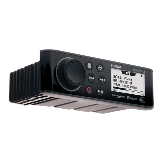
MS-RA70NSX
®
INSTALLATION INSTRUCTIONS
Important Safety Information
WARNING
See the Important Safety and Product Information guide in the product box for product warnings and other
important information.
This device must be installed according to these instructions.
Before applying power to this product, make sure it has been correctly grounded according to these
instructions.
CAUTION
To avoid possible personal injury, always wear safety goggles, ear protection, and a dust mask when drilling,
cutting, or sanding.
NOTICE
Do not use the stereo as a template when drilling the mounting holes because this may damage the glass
display and void the warranty. You must only use the included template to correctly drill the mounting holes.
You must read all installation instructions before beginning the installation. If you experience difficulty during
the installation, contact Fusion Product Support.
What's In the Box
• DIN mounting plate
• Four 8-gauge, self-tapping screws
• Power and speaker wiring harness
• Auxiliary-in, line-out, and subwoofer-out wiring harness
Tools Needed
• Phillips screwdriver
• Electric drill
• Drill bit (size varies based on surface material and screws used)
• Rotary cutting tool or jigsaw
• Silicone-based marine sealant (optional)
October 2022
GUID-DA740304-7C70-417A-8779-630F09652A74 v3
Advertisement
Table of Contents

Related Manuals for Garmin FUSION MS-RA70NSX


Summary of Contents for Garmin FUSION MS-RA70NSX
- Page 1 FUSION MS-RA70NSX ® INSTALLATION INSTRUCTIONS Important Safety Information WARNING See the Important Safety and Product Information guide in the product box for product warnings and other important information. This device must be installed according to these instructions. Before applying power to this product, make sure it has been correctly grounded according to these instructions.
-
Page 2: Mounting Considerations
Mounting Considerations • The stereo can be mounted on a flat surface or in a single-DIN opening as a replacement for an existing stereo. • The stereo must be mounted in a location that allows open airflow around the rear of the stereo for heat ventilation. - Page 3 Mounting the Stereo in a New Location NOTICE Be careful when cutting the hole to mount the stereo. There is only a small amount of clearance between the case and the mounting holes, and cutting the hole too large could compromise the stability of the stereo after it is mounted.
-
Page 4: Connection Considerations
13 Place the stereo in the cutout. 14 Secure the stereo to the mounting surface using the included screws 15 Snap the screw covers in place Replacing an Existing Stereo 1 Remove and disconnect the existing stereo. 2 If necessary, remove the existing wiring harness or install a vehicle- or vessel-specific wiring-harness adapter (not included) to provide access to the power and speaker wiring. -
Page 5: Port Identification
Port Identification Item Description Connects the stereo to a typical AM/FM antenna using an RF coaxial connector. If you are installing the stereo on a boat with a metal hull, you must use a ground-dependent antenna, and if you are installing the stereo on a boat with a non-metal hull, you must use a ground-independent antenna. - Page 6 Wiring Harness Wire and Connector Identification...
- Page 7 Wire Color/ Wire Function Notes Number Red (yellow Connects to the positive terminal of a 12 Vdc power source Power (+) on some wire capable of supplying 15 A. harnesses) Connects to the negative terminal of a 12 Vdc power source capable of supplying 15 A. This wire should be connected before Ground (-) Black connecting the red (or yellow) wire.
-
Page 8: Connecting To Power
Connecting to Power When connecting the stereo to power, you should connect it through the ignition or another manual switch. If it is necessary to extend the power and ground wires, use 14 AWG (2.08 mm ) wire. For extensions longer than 1 m (3 ft.), use 12 AWG (3.31 mm ) wire. - Page 9 Single-Zone System Wiring Example Speakers Water-tight connection Complete System Wiring...
- Page 10 Item Description Zone 2 speakers Water-tight connection Powered amplifier Zone 2 line out Amplifier-on signal wire Zone 1 speakers Zone 1 line out Zone 1 subwoofer out Each cable provides a single mono output to a powered subwoofer or subwoofer amplifier, and one or both cables can be used, depending on the connection requirements of the subwoofer or amplifier.
- Page 11 NMEA 2000 System Wiring Diagram NOTE: NMEA 2000 is available on Fusion MS-RA70NSX models only. Stereo Supported chartplotter MFD or compatible Fusion NMEA 2000 remote control In-line switch NMEA 2000 power cable NMEA 2000 drop cable from the stereo, up to 6 m (20 ft.) NMEA 2000 drop cable from the chartplotter MFD or compatible Fusion NMEA 2000 remote control 9 to 16 Vdc power supply...
- Page 12 Stereo Information Specifications General Weight 556 g (19.6 oz.) Water resistance IEC 60529 IPX7 (front), IEC 60529 IPX3 (rear) Operating temperature range From 0 to 50°C (from 32 to 122°F) Storage temperature range From -20 to 70°C (from -4 to 158°F) Input voltage From 10.8 to 16 Vdc Current (max.) 15 A...
- Page 13 Stereo Dimension Drawings Front Dimensions 188 mm (7.40 in.) 60 mm (2.36 in.) Side Dimensions 23.5 mm (0.93 in.) 100 mm (3.94 in.) 50 mm (1.97 in.)
-
Page 14: Software Updates
Garmin. Bluetooth word mark and logos are owned by the Bluetooth SIG, Inc. and any use of such marks by Garmin is under license. NMEA , NMEA 2000 , and the NMEA 2000 ®...
Need help?
Do you have a question about the FUSION MS-RA70NSX and is the answer not in the manual?
Questions and answers