Table of Contents
Advertisement
Quick Links
Advertisement
Chapters
Table of Contents

Subscribe to Our Youtube Channel
Related Manuals for NF ZA57630


Summary of Contents for NF ZA57630
- Page 1 IMPEDANCE ANALYZER ZA57630 INSTRUCTION MANUAL (BASICS) NF Corporation...
- Page 3 DA00068820-003 IMPEDANCE ANALYZER ZA57630 INSTRUCTION MANUAL (BASICS)
- Page 4 Registered Trademarks National Instruments, LabVIEW, and Measurement Studio are registered trademarks of National Instruments Corporation in the United States. WINDOWS® EMBEDDED 8.1 INDUSTRY PRO Used with permission from Microsoft. Other company names and product names used in this instruction manual may be trademarks or registered trademarks of their respective companies.
- Page 5 ■ The scope of this Manual This manual describes the ZA57630 that conform to requirements of CE marking. Products without CE marking affixed, may not meet directives for CE marking (EMC and others).
-
Page 6: Introduction
Read this chapter for a quick overall understanding of the panel and its use. 4. Basic operation This chapter explains the basic operating procedures of the ZA57630. Refer to this chapter as you use this instrument. 5. Specifications This chapter describes this instrument specifications (functions and performance). - Page 7 ──── Safety Precautions ──── For safe use of this product, give full attention to the following warnings and cautions. The NF Corporation shall not be held liable for damages that arise from failure to observe these warnings and cautions. This product is a Class I device (with protective conductor terminal) that conforms to the IEC insulation standards.
- Page 8 Safety Precautions Do not modify this product. Never modify this product in any way. Modification might create new risks. The NF Corporation may refuse to service an instrument that has an unauthorized modification. Do not expose this product to water.
- Page 9 This device is equipped with a lithium battery. Use the services of an industrial waste disposal contractor to dispose of such batteries. b) The LCD backlight module that is used in this product does not contain mercury. c) Use the services of an industrial waste disposal contractor for disposal of the entire product. ZA57630...
-
Page 10: Table Of Contents
5.5 Measurement Connectors (Measurement Mode IMPD−2T) ........... 5-11 5.6 Measurement Connectors (Measurement Mode G−PH) ..........5-14 5.7 Measured Signal Control Section ................... 5-18 5.8 Measurement Accuracy ....................5-20 5.9 Measurement Processing Section .................. 5-31 5.10 Display Section ......................5-35 ZA57630... - Page 11 Contents 5.11 Memory ........................5-36 5.12 External Memory ......................5-36 5.13 External Input/Output Function ..................5-37 5.14 Miscellaneous Specifications ..................5-39 ZA57630...
- Page 12 Figure 3-25 List Operations (Immediate Settings) ..............3-27 Figure 3-26 Palette Operations (Immediate Settings) ............. 3-27 Figure 3-27 Text Settings (Immediate Settings) ..............3-28 Figure 3-28 Switching Text Input Palette ................. 3-29 Figure 3-29 Execution Operations (Requiring Confirmation) ........... 3-30 viii ZA57630...
- Page 13 Figure 4-5 How to Check Operation Using 100 Ω RESISTOR (IMPD−3T) ........ 4-10 Figure 4-6 Impedance Measurement Connection Example 5 (IMPD−2T) ......... 4-11 Figure 4-7 Gain and Phase Measurement Connection Example ..........4-12 Figure 5-1 External dimensions ....................5-40 ZA57630...
- Page 14 Table 4-3 Graph Axis Parameters (Measurement Mode: IMPD−EXT / IMPD−3T / IMPD−2T) ... 4-21 Table 4-4 Graph Axis Parameters (Measurement Mode: G−PH) ..........4-22 Table 4-5 Display Parameter Conversion Formulas (Measurement Mode: IMPD−EXT / IMPD−3T / IMPD−2T) ........4-23 Table 4-6 Display Parameter Conversion Formulas (Measurement Mode: G−PH) ....4-24 ZA57630...
- Page 15 1. Introduction Features ................1-2 Applications ................. 1-3 Operating Principle .............. 1-4 1.3.1 Operating Principle ............1-4 1.3.2 Measurement Modes ............. 1-6 ZA57630...
-
Page 16: Features
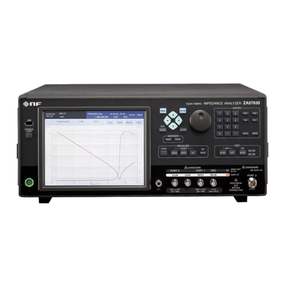
1.1 Features 1.1 Features The “ZA57630 IMPEDANCE ANALYZER” is an impedance analyzer with a maximum frequency of 36 MHz, maximum signal amplitude of 3 Vrms, maximum DC bias of ±40 V, and maximum sweep speed of 0.5 ms/point. It has a high basic accuracy of 0.08 % and is capable... -
Page 17: Applications
● Measurement of the impedance characteristics of electrolytes, dielectric materials, and solutions at micro voltage and current levels by using a high sensitivity voltage preamplifier and current-voltage conversion amplifier. ZA57630... -
Page 18: Operating Principle
1.3 Operating Principle 1.3.1 Operating Principle The ZA57630 applies a sine wave signal from an internal measurement signal source to the device under test (DUT). It then detects current I flowing through the DUT and voltage V applied to the DUT, performs discrete Fourier transform (DFT), and calculates impedance Z (= V/I) of each analysis frequency component from the obtained Fourier coefficient obtained through the DFT. - Page 19 It converts between the communication protocols of the GPIB, USB, RS-232, and LAN general interfaces and the internal communication protocol of UI CPU CKT. The USB-B connector is located on the rear panel and is used for connecting with a PC to control this instrument. ZA57630...
- Page 20 The connector to use for measurement differs depending on the measurement mode setting. ・IMPD−EXT,IMPD−3T,G−PH :H /OSC, H /PORT1, L /PORT2 ・IMPD−2T :PORT3 ○ Connection example for measurement mode IMPD−EXT ZA57630 PORT3 DUT drive amplifier / OSC Voltage probe / PORT1 / PORT2 Current probe ○ Connection example for measurement mode IMPD−3T...
- Page 21 1.3 Operating Principle ○ Connection example for measurement mode IMPD−2T ZA57630 PORT3 / OSC / PORT1 / PORT2 ○ Connection example for measurement mode G−PH ZA57630 PORT3 Equipment under test (EUT) / OSC / PORT1 / PORT2 ZA57630...
- Page 22 (Blank) ZA57630...
-
Page 23: Preparation Before Use
2. Preparation before Use Checking before Use ............2-2 Assembly and Installation ............ 2-4 2.2.1 General Precautions for Installation ......2-4 2.2.2 Installation Conditions ..........2-4 2.2.3 Rack Mounting ............. 2-5 Grounding and Power Supply Connection ......2-10 Simple Operation Check ........... 2-12 Calibration ................. -
Page 24: Checking Before Use
When you have removed the contents from the cardboard box, check them. If you find a scratch on the product or an accessory is missing, report the problem to NF Corporation or its authorized agent. - Page 25 2.1 Checking before Use ■ Options / related products ○ Test fixtures and test leads Test fixtures and test leads are not included. Please purchase them separately. The major test fixtures and test leads that can be used in combination with this instrument are as follows.
-
Page 26: Assembly And Installation
・This instrument uses forced air cooling by fan. If you notice that the fan is stopped, turn off the power immediately and then contact NF Corporation or its authorized agent. If you continue to use this instrument with the fan stopped, there is a risk of the expansion of damages and hence difficulty/impossibility of repair. -
Page 27: Rack Mounting
2.2 Assembly and Installation 2.2.3 Rack Mounting This instrument can be mounted in a 19-inch IEC rack, EIA standard rack, or JIS standard rack by attaching a rack mount kit (sold separately). Rack mount kits for a milli rack (JIS) and inch rack (EIA) are available. -
Page 28: Figure 2-1 Rack Mount Kit Assembly Drawing (Jis)
2.2 Assembly and Installation Figure 2-1 Rack Mount Kit Assembly Drawing (JIS) ZA 57630... -
Page 29: Figure 2-2 Rack Mount Kit Assembly Drawing (Eia)
2.2 Assembly and Installation Figure 2-2 Rack Mount Kit Assembly Drawing (EIA) ZA 57630... -
Page 30: Figure 2-3 Rack Mount Dimensions (Jis)
2.2 Assembly and Installation Figure 2-3 Rack Mount Dimensions (JIS) ZA 57630... -
Page 31: Figure 2-4 Rack Mount Dimensions (Eia)
2.2 Assembly and Installation Figure 2-4 Rack Mount Dimensions (EIA) ZA 57630... -
Page 32: Grounding And Power Supply Connection
If the power outlet voltage is greater than 125 V AC or you want to use the product in a foreign country, consult with NF Corporation or its authorized agent. When turning the power off and then back on, wait at least 1 minute before turning the power back on. - Page 33 2.3 Grounding and Power Supply Connection ! WARNING To ensure that the power cord can be disconnected from the inlet of this instrument, provide sufficient space around the inlet, and to ensure that the power plug can be disconnected from the outlet, use an outlet in an easily accessible location and provide sufficient space around the outlet.
-
Page 34: Simple Operation Check
Tap [OK]. 3. Attach the included CALIBRATION BOX to the H to L connectors on the front panel. ZA57630 CALIBRATION BOX (accessory) 4. Execute self-calibration. Tap [Calibration] in top menu 2/3. Select [Calibration] – [CALIBRATION] and then tap the [EXEC] function key. -
Page 35: Calibration
The performance test should be carried out by a person who is familiar with measuring instrument specifications and who has general knowledge regarding measuring instruments. If the performance test results do not satisfy the specifications, NF Corporation will perform adjustment or calibration to restore the original performance. If calibration or adjustment is required, contact NF Corporation or its authorized agent. - Page 36 (Blank) 2-14 ZA 57630...
-
Page 37: Panel Operations
3. Panel Operations Functions and Operations of Panel Parts ......3-2 Input and Output Connectors ..........3-8 Overview of the Operation Screens ........3-19 Operation Tree ..............3-32 Setting Screen Reference ..........3-42 Initial Settings ..............3-111 ZA 57630... -
Page 38: Functions And Operations Of Panel Parts
3.1 Functions and Operations of Panel Parts 3.1 Functions and Operations of Panel Parts This section provides an overview of the part names, functions, and operations of the front and rear panels. 3.1.1 Front Panel LCD (touch panel input) Measurement Marker Measurement Displays the setting menus and... -
Page 39: Figure 3-2 Rear Panel
3.1 Functions and Operations of Panel Parts 3.1.2 Rear Panel Power inlet The center pin is for the protective ground terminal. GPIB connector VGA connector Be sure to perform grounding. exhaust USB connector LAN connector vent POWER switch RS-232 connector Nomenclature Certification 10MHz REF IN... - Page 40 3.1 Functions and Operations of Panel Parts 3.1.3 Descriptions of the Screens and Keys This instrument can be operated with the front panel keys and LCD touch panel. Most operations can be performed using either of them. The input devices are always available so they can be used together to perform operations.
- Page 41 3.1 Functions and Operations of Panel Parts 3.1.4 Explanation of Front Panel Keys ● Menu operation keys and knob : This displays the top menu on the LCD. Pressing this key displays or ・MENU hides the menu. For details, refer to “■ Menu” in “3.3.1 Menu Operating Procedures”.
- Page 42 3.1 Functions and Operations of Panel Parts : This switches the data trace indicated by the active marker. ・TRACE Each press of the button switches the data trace indicated by the active marker in the order of MEAS → REF1 → ... → REF8 → MEAS. : This switches the active marker.
- Page 43 3.1 Functions and Operations of Panel Parts ● Measurement signal controls : This turns the outputs off. The AC lamp and DC lamp both go out. ・AC/DC OFF : This turns only the AC output off. Only the AC lamp goes out. ・AC OFF : This turns the outputs on.
-
Page 44: Input And Output Connectors
3.2 Input and Output Connectors 3.2 Input and Output Connectors The connector to use for measurement differs as follows depending on the measurement mode setting. Measurement mode Connector to use IMPD−EXT, IMPD−3T, G−PH : L /PORT2, H /PORT1, H /OSC IMPD−2T : PORT3 For the L... -
Page 45: Figure 3-4 Functions Of Measurement Connectors (Measurement Mode: Impd−3T)
3.2 Input and Output Connectors Connector : BNC connector Output amplitude : Max. 3 Vrms DC bias : Max. ±5 V (However, it is restricted to a maximum of ±5 V along with the measurement signal amplitude.) Output impedance : 50 Ω (nominal value) ■... -
Page 46: Figure 3-5 Functions Of Measurement Connectors (Measurement Mode: Impd−2T)
3.2 Input and Output Connectors When using HV DC bias ±40 V Maximum driving current 60 mArms (depends on the measurement range, frequency etc.) Output impedance : 50 Ω (When HV DC bias is used, approximately 1 kΩ at approximately 100 Hz or less.) ■... -
Page 47: Figure 3-6 Function Of Dc Bias Out Connector
3.2 Input and Output Connectors Maximum driving current : 60 mArms (depends on the measurement range, frequency etc.) Output impedance : 50 Ω (When HV DC bias is used, approximately 1 kΩ at approximately 100 Hz or less.) ■ Measurement connectors when power is off The measurement connectors are connected to the internal circuits even when the power is off. -
Page 48: Figure 3-7 Function Of 10 Mhz Ref In Connector
3.2 Input and Output Connectors Output voltage setting is a voltage at no load (open load). When a 600 Ω load is connected, a voltage that is half of the set value is output. ■ Connectors when power is off When the power is off, the relay is also off and the output amplifier is separated from the DC BIAS OUT connector on the rear panel. -
Page 49: Figure 3-8 Function Of 10 Mhz Ref Out Connector
3.2 Input and Output Connectors 3.2.6 10 MHz REF OUT This connector outputs the clock signal that is actually used as the reference clock by this instrument. When this instrument is operating with an external 10 MHz reference clock (input to 10 MHz REF IN), the frequency that is output is the same as that of the external reference clock. -
Page 50: Figure 3-9 Handler Interface Connector Pin Assignment Diagram
3.2 Input and Output Connectors 3.2.7 HANDLER INTERFACE The comparator results can be output into the handler interface connector on the rear panel of this instrument. Connecting to the part handler allows an auto part sorting system to be configured. For details on the comparator, refer to “1.15.1 Comparator”... - Page 51 3.2 Input and Output Connectors Table 3-2 Handler Interface Signal Functions Pin No. Signal name Description External trigger signal (rising edge). TRIG, /TRIG Can be switched to falling edge. /RCL0 (LSB) Setting/correction memory selection signal /RCL1 (binary) If the trigger signal of pin no.1 is received /RCL2 when /RCL-VALID is the low level and trigger /RCL3...
- Page 52 3.2 Input and Output Connectors External DC power input (common) Each signal of the handler interface is 21 to 25 EXT_COM isolated from the enclosure and operates with external DC power. 41 to 45 INT_DCV Internal DC power output (+5 V) Internal DC power output (common) This is connected to the enclosure.
-
Page 53: Figure 3-10 Equivalent Circuit Of Handler Interface
3.2 Input and Output Connectors ! CAUTION Do not apply a voltage more than 42 Vpk between the signals or common of the handler interface and the enclosure. There is a risk of damage to this instrument. ■ Handler interface I/O equivalent circuit EXT_DCV EXT_DCV EXT_DCV... -
Page 54: Figure 3-12 I/O Connector Equivalent Circuit Of Aux Connector
+24 V is output from pin 2 and -24 V is output from pin 10, but do not connect a device other than one specified by NF Corporation. If other than a specified device is connected, there is a risk that this product may become unstable. -
Page 55: Overview Of The Operation Screens
3.3 Overview of the Operation Screens 3.3 Overview of the Operation Screens 3.3.1 Menu Operating Procedures Most of the settings of this instrument can be configured by tap operation of the menus and dialog boxes (windows). This section describes the basic operations of the menus. The following figure shows an example of a screen without menus displayed. -
Page 56: Figure 3-15 Measurement Condition Display Area
3.3 Overview of the Operation Screens ・Measurement status : Self-calibration in progress IDLE : Stopped SPOT : Spot measurement in progress : Up sweep in progress DOWN : Down sweep in progress : Number of current measurement sequence : Total number of sequences In the single mode (when the REPEAT lamp on the front panel is off), this instrument enters the stopped (idle) state when measurement finishes. -
Page 57: Figure 3-16 Basic Menu Operation Area
3.3 Overview of the Operation Screens ■ Basic menu operation area Figure 3-16 Basic Menu Operation Area : This displays a shortcut menu for quickly accessing items for ・[SETUP] which settings are frequently changed on this instrument. This has the same function as the SETUP key on the front panel. : This displays the top menu on the LCD. - Page 58 3.3 Overview of the Operation Screens operating procedures and function details, refer to “3.5.6 Marker Menu” in this instruction manual and “1.7 Marker Operation” in Instruction Manual (Advanced). 3-22 ZA 57630...
-
Page 59: Figure 3-19 Menu Display Example
3.3 Overview of the Operation Screens ■ Menus Pressing the MENU key or tapping the [MENU] button displays a menu (refer to “Figure 3-19 Menu Display Example”). The menus have a hierarchical structure and the menu at the very top layer of the hierarchy is called the top menu. Menu Function keys Figure 3-19 Menu Display Example... -
Page 60: Figure 3-21 Menu Layer Operation
3.3 Overview of the Operation Screens ■ Menu Layer Navigation and Selection A menu with “>” after the menu name has another menu in a layer below. Tapping that button displays the menu of the layer below. To return to the menu of the layer above, tap the button at the top of the menu. A menu with a layer above has “<”... -
Page 61: Figure 3-23 Numerical Settings (Immediate Settings)
3.3 Overview of the Operation Screens ■ Numerical settings (immediate settings) When the function keys are displayed, tapping [MODIFY] enables modification of the parameters. Move to the digit you wish to modify with the left/right key or left/right button. The digit that can be modified is displayed highlighted. Use the up/down key, up/down button, or knob to increase or decrease the numerical value of the selected digit. -
Page 62: Figure 3-24 Numerical Settings
3.3 Overview of the Operation Screens ■ Numerical settings When the function keys are displayed, tapping [EDIT] displays the numerical input palette. Enter a numerical value in the ENTRY section on the front panel or the palette and press ENTER or tap [OK] to apply the setting. Clear the parameter. -
Page 63: Figure 3-26 Palette Operations (Immediate Settings)
3.3 Overview of the Operation Screens Figure 3-25 List Operations (Immediate Settings) ■ List operations (requiring confirmation) The procedure is the same as for “■ List operations (immediate settings)” above, but a setting confirmation dialog box is displayed at the end and the setting is not applied until you actually press ENTER or tap [OK]. -
Page 64: Figure 3-27 Text Settings (Immediate Settings)
3.3 Overview of the Operation Screens ■ Text settings (immediate settings) The procedure is the same as for “■ Numerical settings (immediate settings)” above, but alphabet letters and symbols can also be handled in addition to numerical values. When the function keys are displayed, tapping [EDIT] displays the text input palette. -
Page 65: Figure 3-28 Switching Text Input Palette
3.3 Overview of the Operation Screens If you tap the [SHIFT] button in the text input palette, the character set of the palette changes. Uppercase alphabet letter set Lowercase alphabet letter set Number and symbol set 1 Number and symbol set 2 Figure 3-28 Switching Text Input Palette 3-29 ZA 57630... -
Page 66: Figure 3-29 Execution Operations (Requiring Confirmation)
3.3 Overview of the Operation Screens ■ Execution operations (requiring confirmation) Tapping the target menu or function key displays an execution confirmation dialog box. The operation is executed if you tap [OK] and the operation is canceled if you tap [CANCEL] in the confirmation dialog box. - Page 67 3.3 Overview of the Operation Screens In the single display style, the vertical axis on the left side is called the Y1-axis and the vertical axis on the right side is called the Y2-axis. In the split display style, the vertical axis of the upper graph is called the Y1-axis, the vertical axis of the lower graph is called the Y2-axis, and the X-axis is common for both graphs.
-
Page 68: Operation Tree
3.4 Operation Tree 3.4 Operation Tree The following shows the operation tree for operating this instrument from the panel. For the descriptions of keys and screens, refer to “3.1 Functions and Operations of Panel Parts”. Front Panel : Displays/hides the menu. MENU key : Open a list of frequently set parameters. - Page 69 3.4 Operation Tree (Keypad) 0 to 9 , . key : Numerical and decimal point keys : Minus key − key : Exponent key (power of 10) EXP key : Backspace key BS key < , > key : Move the cursor. : Discard the setting.
- Page 70 3.4 Operation Tree : Set measurement. [Measure] : Set measurement item 1. [PRMTR1] : Set measurement item 2. [PRMTR2] : Set measurement item 3. [PRMTR3] : Set measurement item 4. [PRMTR4] : Set measurement item 5. [PRMTR5] : Set measurement item 6. [PRMTR6] : Set the measurement time.
- Page 71 3.4 Operation Tree : Set the graph. [Graph] : Set the graph title. [TITLE SET] : Set the X-axis item. [DISPLAY MODE X] : Set the Y-axis item. [DISPLAY MODE Y] : Select the data to display. [DISPLAY TRACE] : Set the display of measurement data. [MEAS] : Set the display of reference data 1.
- Page 72 3.4 Operation Tree : Set the markers. [Marker] : Set the active marker. [ACTIVE] : Search for a marker. [SEARCH] : Execute an X-axis search. : Execute a Y1-axis search. [Y1] : Execute a Y2-axis search. [Y2] : Execute a special search. [BW] : Set to search automatically when a sweep ends.
- Page 73 3.4 Operation Tree : Data trace [Trace] [MEAS TRACE COPY] : Measurement data : Copy to reference data. [REF TRACE] : Copy to equalizing data. [EQU CORR MEM] : Copy to open correction data. [OPEN CORR MEM] : Copy to short correction data. [SHORT CORR MEM] : Copy to load correction data.
- Page 74 3.4 Operation Tree : Set remote control. [Remote] : Select the interface. [INTERFACE] : Display the USB related parameters. [USB] : Set GPIB. [GPIB] : Set the address. [ADDRESS] [RS-232] : Set RS-232. : Set the baud rate. [BAUD RATE] : Set flow control.
- Page 75 3.4 Operation Tree : Error correction [Calibration] : Set open correction. [OPEN CORR] : Set short correction. [SHORT CORR] : Set load correction. [LOAD CORR] : Enable or disable. [FUNCTION] : Set the load standard value format. [LOAD STD FMT] : Set the load standard values.
- Page 76 3.4 Operation Tree : Various calculation functions [Calculate] : Estimate the equivalent circuit. [EQUIV CKT FITTING] : Select the equivalent circuit. [CKT TYPE] : Element value 1 [(prmtr1)] : Element value 2 [(prmtr2)] : Element value 3 [(prmtr3)] : Element value 4 [(prmtr4)] : Execute curve fit.
- Page 77 3.4 Operation Tree : Set the comparator. [Comparator] : Set BIN sorting / LIMIT comparison. [BIN] : Enable or disable. [FUNCTION] : Set the deviation mode. [DEVIATION TYPE] : Set the primary parameter reference value. [PRI REF] : Set the secondary parameter reference value. [SEC REF] : Set the BIN sorting value.
-
Page 78: Setting Screen Reference
3.5 Setting Screen Reference 3.5 Setting Screen Reference This section describes each setting screen. In the menu explanations that begin from the next page, the procedures for setting and changing parameters are presented in the formats shown below. <Numerical settings (immediate settings)> <Numerical settings (requiring confirmation)>... - Page 79 3.5 Setting Screen Reference 3.5.1 Mode Menu This menu sets the measurement mode of this instrument. ○ Setting procedure <List operations (requiring confirmation)> ・IMPD−EXT : Measure the impedance. Current-voltage conversion needs to be performed outside of this instrument. The OSC, PORT1, and PORT2 connectors are used. ・IMPD−3T : Measure the impedance.
- Page 80 3.5 Setting Screen Reference 3.5.2 OSC Menu ■ [FREQUENCY]: Set the frequency. This sets the frequency for performing spot measurement. ○ Setting procedure <Numerical settings (immediate settings)>, <Numerical settings> ○ Functions of function keys : Copy the sweep lower frequency limit to FREQUENCY. ・[SWEEP MIN ->...
- Page 81 3.5 Setting Screen Reference : Set with current (Arms, A). ・[A] ■ [AMPLITUDE]: Set the measurement signal amplitude. This sets the measurement signal amplitude for performing spot measurement. ○ Setting procedure <Numerical settings (immediate settings)>, <Numerical settings> ○ Functions of function keys : Copy the sweep lower amplitude limit to AMPLITUDE.
- Page 82 3.5 Setting Screen Reference *2: Displayed only in the IMPD−3T and IMPD−2T measurement modes. (Supplementary explanation) When the measurement mode is IMPD−3T and IMPD−2T, the operation when this is set to “ON” is in accordance with the “AMPLITUDE UNIT” setting for the amplitude unit (constant voltage operation with the voltage unit and constant current operation with the current unit).
- Page 83 3.5 Setting Screen Reference ■ [DC BIAS]: Set the DC bias. This sets the bias for performing spot measurement. ■ [DC BIAS]-[DC BIAS]: Set the DC bias. This sets the DC bias value. ○ Setting procedure <Numerical settings (immediate settings)>, <Numerical settings> ○...
- Page 84 3.5 Setting Screen Reference ■ [POWER AMP GAIN]: Set the DUT drive amplifier gain. This sets the DUT drive amplifier gain (amplification factor) for amplifying the signal output from the OSC connector. ○ Setting procedure <Numerical settings (immediate settings)>, <Numerical settings> The setting range is ±(1.00E-12 to 1.00E+12) and the setting resolution is 3 digits.
- Page 85 3.5 Setting Screen Reference : Turn measurement synchronous driving on. Only the AC output is ・SYNC(AC) turned on when measurement starts and only the AC output is turned off when measurement ends. DC on/off control is not performed. If repeat measurement is performed while measurement synchronous driving is on, the output is turned off each time for each measurement is completed for either spot measurement or sweep measurement.
- Page 86 3.5 Setting Screen Reference : Use an external reference clock if an external reference clock is available. ・ENABLE Even if ENABLE is set, the internal reference clock of this instrument will be used if an external reference clock is not detected or if the frequency differs from the specified frequency. The reference clock with which this instrument is currently operating is indicated by the status display in the upper part of the LCD screen.
- Page 87 3.5 Setting Screen Reference 3.5.3 Measure Menu ■ [PRMTR1] to [PRMTR6]: Set the spot measurement item. This sets the measurement item (display item) for spot measurement. ○ Setting procedure <Palette operations (immediate settings)> (Measurement modes: IMPD−EXT, IMPD−3T, and IMPD−2T) : Magnitude of impedance (Ω) ・Z : Phase of impedance (°) ・θ...
- Page 88 3.5 Setting Screen Reference : Imaginary part of relative permittivity (unitless number) ・ε : Dissipation factor of relative permittivity (unitless number) ・D ε : Relative permeability (unitless number) ・µ : Real part of relative permeability (unitless number) ・µ : Imaginary part of relative permeability (unitless number) ・µ...
- Page 89 3.5 Setting Screen Reference ○ Functions of function keys : Set the measurement time with the numerical input palette. ・[EDIT] ・[MODIFY] : Modify the measurement time with the knob or cursor keys. ■ [START DELAY]: Set the measurement start delay time. This sets the delay time for when sweep measurement starts and spot measurement starts.
- Page 90 3.5 Setting Screen Reference ■ [TRIGGER SOURCE]: Select the trigger source. This selects the measurement start (trigger) source. If this is not selected, a trigger from a trigger source will be disabled. ○ Setting procedure <List operations (immediate settings)> : The MEASURE START UP, DOWN, and SPOT keys on the front panel are ・PANEL trigger sources.
- Page 91 3.5 Setting Screen Reference 3.5.4 Sweep Menu ■ [SEQ SWEEP]: Set sequence measurement. This function performs measurements in the order set in the setting memory of this instrument. It allows, for example, dividing the sweep range to perform measurement with different conditions.
- Page 92 3.5 Setting Screen Reference ■ [SWEEP ITEM]: Set the sweep item. This selects the parameter to sweep. The parameter set here becomes the X-axis of the graph. ○ Setting procedure <List operations (immediate settings)> : Sweep the frequency. ・FREQUENCY : Sweep the measurement signal amplitude. ・AMPLITUDE : Sweep the DC bias.
- Page 93 3.5 Setting Screen Reference ■ [RESOLUTION]: Set the sweep resolution. This sets the sweep resolution. The number of data points obtained in a sweep measurement is the resolution value set here + 1. ○ Setting procedure <Numerical settings (immediate settings)>, <Numerical settings> The setting range is 3 to 2,000 and the setting resolution is 1.
- Page 94 3.5 Setting Screen Reference ■ [SLOW SWEEP]-[VARIATION]: Set the threshold value for the amount of change. This sets the threshold value for the amount of parameter change that is regarded as a sudden change. The value is stored internally for each parameter type that is set in [TYPE]. ○...
- Page 95 3.5 Setting Screen Reference ■ [RESONANT TRACK]-[UPPER FREQ]: Set the tracking frequency upper limit. ■ [RESONANT TRACK]-[LOWER FREQ]: Set the tracking frequency lower limit. This sets the frequency range for performing resonant frequency tracking. ○ Setting procedure <Numerical settings (immediate settings)>, <Numerical settings> ○...
- Page 96 3.5 Setting Screen Reference ■ [RESONANT TRACK]-[POLARITY]: Set the phase characteristic polarity of the DUT. This specifies the slope (polarity) of the DUT phase - frequency characteristic. ○ Setting procedure <List operations (immediate settings)> ・POSITIVE : Increase the phase as the frequency increases. ・NEGATIVE : Decrease the phase as the frequency increases.
- Page 97 3.5 Setting Screen Reference 3.5.5 Graph Menu ■ [TITLE SET]: Set the graph title. This sets the graph title. ○ Setting procedure <Text settings (requiring confirmation)>, <Text settings> Up to 63 characters can be entered. ○ Functions of function keys : Set the title with the text input palette.
- Page 98 3.5 Setting Screen Reference ■ [DISPLAY MODE X]: Set the X-axis format. This sets the format (type) of the X-axis. ○ Setting procedure <Palette operations (immediate settings)> There are formats that cannot be selected depending on the setting of the Y-axis format. For details, refer to “4.5 Setting Sweep Measurement”.
- Page 99 3.5 Setting Screen Reference : The Y1-axis is series inductance (H) and the Y2-axis is series resistance (Ω). −R ・L : The Y1-axis is series inductance (H) and the Y2-axis is quality coefficient −Q ・L (unitless number). : The Y1-axis is parallel inductance (H) and the Y2-axis is parallel resistance (Ω). ・L −R : The Y1-axis is parallel inductance (H) and the Y2-axis is quality coefficient...
- Page 100 3.5 Setting Screen Reference (All measurement modes) ・[Y1 LOG] : The Y1-axis is the logarithmic axis. ・[Y1 LIN] : The Y1-axis is the linear axis. ・[Y2 LOG] : The Y2-axis is the logarithmic axis. ・[Y2 LIN] : The Y2-axis is the linear axis. (Supplementary explanation) The V1, V2, V, and I measurement items are the voltage and current amplitude values measured by this instrument.
- Page 101 3.5 Setting Screen Reference ■ [SCALE RANGE]: Set the graph axis ranges. ■ [SCALE RANGE]-[X MAX]: Set the maximum X-axis value. ■ [SCALE RANGE]-[X MIN]: Set the minimum X-axis value. ■ [SCALE RANGE]-[Y1 MAX]: Set the maximum Y1-axis value. ■ [SCALE RANGE]-[Y1 MIN]: Set the minimum Y1-axis value. ■...
- Page 102 3.5 Setting Screen Reference ■ [GRID LINE STYLE]: Set the grid lines. This sets the grid line style. ○ Setting procedure <List operations (immediate settings)> ・BROKEN LINE : Display a broken-line grid. : Display a solid-line grid. ・SOLID LINE ■ [PHASE RANGE]: Set the phase display range. This sets the phase display range.
- Page 103 3.5 Setting Screen Reference ■ [PLOT COLOR]: Set the data trace colors. ■ [PLOT COLOR]-[MEAS Y1]: Set the color of Y1 of the measurement data. ■ [PLOT COLOR]-[MEAS Y2]: Set the color of Y2 of the measurement data. ■ [PLOT COLOR]-[REF1 Y1]: Set color of Y1 of reference data 1. ■...
- Page 104 3.5 Setting Screen Reference 3.5.6 Marker Menu ■ [ACTIVE]: Set the active marker. This specifies the active marker (move the focus by knob operation to specify the marker for which to display read values on the graph). ○ Setting procedure <Numerical settings (immediate settings)>, <Numerical settings>...
- Page 105 3.5 Setting Screen Reference ■ [SEARCH]-[X]: Execute an X-axis search. ○ Setting procedure <Execution operations (immediate execution)> ○ Functions of function keys (When the graph X-axis is SWEEP) : Move to the position at which the X value is the minimum. ・[X MIN] : Move to the position at which the X value is the maximum.
- Page 106 3.5 Setting Screen Reference : Move to the position of the next smaller X value of [Y1]. ・[PREV Y1] : Move to the position of the next larger X value of [Y1]. ・[NEXT Y1] : Move to the position where the difference from MARKER1 is ・[⊿...
- Page 107 3.5 Setting Screen Reference the Y2 value is the minimum. ・[PREV Y2 BOTTOM] : Move to the position of the next smaller Y2 value of [Y2 BOTTOM]. ・[NEXT Y2 BOTTOM] : Move to the position of the next larger Y2 value of [Y2 BOTTOM]. : Move to the position where the Y2 value is the maximal.
-
Page 108: Figure 3-25 List Operations (Immediate Settings)
3.5 Setting Screen Reference : Automatically search for the maximal Y2 value. ・Y2 PEAK ・Y2 BOTTOM : Automatically search for the minimal Y2 value. : Automatically search for the X value. ・X : Automatically search for the Y1 value. ・Y1 : Automatically search for the Y2 value. - Page 109 3.5 Setting Screen Reference : Display the marker as a normal marker. ・ON ■ [MARKERn]-[MODE]: Set the marker mode. : 2 to 8 This sets the display mode of markers 2 to 8. ○ Setting procedure <List operations (immediate settings)> : Hide the marker.
- Page 110 3.5 Setting Screen Reference 3.5.7 Trace Menu ■ [MEAS TRACE COPY]: Select the storage location for measurement data. This copies the measurement data (MEAS DATA). ■ [MEAS TRACE COPY]-[REF TRACE]: Copy to reference data. ○ Setting procedure <Execution operations (immediate execution)>, <Numerical settings (requiring confirmation)>, <Numerical settings>...
- Page 111 3.5 Setting Screen Reference ■ [MEAS TRACE COPY]-[OPEN_PEXT CORR MEM]: Copy to port extended end open correction data. ■ [MEAS TRACE COPY]-[SHORT_PEXT CORR MEM]: Copy to port extended end short correction data. ■ [MEAS TRACE COPY]-[LOAD_PEXT CORR MEM]: Copy to port extended end load correction data. This can be set only when the measurement mode is IMPD−EXT, IMPD−3T, and IMPD−2T.
- Page 112 3.5 Setting Screen Reference device or other external storage device if necessary. ○ Setting procedure <Execution operations (requiring confirmation)> ○ Functions of function keys : Delete the measurement data. ・[DELETE] ■ [DELETE REF]: Delete the reference data. This deletes the reference data (REF DATA) from memory. The graph traces are also deleted. The data cannot be recovered after deletion, so save the data to a USB memory device or other external storage device if necessary.
- Page 113 3.5 Setting Screen Reference measurement. ・Some measurement conditions are indicated as “NaN” (Not a Number) depending on the data. For example, MEASURE TIME is indicated as “NaN” for the data of equivalent circuit estimation results (refer to “1.11 Equivalent Circuit Estimation” in Instruction Manual (Advanced)).
- Page 114 3.5 Setting Screen Reference 3.5.8 Range Menu IMPD−EXT IMPD−3T G−PH IMPD−2T ■ [RANGE PORT1]: Set the port 1 measurement range. ■ [RANGE PORT2]: Set the port 2 measurement range. This sets the measurement range. (When measurement mode is IMPD−EXT and G−PH) ○...
- Page 115 3.5 Setting Screen Reference is the largest. ■ [OVER ACT BEEP]: Set the beep operation for over-level detection. This sets the beep operation for over-level detection. ○ Setting procedure <List operations (immediate settings)> : Sound a beep upon over-level detection. ・ON : Do not sound a beep upon over-level detection.
- Page 116 3.5 Setting Screen Reference 3.5.9 Storage Menu For details on operations, refer to “1.17 Memory Operations” in Instruction Manual (Advanced). ■ [CONDITION FILE]: Perform setting condition file operations. Perform operations such as saving and loading the setting information of this instrument. ■...
- Page 117 3.5 Setting Screen Reference ○ Setting procedure <List operations (immediate execution)> ■ [CONDITION FILE]-[SAVE]: Save the measurement conditions. This saves a measurement condition file to the internal memory or a USB memory device. ○ Setting procedure <Execution operations (requiring confirmation)>, <Text settings (requiring confirmation)> ○...
- Page 118 3.5 Setting Screen Reference ○ Setting procedure <Execution operations (immediate execution)> ○ Functions of function keys : The selected measurement condition memory changes positions ・[MOVE UP] with the memory above. ・[MOVE DOWN] : The selected measurement condition memory changes positions with the memory below.
- Page 119 3.5 Setting Screen Reference ■ [DATA FILE]-[SAVE]-[REF TRACE]: Save reference data. This saves reference data to the internal memory or a USB memory device. ○ Setting procedure <Numerical settings (requiring confirmation)>, <Numerical settings>, <Text settings (requiring confirmation)>, <Execution operations (requiring confirmation)> ○...
- Page 120 3.5 Setting Screen Reference mode is IMPD−EXT, IMPD−3T, and IMPD−2T. ○ Setting procedure <Execution operations (requiring confirmation)> ○ Functions of function keys : Load each correction data. ・[LOAD] The load destination correction data numbers (1 to 32) displayed on the left side of the function keys are the numbers set in the following.
- Page 121 3.5 Setting Screen Reference ■ [EJECT]: Eject the USB memory device. This performs the unmount process to enable the USB memory device to be removed safely. ○ Setting procedure <Execution operations (immediate execution)> ○ Functions of function keys : Unmount the USB memory device. ・[EJECT] When you tap the [EJECT] function key, a process end message will appear.
- Page 122 3.5 Setting Screen Reference 3.5.10 Remote Menu ■ Common settings ○ Functions of function keys ・[INTERFACE APPLY] : Apply the setting changes to the hardware. Even if the remote relationship setting is changed, it will not take effect in the hardware until the [INTERFACE APPLY] function key is pressed.
- Page 123 3.5 Setting Screen Reference : Use USBTMC for communication. ・USB : Use GPIB for communication. ・GPIB : Use RS-232 for communication. ・RS-232 : Use Ethernet for communication. ・LAN ■ [INTERFACE USB]: Display the USB information. There is no item to set. The vendor ID, product ID, and serial number are displayed. ■...
- Page 124 3.5 Setting Screen Reference ■ [INTERFACE RS−232]-[TERMINATOR]: Set the message terminator. This sets the terminator character for RS-232. ○ Setting procedure <List operations (immediate settings)> : CR+LF ・CR/LF : LF ・LF ■ [INTERFACE LAN]: Set LAN (Ethernet). ■ [INTERFACE LAN]-[DHCP]: Select the method to determine the IP address. This sets the method for determining the Ethernet IP address.
- Page 125 3.5 Setting Screen Reference ■ [HANDLER]: Set the handler interface. ■ [HANDLER]-[TRIGGER POLARITY]: Select the trigger polarity. Set the trigger polarity (rising or falling). ○ Setting procedure <List operations (immediate settings)> : Trigger on the rising edge. ・POSITIVE : Trigger on the falling edge. ・NEGATIVE ■...
- Page 126 3.5 Setting Screen Reference 3.5.11 Calibration Menu ■ [OPEN CORR]: Set open correction. This sets the open correction function. It can be set when the measurement mode is IMPD−EXT, IMPD−3T and IMPD−2T. ○ Setting procedure <Numerical settings (requiring confirmation)>, <Numerical settings> ○...
- Page 127 3.5 Setting Screen Reference ■ [SHORT CORR]: Set short correction. This sets the short correction function. It can be set when the measurement mode is IMPD−EXT, IMPD−3T and IMPD−2T. ○ Setting procedure <Numerical settings (requiring confirmation)>, <Numerical settings> ○ Functions of function keys : Enable or disable short correction.
- Page 128 3.5 Setting Screen Reference ■ [LOAD CORR]-[LOAD STD FMT]: Set the load standard value format. This specifies the format for when the load standard values are input. ○ Setting procedure <List operations (immediate settings)> : Specify with the series capacitance and dissipation factor. ・Cs-D : Specify with the parallel capacitance and dissipation factor.
- Page 129 3.5 Setting Screen Reference ■ [PORT EXT]-[FUNCTION]: Set the port extension correction function to ON or OFF. ○ Setting procedure <List operations (immediate settings)> ○ Functions of function keys : Disable the port extension correction function. ・[OFF] : Enable the port extension correction function. ・[ON] ■...
- Page 130 3.5 Setting Screen Reference ■ [PORT EXT]-[OPEN_PEXT CORR]: Set open correction at port extension tip. This sets the open correction function at port extension tip. It can be set when the measurement mode is IMPD−EXT, IMPD−3T and IMPD−2T. ○ Setting procedure <Numerical settings (requiring confirmation)>, <Numerical settings>...
- Page 131 3.5 Setting Screen Reference ■ [PORT EXT]-[LOAD_PEXT CORR]-[FUNCTION] : Enable or disable load correction function at port extension tip. Enable or disable the load correction function at port extension tip. ○ Setting procedure <Numerical settings (requiring confirmation)>, <Numerical settings> ○ Functions of function keys : Enable or disable load correction at port extension tip.
- Page 132 3.5 Setting Screen Reference ■ [PORT EXT]-[LOAD_PEXT CORR]-[LOAD STD VALUE] -[[PORT EXTENTION LOAD STANDARD VALUE]]: Set the load standard values at port extension tip. Set the frequency and load standard values at port extension tip. Up to 30 sets of load standard values (30 frequencies) can be set.
- Page 133 3.5 Setting Screen Reference The currently set equalizing data number is displayed in the menu. When the equalizing function is turned off, the equalizing data number indication becomes “OFF”. For details on equalizing, refer to “1.8.8 Equalizing” in Instruction Manual (Advanced). ■...
- Page 134 3.5 Setting Screen Reference 3.5.12 Calculate Menu ■ [EQUIV CKT FITTING]: Estimate the equivalent circuit. This can be set when the measurement mode is IMPD−EXT, IMPD−3T and IMPD−2T. For details on equivalent circuit estimation, refer to “1.11 Equivalent Circuit Estimation” in Instruction Manual (Advanced).
- Page 135 3.5 Setting Screen Reference ■ [EQUIV CKT FITTING]-[(PRMTR1)]: Select element value 1 ■ [EQUIV CKT FITTING]-[(PRMTR2)]: Select element value 2 ■ [EQUIV CKT FITTING]-[(PRMTR3)]: Select element value 3 ■ [EQUIV CKT FITTING]-[(PRMTR4)]: Select element value 4 ○ Setting procedure <Numerical settings (requiring confirmation)>, <Numerical settings> ○...
- Page 136 3.5 Setting Screen Reference ■ [PZT]-[PZT PRMTR]-[C]: Set the piezoelectric equivalent circuit element (C). ■ [PZT]-[PZT PRMTR]-[R]: Set the piezoelectric equivalent circuit element (R). Set these when changing the equivalent circuit element manually. ○ Setting procedure <Numerical settings (requiring confirmation)>, <Numerical settings> ○...
- Page 137 3.5 Setting Screen Reference For ideal measurement data, the result will be the same no matter which method you select. However, the results obtained by the above four algorithms will differ for actual measurement data containing noise, measurement errors, and other problems. Select the C estimation mode in reference to the equivalent circuit fit results.
- Page 138 3.5 Setting Screen Reference ○ Functions of function keys : Set the distance between electrodes (unit: mm) with the numerical input ・[EDIT] palette. ・[MODIFY] : Modify the distance between electrodes (unit: mm) with the knob or cursor keys. ■ [REL PERMB]: Set parameters for relative permeability measurement. This sets the shape information of the DUT for displaying the relative permeability of the DUT.
- Page 139 3.5 Setting Screen Reference palette. ・[MODIFY] : Modify the coil winding wire diameter (unit: mm) with the knob or cursor keys. ■ [REL PERMB]-[ONE TURN LENGTH]: Set the length of one turn of the coil. ○ Setting procedure <Numerical settings (requiring confirmation)>, <Numerical settings> ○...
- Page 140 3.5 Setting Screen Reference 3.5.13 Comparator Menu This can be set when the measurement mode is IMPD−EXT, IMPD−3T and IMPD−2T. Refer to “1.15 Comparator” in Instruction Manual (Advanced) for details on the comparator and refer to “1.16 Handler Interface” in Instruction Manual (Advanced) for details on the handler interface. ■...
- Page 141 3.5 Setting Screen Reference : Compare using upper and lower limit values in respect to the reference values. ・DEV : Compare using upper and lower limit values (%) in respect to the ・DEV% reference values. ■ [BIN]-[PRI REF]: Set the primary parameter reference value. ■...
- Page 142 3.5 Setting Screen Reference This specifies the data trace number (1 to 8) to be the reference. The numbers correspond to REF1 to REF8. ■ [ZONE]-[DEVIATION SET]-[Y1 HI]: Set the Y1 upper limit. ■ [ZONE]-[DEVIATION SET]-[Y1 LO]: Set the Y1 lower limit. ■...
- Page 143 3.5 Setting Screen Reference 3.5.14 Other Menu ■ [BEEP]: Turn the beep on/off. This sets the beep (internal buzzer) to ON or OFF. ○ Setting procedure <List operations (immediate settings)> : Enable the beep. ・ON : Disable the beep. ・OFF ■...
- Page 144 ■ [SYSTEM]: Display this instrument information. This displays the model name and other information of this instrument in a menu. The information is display only. It cannot be changed. The following information is displayed. : ZA57630 ・MODEL : Firmware version ・VERSION...
- Page 145 3.5 Setting Screen Reference The setting range is 0 % to 100 % and the setting resolution is 1 %. The higher the value, the higher the brightness. Even if this is set to 0, the screen will not completely turn off. 3-109 ZA 57630...
- Page 146 3.5 Setting Screen Reference 3.5.15 Setup Menu This menu is displayed by pressing the SETUP key on the front panel or tapping the [SETUP] button on the screen. This shortcut menu allows you to easily set the items for which settings are frequently changed on this instrument.
-
Page 147: Initial Settings
3.6 Initial Settings 3.6 Initial Settings The settings of this instrument will be the initial settings in the following cases. ・ At the time of shipment from the factory All the settings are the initial settings. The values in the setting memory are all the same as the initial values. - Page 148 3.6 Initial Settings Table 3-4 Initial Settings (2/12) Setting item Parameter range Initial value <OSC> (Continued) AUX PORT SET 0 to 15 ON/OFF SYNC ASYNC | SYNC(AC+DC) | ASYNC SYNC(AC) ON/OFF MODE QUICK | SLOW | 0° SYNC QUICK FREQ CHNG MODE ASYNC | 0°...
- Page 149 3.6 Initial Settings Table 3-4 Initial Settings (3/12) Setting item Parameter range Initial value <Sweep> SEQ SWEEP OFF | 1 to 32 SEQ TRIGGER AUTO | STEP AUTO SWEEP ITEM FREQUENCY | AMPLITUDE | FREQUE DC BIAS | TIME SWEEP FREQUENCY 10 µ...
- Page 150 3.6 Initial Settings Table 3-4 Initial Settings (4/12) Setting item Parameter range Initial value <Graph> TITLE SET Max. 63 characters (Blank) DISPLAY MODE X LOG | LIN IMPD−EXT SWEEP | R | G SWEEP IMPD−3T SWEEP | R | G SWEEP IMPD−2T G−PH...
- Page 151 3.6 Initial Settings Table 3-4 Initial Settings (5/12) Setting item Parameter range Initial value <Graph> (Continued) SCALE AUTO | AUTO−R | FIX AUTO SCALE X MAX −1.0 T to +1.0 T 100.0 k RANGE X MIN −1.0 T to +1.0 T 10.0 Y1 MAX −1.0 T to +1.0 T...
- Page 152 3.6 Initial Settings Table 3-4 Initial Settings (6/12) Setting item Parameter range Initial value <Marker> ACTIVE 1 to 8 AUTO SEARCH OFF | X MAX | X MIN | X PEAK | X BOTTOM | Y1 MAX | Y1 MIN | Y1 PEAK | Y1 BOTTOM | Y2 MAX | Y2 MIN | Y2 PEAK | Y2 BOTTOM |...
- Page 153 3.6 Initial Settings Table 3-4 Initial Settings (7/12) Setting item Parameter range Initial value <Range> RANGE AUTO IMPD−EXT PORT1 AUTO | 7 Vrms | 5 Vrms | AUTO G−PH 2 Vrms | 1 Vrms | 500 mVrms | 200 mVrms | 100 mVrms | 50 mVrms | 20 mVrms | 10 mVrms PORT2...
- Page 154 3.6 Initial Settings Table 3-4 Initial Settings (8/12) Setting item Parameter range Initial value <Remote> SELECT USB | GPIB | RS−232 | GPIB ADDRESS 0 to 30 BAUD RATE 4800 | 9600 | 19200 | 9600 −232 38400 |57600 | 115200 | 230400 FLOW CONTROL NONE|SOFT|HARD NONE...
- Page 155 3.6 Initial Settings Table 3-4 Initial Settings (9/12) Setting item Parameter range Initial value <Calibration> OPEN CORR OFF | 1 to 32 SHORT CORR OFF | 1 to 32 LOAD CORR OFF | 1 to 32 LOAD STD FMT −D | C −D | R −D −C...
- Page 156 3.6 Initial Settings Table 3-4 Initial Settings (10/12) Setting item Parameter range Initial value <Calculate> EQUIV CKT FITTING CKT TYPE CKT1 to CKT6 CKT1 (PRMTR1) 0 to 999.999 G (PRMTR2) 0 to 999.999 G (PRMTR3) 0 to 999.999 G (PRMTR4) 0 to 999.999 G PZT PARAMETER 0 to 999.999 GF...
- Page 157 3.6 Initial Settings Table 3-4 Initial Settings (11/12) Setting item Parameter range Initial value <Comparator> ON|OFF DEVIATION TYPE ABS | DEV | DEV% PRI REF −999.999 G to +999.999 G SEC REF −999.999 G to +999.999 G BIN SET −999.999 G to +999.999 G ZONE ON|OFF DEVIATION TYPE...
- Page 158 3.6 Initial Settings Table 3-4 Initial Settings (12/12) Setting item Parameter range Initial value <SETUP> DISPLAY MODE Y1 LOG | Y1 LIN Y1 LOG Y2 LOG | Y2 LIN Y2 LIN IMPD−EXT Z−θ | Y−θ | R−X | G−B | Z−θ...
-
Page 159: Basic Operations
4.2.4 Measuring Impedance (Measurement Mode: IMPD−2T) ..............4-11 4.2.5 Measuring Gain and Phase (Measurement Mode: G−PH) ............. 4-12 4.3 Setting Measurement Signals ..........4-13 4.4 Measurement Controls ............4-18 4.5 Setting Sweep Measurement ..........4-19 4.6 Setting Spot Measurement ..........4-25 ZA57630... -
Page 160: Display And Operation When Power Is Turned On
Disconnect the power cord from the power inlet (or disconnect the power plug from the power outlet). The standby switch will not be lit in the power-off state. In normal use, there is no need to switch to the power-off state. ZA57630... -
Page 161: Restoration Of Settings At Power On
However, the settings when the power is restored will not be in the state immediately before the power interruption but will instead become the settings in setting memory no. 1. For details on setting memory, refer to “1.17 Memory Operations” in Instruction Manual (Advanced). ZA57630... -
Page 162: Startup Screen And Operation On Startup
If the error occurs again, this instrument may be malfunctioning, so please contact NF Corporation or its authorized agent. Startup Screen When this instrument starts up normally, the initial screen appears. -
Page 163: Simple Operation For First Time Use
[SWEEP ITEM] : Set the sweep upper limit. [SWEEP UPPER] : Set the sweep lower limit. [SWEEP LOWER] : Display the major settings. [SETTING VIEW] For details on changing the settings and other procedures, refer to “3.3.1 Menu Operating Procedures”. ZA57630... -
Page 164: Measuring Impedance (Measurement Mode: Impd−Ext)
■ Example impedance measurement connection of DUT using large voltage Connect the voltage of the DUT to PORT1 and connect the voltage resulting from converting the current flowing to the DUT to PORT2. ZA57630 DUT drive amplifier OSC / H 0.1 v... -
Page 165: Figure 4-2 Impedance Measurement Connection Example 2 (Impd−Ext, Measurement Of Dut With Grounding)
DUT can be measured with high sensitivity. Amplifiers such as the CA5350 Programmable Current Amplifier and SA-600 Series Wideband Current Amplifier can be used as the current-voltage conversion amplifier. For details on these current-voltage conversion amplifiers, contact NF Corporation or its authorized agent. ZA57630... - Page 166 “1.7 Marker Operations” in Instruction Manual (Advanced). Performing open correction, short correction, and load correction enables measurement for which the errors of the measurement system are corrected. For details on these correction procedures, refer to “1.8 Error Correction” in Instruction Manual (Advanced). ZA57630...
-
Page 167: Figure 4-4 Impedance Measurement Connection Example 4 (Impd−3T)
ZM2394H CHIP TEST FIXTURE (for SMD). Other test fixtures are also available depending on the purpose. For details, contact NF Corporation or its authorized agent. Measurement in the IMPD−3T mode will be with a 3-terminal connection to the DUT even when using a test fixture that is a 4-terminal or 4-terminal-pair. -
Page 168: Figure 4-5 How To Check Operation Using 100 Ω Resistor (Impd−3T)
4.2 Simple Operation for First Time Use procedures, refer to “1.8 Error Correction” in Instruction Manual (Advanced). The included 100 Ω RESISTOR can be used for checking the operation in the IMPD−3T measurement mode. ZA57630 / OSC 100 Ω RESISTOR / PORT1... -
Page 169: Figure 4-6 Impedance Measurement Connection Example 5 (Impd−2T)
Therefore, a DUT with grounding can be measured. Furthermore, this instrument includes a function to correct the phase shift due to the measurement cable (port extension function), so there is no limitation to the length of the measurement cable. ZA57630 PORT3 Figure 4-6 Impedance Measurement Connection Example 5 (IMPD−2T) Measurement in the IMPD−2T mode is 2-terminal measurement using an N connector, so... -
Page 170: Figure 4-7 Gain And Phase Measurement Connection Example
4.2 Simple Operation for First Time Use 4.2.5 Measuring Gain and Phase (Measurement Mode: G−PH) The G−PH measurement mode is a mode to measure the transmission characteristics of an amplifier, filter, etc. ZA57630 PORT2 PORT1 Tee adapter Figure 4-7 Gain and Phase Measurement Connection Example Measure and display the gain and phase of the PORT1 signal using the PORT2 signal as the reference. -
Page 171: Setting Measurement Signals
: Set the frequency to the current measurement signal frequency. [CURR -> FREQ] : Set the frequency with the numerical input palette. [EDIT] : Modify the frequency setting with the knob or cursor keys. [MODIFY] *: Displayed when frequency sweep. 4-13 ZA57630... - Page 172 DC bias are limited to a total of ±5 Vpk. Please note that when the DC bias is set to +4.5 V (or −4.5 V), the measurement signal amplitude setting range is limited to a 4-14 ZA57630...
- Page 173 : Set the DC bias to the current output DC bias. [CURR -> DC BIAS] : Set the DC bias with the numerical input palette. [EDIT] : Modify the DC bias setting with the knob or cursor keys. [MODIFY] *: Displayed when DC bias sweep. 4-15 ZA57630...
- Page 174 The amplitude limit setting range and mutual setting restriction range of DC bias and measurement signal amplitude will also increase by K times (in the case of |K|<1, the range is reduced from ±5 V). If a DUT drive amplifier will not be used, set to the initial value of 1.0. 4-16 ZA57630...
- Page 175 4.3 Setting Measurement Signals For details on advanced measurement signal settings other than the above, refer to “1.4 Measurement Signal Control” in Instruction Manual (Advanced). 4-17 ZA57630...
-
Page 176: Measurement Controls
When the REPEAT lamp is not lit, this instrument enters the wait state when measurement finishes. Pressing the REPEAT key toggles the REPEAT lamp above the key on and off. 4-18 ZA57630... -
Page 177: Setting Sweep Measurement
DC bias. ■ Setting the sweep range Set the range (upper limit and lower limit) for sweep measurement. Set the sweep upper limit in [Sweep] − [SWEEP UPPER] and the sweep lower limit in [Sweep]-[SWEEP LOWER]. 4-19 ZA57630... - Page 178 × θ SWEEP FREQ tracking measurement × × — — — Complex impedance plane × × — — — Cole-cole plot × × — — — Complex admittance plane 4-20 ZA57630...
- Page 179 Select one of the following. Frequency measurement signal amplitude Vrms / Arms DC bias V / A ZERO−SPAN |Impedance| Ω |Admittance| Phase (impedance) ° θ Phase (admittance) ° θ Resistance Ω Reactance Ω Conductance Susceptance Parallel inductance Series inductance 4-21 ZA57630...
- Page 180 FREQ *1: V1 and V2 are the voltage values measured by this instrument. Whereas, gain R and other parameters are the results after various internal corrections have been made, so (R=V1 / V2) does not necessary hold true. 4-22 ZA57630...
- Page 181 DUT is a magnetic substance in a vacuum. R the amount equivalent to the winding resistance of the DUT (coil). For details on relative permeability measurement, refer to “1.14 Relative Permeability Measurement” in Instruction Manual (Advanced). 4-23 ZA57630...
- Page 182 = θ/ 180 [rad], angular frequency ω = 2f [rad/s] Table 4-6 Display Parameter Conversion Formulas (Measurement Mode: G−PH) Display parameter Units Formula Remarks None Gain 20×log Gain ° Phase θ θ None R cos(p) Gain (real part) None R sin(p) Gain (imaginary part) Group delay -∂p/∂ω 4-24 ZA57630...
-
Page 183: Setting Spot Measurement
FIX: When both PORT1 and PORT2 are fixed range AUTO: When any of PORT1 and PORT2 are auto range The over-level information is a decimal number from 0 to 13 with the following value added. When PORT1 over When PORT2 over When ALC error 4-25 ZA57630... - Page 184 AUTO: When auto range The over-level information is a decimal number from 0 to 15 with the following value added. When voltage detection section over +8 When current detection section over +4 When range over When ALC error 4-26 ZA57630...
-
Page 185: Specifications
5.11 Memory ................5-36 5.12 External Memory ............... 5-36 5.13 External Input/Output Function .......... 5-37 5.14 Miscellaneous Specifications ..........5-39 Nominal, Typical, Supplemental, and Approximate values These values are supplemental data do not represent a guarantee of the performance of this product. ZA57630... -
Page 186: Measurement Modes
Stable measurement at high frequency is possible using an N connector. ・Measurement mode G−PH Gain-phase measurement mode For measuring transfer characteristics of filters and amplifiers The connector to use for measurement differs depending on the measurement mode setting. ・IMPD−EXT,IMPD−3T,G−PH /OSC, H /PORT1, L /PORT2 : PORT3 ・IMPD−2T ZA57630... -
Page 187: Measurement Value Display Ranges
'' (relative permittivity, relative permeability) ・ε ,ε ,µ ±(1 a to 999.999 G) and 0 (unitless number), resolution 6 digits or 10 µHz to 36.000 000 000 00 MHz, resolution 10 µHz ・FREQUENCY This item is selectable when resonant frequency tracking measurement. ZA57630... - Page 188 ・V1, V2 0 to 999.999 GVrms, resolution 6 digits or 1 aVrms Remark V1 and V2 are the voltages resulting from the PORT1 measurement voltage and PORT2 measurement voltage being corrected (multiplied) by the respective input weighting factor setting values. ZA57630...
-
Page 189: Measurement Connectors (Measurement Mode Impd−Ext)
±0.5 dB or less (1 MHz or less) ±1.0 dB or less (15 MHz or less) ±3.0 dB or less (30 MHz or less) ±4.0 dB or less (36 MHz or less) Conditions: 1 kHz reference, 70 mVrms to 3 Vrms, use normal DC ZA57630... - Page 190 Set the gain of the amplifier or attenuator that supplies the measurement signal to the DUT. The measurement signal amplitude and normal DC bias applied to the DUT can be set directly. Setting range ±(1E−12 to 1E+12) Setting resolution 3 digits or 1E−12, whichever is the largest ZA57630...
- Page 191 (Normal DC bias setting [V] ÷ K) [V] is output from the DC BIAS ・Remark OUT connector. Either the front panel H /OSC or rear panel DC BIAS OUT is selected for the output connector of the normal DC bias. ZA57630...
-
Page 192: Measurement Connectors (Measurement Mode Impd−3T)
The setting range is limited because it is dependent on the measurement range, etc. There is a following restriction between the measurement signal amplitude setting and normal DC bias setting. (Measurement signal amplitude setting [Arms] × 71) + |Normal DC bias setting [A] × 50| ≤ 5.0 ZA57630... - Page 193 There is a following restriction between the measurement signal amplitude setting and normal DC bias setting. (Measurement signal amplitude setting [Vrms] × 1.42) + |Normal DC bias setting [V]| ≤ 5.0 Current −100 mA to +100 mA There is a following restriction between the measurement signal ZA57630...
- Page 194 100 Hz or less. 5.4.2 Front Panel H /PORT1 and L /PORT2 ・Input connectors BNC connectors (front panel H /PORT1 and L /PORT2) ・Measurement range 10 Ω, 100 Ω, 1 kΩ, 10 kΩ, 100 kΩ, 1 MΩ, AUTO 5-10 ZA57630...
-
Page 195: Measurement Connectors (Measurement Mode Impd−2T)
The setting range is limited because it is dependent on the measurement range, etc. There is a following restriction between the measurement signal amplitude setting and normal DC bias setting. (Measurement signal amplitude setting [Arms] × 71) + |Normal DC bias setting [A] × 50| ≤ 5.0 5-11 ZA57630... - Page 196 −5.00 V to +5.00 V There is a following restriction between the measurement signal amplitude setting and normal DC bias setting. (Measurement signal amplitude setting [Vrms] × 1.42) + |Normal DC bias setting [V]| ≤ 5.0 Current −100 mA to +100 mA 5-12 ZA57630...
- Page 197 Remark The measurement lower limit frequency is 1 kHz when the HV DC bias is used. The normal DC bias and HV DC bias cannot be used at the same time. ・Measurement range 1 Ω,10 Ω,100 Ω,1 kΩ,AUTO 5-13 ZA57630...
-
Page 198: Measurement Connectors (Measurement Mode G−Ph)
(Common to "・Measurement signal amplitude" in "5.3.1 Front Panel H /OSC") Distortion (Common to "・Measurement signal amplitude" in "5.3.1 Front Panel /OSC") PORT1 / PORT2 / OFF The range that can be controlled constantly will be narrower than 5-14 ZA57630... - Page 199 Set the gain of the amplifier or attenuator that supplies the measurement signal to the DUT. The measurement signal amplitude and normal DC bias applied to the DUT can be set directly. Setting range ±(1E−12 to 1E+12) Setting resolution 3 digits or 1E−12, whichever is the largest 5-15 ZA57630...
- Page 200 110 dB typ (10 Hz to 1 MHz) 60 dB typ (1 MHz to10 MHz) 50 dB typ (10 MHz to 36 MHz) (However, the largest of the port inputs is 3 Vrms and measurement time setting 40 s or more) 5-16 ZA57630...
- Page 201 (Normal DC bias setting [V] ÷ K) [V] is output from the DC BIAS ・Remark OUT connector. Either the front panel H /OSC or rear panel DC BIAS OUT is selected for the output connector of the normal DC bias. 5-17 ZA57630...
-
Page 202: Measured Signal Control Section
Sweeps in the direction of lower limit → upper limit. SWEEP DOWN: Sweeps in the direction of upper limit → lower limit. SPOT: Measures with fixed frequency, measurement signal amplitude, and bias. REPEAT: Repeats SWEEP or SPOT when turns on. 5-18 ZA57630... - Page 203 (frequency < 1 kHz ↔ frequency ≥ 1 kHz) 5 ms is added when frequency changes across 30 kHz. (frequency < 30 kHz ↔ frequency ≥ 30 kHz) Signal amplitude From 2 ms/point DC bias From 3 ms/point Zero span From 0.5 ms/point 5-19 ZA57630...
-
Page 204: Measurement Accuracy
0.24 % 0.35 % 1.20 % 0.02 dB 0.03 dB 0.10 dB 100 mV 0.12° 0.18° 0.60° 50 mV 1.20 % 0.10 dB 10 mV 0.60° Conditions: Largest or more of measurement time setting 100 ms and (10 ÷ 5-20 ZA57630... - Page 205 7 Vrms. Z, gain and phase errors when difference of the measurement ranges of both port is one and the input signal levels are the same for both ports (full scale level of smallest measurement range, max. 3 Vrms). 5-21 ZA57630...
- Page 206 Each parameter value in the expression of A and P is listed below. The meaning of the symbol used when calculating each parameter is shown below. 5-22 ZA57630...
- Page 207 - - - 0.15 0.15 0.20 0.30 100 Ω 0.03 0.05 0.20 0.40 0.40 0.50 1.50 - - - 10 Ω 1.20 2.00 5.00 - - - The measurement accuracy in the "- - -" column is not guaranteed. 5-23 ZA57630...
- Page 208 300 m < 500 m < 800 m < 1.00 < range V = 1.00 ≤ 300 m ≤ 500 m ≤ 800 m < 1.00 ≤ 3.00 1 MΩ 100 kΩ 10 kΩ 1 kΩ 100 Ω 10 Ω 5-24 ZA57630...
- Page 209 Measurement 100 m ≤ 300 m < 500 m < 800 m < 1.00 < range V = 1.00 ≤ 300 m ≤ 500 m ≤ 800 m < 1.00 ≤ 3.00 1 kΩ 100 Ω 10 Ω 5-25 ZA57630...
- Page 210 < 30 k ≤ 1 M ≤ 5 M ≤ 10 M 1 MΩ 0.04 100 kΩ 0.05 0.04 10 kΩ 0.05 0.04 0.04 1 kΩ 0.06 0.04 0.06 100 Ω 0.08 0.05 0.04 0.08 10 Ω 0.03 0.02 0.02 5-26 ZA57630...
- Page 211 Other than 1 kΩ (however, 1 when Z < 1 ・A (upper row): Basic coefficient [%] ・B (lower row): Proportional coefficient [%] Measurement time setting is larger than (200 ms or (20 / measurement frequency[Hz]) s) or more. 5-27 ZA57630...
- Page 212 3.0 × 10 −3 × 50 = 150 m[Vrms]. Frequency < 30 kHz Signal level [Vrms] Measurement 100 m≤ 300 m < 1.00 < range ≤ 300 m ≤ 1.00 ≤ 3.00 1 kΩ 100 Ω 10 Ω 1 Ω 5-28 ZA57630...
- Page 213 ≤ 1 kHz 0.00 1.00 1 kHz < f 0.00 0.05 : Temperature-dependent coefficient ・K Ambient temperature T[°C] f ≤ 10 MHz 10 MHz < f 0 to +18 1+0.03×(18−T) 1+0.04×(18−T) +18 to +28 +28 to +40 1+0.03×(T−28) 1+0.04×(T−28) 5-29 ZA57630...
- Page 214 Measurement accuracy (supplementary value) ± 360×APT Here, APT is the aperture frequency (⊿ f [Hz]), and is aperture setting × sweep measurement frequency interval. *1: "Aperture setting" is a parameter that is set in this instrument for group delay (GD) measurement. 5-30 ZA57630...
-
Page 215: Measurement Processing Section
This function is disabled when the sweep item is set to other than frequency. If the number of measurement frequency points exceeds 20,000 in one sweep, sweep measurement is 5-31 ZA57630... - Page 216 0.001 to 179.999°, setting resolution of 0.001° Frequency correction factor 1 to 100%, setting resolution of 1% Remark This is the rate for changing the measurement frequency when the resonance frequency of the DUT changed. Phase polarity POS (positive) or NEG (negative) 5-32 ZA57630...
- Page 217 Number of comparison settings 1 to 20 ・Discharge protection (Measurement mode G−PH) Supplementary value Protection tolerance 2 J or less (voltage 100 V or less) Remark For voltage V[V], the energy stored in capacitance C[F] is 0.5 × C × V [J]. 5-33 ZA57630...
- Page 218 (sensors, cables, etc.) in advance and then eliminating the error components of the measurement system when actual measurements are taken later. (Measurement modes IMPD−EXT and G−PH) ・Self-calibration This function measures and corrects the measurement errors that arise within this instrument itself. 5-34 ZA57630...
-
Page 219: Display Section
Search for the sweep parameter. Display the passband gain and cutoff frequency. Display the center frequency and pass bandwidth. Display the notch frequency and notch bandwidth. A search can be performed automatically at the end of sweep measurement. 5-35 ZA57630... -
Page 220: Memory
A screen capture of the LCD screen can be saved to a USB memory device. File format Microsoft Window bitmap file (.BMP) File size Approx. 1.9 MB File name ZAnnn.BMP (nnn: three-digit number, incremented automatically, initial value can be set) 5-36 ZA57630... -
Page 221: External Input/Output Function
Frequency 10 MHz ±10 ppm (when using internal reference clock) When this instrument is operating with an external reference clock, the input reference clock frequency is output as is. Output waveform 1 Vp−p / 50 Ω, square waveform 5-37 ZA57630... - Page 222 Input signal Trigger, setting condition file number Output signal Sorting results BIN1 to BIN14 ・Expansion connector This connector is for expansion. Do not connect a device other than one specified by NF Corporation. Connector Rear panel, AUX connector 5-38 ZA57630...
-
Page 223: Miscellaneous Specifications
430 (W) × 177 (H) × 350 (D) mm (excluding protruding parts) Approx. 7.0 kg (excluding accessories) ・Weight ・Safety standards and EMC EN61010−1,EN61010−2−030 EN61326−1(Group1,ClassA),EN61326−2−1 Remark: Applies to products with CE marking displayed on the rear panel. ・RoHS Directive Directive2011/65/EU ・Warm-up time At least 30 minutes ・Calibration cycle 1 year 5-39 ZA57630... -
Page 224: Figure 5-1 External Dimensions
5.14 Miscellaneous Specifications Figure 5-1 External dimensions 5-40 ZA57630... - Page 225 TABLET, WINDOWS EMBEDDED 8.1 INDUSTRY PRO SMALL TABLET AND WINDOWS EMBEDDED 8.1 INDUSTRY PRO RETAIL This is a license agreement between you and NF Corporation that describes your rights to use Windows Embedded 8.1 Industry Pro, Windows Embedded 8.1 Industry Pro Tablet, Windows Embedded 8.1 Industry Pro Small Tablet or Windows Embedded 8.1 Industry Pro...
- Page 226 Before any permitted transfer, the other party must agree that this agreement applies to the transfer and use of the software. How does Internet activation work? The first time you or NF Corporation connect to the Internet while using the software, the software will automatically contact Microsoft or its affiliate to confirm the software is genuine, and the license is associated with the licensed device.
- Page 227 The software license is permanently assigned to the device (physical hardware system) with which you acquired the software. You may only use the software on that device. Specific Use. NF Corporation designed licensed device for a specific use. You may only use the software for that use.
- Page 228 Remote Desktop or similar technologies. A “session” means the experience of interacting with the software, directly or indirectly, through any combination of input, output and display peripherals. Other users, one at a time, may access the licensed software running on this ZA57630...
- Page 229 Multiple versions. The software includes multiple versions (such as 32-bit and 64-bit versions), and you or NF Corporation may install only one of those versions at a time. Installing the 32-bit version of Windows Embedded 8.1 Industry Pro on this system requires a change to the BIOS settings to legacy BIOS mode.
- Page 230 Notice of Dispute. In the event of a dispute, you, or NF Corporation must give the other a Notice of Dispute, which is a written statement of the name, address and contact information of the party giving it, the facts giving rise to the dispute, and the relief requested.
- Page 231 For more information, see adr.org or call 1-800-778-7879. You agree to commence arbitration only in your county of residence or in the NF Corporation’s principal place of business. NF Corporation agrees to commence arbitration only in your county of residence. The arbitrator may award the same damages to you individually as a court could.
- Page 232 Activation More on how activation works. The software will notify you or NF Corporation, if NF Corporation activates the software, whether the installed copy of the software is properly licensed.
- Page 233 Microsoft software with genuine Microsoft software. The software will notify you or NF Corporation if the installed copy of the software is improperly licensed or includes unauthorized changes. In addition, you or NF Corporation may receive reminders to obtain a properly licensed copy of the software.
- Page 234 The query only transfers standard TCP/IP or DNS information for routing purposes. You can switch off the active query feature through a registry setting. Plug and Play and Plug and Play Extensions. Your device may not have the drivers ZA57630...
- Page 235 Windows Media Player. When you use Windows Media Player it checks with Microsoft for compatible online music services in your region and new versions of the player. You may only use Windows Media Player as described at ZA57630...
- Page 236 Microsoft software. A valid license may also include a Windows activation file installed on the device by NF Corporation. If there is a COA or other Windows label, it must be affixed to the device or appear on the NF Corporation’s software packaging or peripherals when purchased.
- Page 237 This software contains certain third-party programs. You agree that your use of them is governed by the license terms provided with those programs. Not Fault Tolerant The software is not fault tolerant. NF Corporation installed the software on the device and is responsible for how it operates on the device. XIII...
- Page 238 14. Support Services Contact NF Corporation for support options. Refer to the support number provided with the device. 15. Disclaimer of Warranty The software is licensed “as-is.” You bear the risk of using it. Microsoft gives no express warranties, guarantees or conditions. You may have additional consumer rights under your local laws which this agreement cannot change.
- Page 239 This agreement (together with terms accompanying any software supplements, updates, and services that are provided by NF Corporation, or Microsoft and that you use), and the terms contained in web links listed in this agreement are the entire agreement for the software and any such supplements, updates, and services (unless Microsoft provides other terms with such supplements, updates, or services).
- Page 240 (Blank) ZA57630...
- Page 241 For repair service under warranty, the product must be returned to either NF or an agent designated by NF. The Purchaser shall prepay all shipping cost, duties and taxes for the product to NF from another country, and NF shall pay shipping charges to return the product to the purchaser.
- Page 243 We assume no responsibility for influences resulting from the operations in this manual. Copyright 2019−2022, NF Corporation ZA57630 INSTRUCTION MANUAL (BASICS) NF Corporation 6-3-20, Tsunashima Higashi, Kohoku-ku, Yokohama 223-8508 JAPAN...
- Page 246 NF Corporation http://www.nfcorp.co.jp/ 6-3-20, Tsunashima Higashi, Kohoku-ku, Yokohama 223-8508 JAPAN...
Need help?
Do you have a question about the ZA57630 and is the answer not in the manual?
Questions and answers