Table of Contents
Advertisement
Quick Links
Advertisement
Chapters
Table of Contents

Subscribe to Our Youtube Channel
Related Manuals for NF FRA51602


Summary of Contents for NF FRA51602
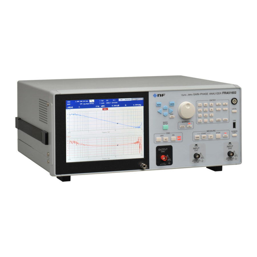
- Page 1 GAIN-PHASE ANALYZER FRA 51602 INSTRUCTION MANUAL (OPERATIONS) NF Corporation...
- Page 3 DA00061635-001 GAIN-PHASE ANALYZER FRA 51602 INSTRUCTION MANUAL (OPERATIONS)
- Page 4 Registered Trademarks National Instruments, LabVIEW, and Measurement Studio are registered trademarks of National Instruments Corporation in the United States. WINDOWS® EMBEDDED 8.1 INDUSTRY PRO Used with permission from Microsoft. Other company names and product names used in this instruction manual may be trademarks or registered trademarks of their respective companies.
- Page 5 ──── Preface ──── Thank you for purchasing the "FRA 51602 GAIN-PHASE ANALYZER". For safe and correct use of this product, please read the "Safety Precautions" section that follows before attempting to use the instrument. ■ Marks and symbols For safe operation by the user and to prevent damage to the instrument, please give attention to the following marks and symbols that are used in this manual.
-
Page 6: Introduction
Preface The manuals provided for the FRA 51602 are listed below. ● Instruction manual (Operations) This manual describes operation of the FRA 51602 from the instrument’s control panel, specifications, maintenance, and other basic matters. ● Instruction manual (Remote Control) This manual describes remote control of the FRA 51602 ... - Page 7 ──── Safety Precautions ──── For safe use of this product, give full attention to the following warnings and cautions. The NF Corporation shall not be held liable for damages that arise from failure to observe these warnings and cautions. This product is a Class I device (with protective conductor terminals) that conforms to the IEC insulation standards.
- Page 8 Safety Precautions Do not modify this product. Never modify this product in any way. Modification might create new risks. The NF Corporation may refuse to service an instrument that has an unauthorized modification. Do not expose this product to water.
- Page 9 Safety Precautions MEASUREMENT CATEGORIES MEASUREMENT CATEGORIES specified by IEC61010-2-030:2017 may be specified for the measurement connectors and other connectors of this instrument based on the location on the mains that is being measured. The relevant MEASUREMENT CATEGORIES are listed below. MEASUREMENT CATEGORY IV (CAT IV): Circuits connected to the source of the building's low-voltage mains installation MEASUREMENT CATEGORY III (CAT III):...
-
Page 10: Table Of Contents
Contents Page 1. Introduction ..........................1-1 1.1 Features ..........................1-2 1.2 Applications ........................1-3 1.3 Operating principles......................1-6 2. Preparation before use ......................2-1 2.1 Checking before use ......................2-2 2.2 Installation ........................... 2-5 2.3 Grounding and power connections .................. 2-11 2.4 Quick operation check ...................... - Page 11 Contents 5.10 Differentiation and integration function ................5-39 5.11 Sequence measurement ....................5-40 5.12 Memory operations ......................5-42 5.13 External reference clock ....................5-52 5.14 Other operations ....................... 5-54 6. File formats ..........................6-1 6.1 Overview ..........................6-2 6.2 Measurement data file format ..................... 6-2 6.3 Measurement conditions file format ...................
- Page 12 Figures and Tables Page Figure 1-1 Example of gain-phase characteristic measurement ..........1-3 Figure 1-2 Example of loop gain measurement ................. 1-4 Figure 1-3 Example of impedance characteristic measurement ..........1-5 Figure 1-4 Principal of frequency transfer characteristic measurement with the FRA 51602 ..1-6 Figure 1-5 Block diagram......................
- Page 13 Figures and Tables Figure 5-4 Frequency change mode and waveform change ........... 5-10 Figure 5-5 Graph display styles ....................5-12 Figure 5-6 Example of phase measurements ................5-16 Figure 5-7 Example of marker search (Bode plot, MAX / MIN / PEAK / BOTTOM) ....5-21 Figure 5-8 Example of marker search (Bode plot, Y1 VALUE) ..........
- Page 14 Figures and Tables Table 2-1 Packing list ........................2-2 Table 3-1 Initial settings 1/8 ...................... 3-84 Table 4-1 Display modes ......................4-22 Table 4-2 Graph axis parameters ..................... 4-23 Table 4-3 Display parameter conversion formulas ..............4-24 Table 6-1 Data file format (header) ..................... 6-3 Table 6-2 Data file format (measurement conditions part) ............
- Page 15 1. Introduction Features ................1-2 Applications ................1-3 Operating principles .............. 1-6 1.3.1 Basic principles ............1-6 1.3.2 Block diagram .............. 1-7 FRA 51602...
-
Page 16: Features
1.1 Features Features The "FRA 51602 GAIN-PHASE ANALYZER" measures the loop gain frequency characteristics of circuits such as inverters and switching power supplies by frequency sweeping. The instrument has a sweep oscillator that uses the synthesizer method for driving the circuit being measured, an analyzer for measuring the response of the circuit being measured to the driving signal and obtaining gain and phase data, and a display screen for presenting the results. -
Page 17: Applications
1.2 Applications Applications This instrument features isolated input and output and highly-accurate measurement over a wide dynamic range, enabling application in a variety of fields such as those listed below. ● Power electronics Loop characteristic measurement of inverters, switching power supplies, etc. -
Page 18: Figure 1-2 Example Of Loop Gain Measurement
1.2 Applications ■ Example of loop gain characteristic measurement The loop gain characteristic is obtained by injecting a perturbance signal into a negative feedback loop and measuring the response to the perturbance signal. The internal signal generator of the instrument is in a floating state with respect to the enclosure, so it is possible to measure the linking characteristic without using an isolation transformer for signal injection. -
Page 19: Figure 1-3 Example Of Impedance Characteristic Measurement
1.2 Applications ■ Example of impedance characteristic measurement The impedance of the DUT can be measured by using this instrument to measure the voltage (v) with CH1 and the current (i) with CH2, and calculating the impedance by taking the vector ratio of CH1 and CH2. The current of the DUT (i) is converted to a voltage with a shunt resistance, current probe, or CT, etc., and the voltage is input to CH2. -
Page 20: Operating Principles
By measuring the EUT input signal (Vin) and output signal (Vout) with the analysis input channels (CH1 and CH2) and calculating the vector ratio (CH1/CH2), the gain and phase at the analysis frequency (f) of the EUT can be obtained. Vout FRA51602 ~ Frequency V2(f) V1(f) |Gain(f)| = |V1(f)| ÷... -
Page 21: Figure 1-5 Block Diagram
1.3 Operating principles 1.3.2 Block diagram In this section, schematic block diagrams of the instrument are presented and the main functions are explained. DC BIAS ~ CONTROL OSC CKT 10 MHz REF IN 10 MHz REF OUT PREAMP CKT PREAMP CKT ~LINE USB- POWER SUPPLY... - Page 22 1.3 Operating principles a) OSC CKT This is the oscillator that generates the measurement signal for the instrument. The synthesizer uses a digital direct synthesis method to have a setting resolution of 10 µHz in the range from 10 µHz to 15 MHz. The synthesizer features both immediate frequency change and phase continuity.
- Page 23 1.3 Operating principles f) REMOTE IF CKT This module performs communication with external controllers for the output of various types of settings and measurement data. It converts between the communication protocols of the GPIB, USB, RS-232, and LAN general interfaces and the internal communication protocol of UI CPU CKT. The USB connector is located on the rear panel and is used for connection to a personal computer that can serve as a controller for this instrument.
- Page 24 1.3 Operating principles (Blank) 1-10 FRA 51602...
-
Page 25: Preparation Before Use
2. Preparation before use Checking before use ............. 2-2 Installation ................2-5 2.2.1 General cautions ................. 2-5 2.2.2 Installation environment ............... 2-5 2.2.3 Rack mounting ................2-6 Grounding and power connections ........2-11 Quick operation check ............2-13 Calibration ................2-14 FRA 51602... -
Page 26: Checking Before Use
2.1 Checking before use 2.1 Checking before use ■ Safety check Before using this product, read the "Safety Precautions" section at the beginning of this manual and perform the safety checks described there. Before connecting the instrument to a power supply, read "2.3 Grounding and power connections" and perform all safety checks fully. - Page 27 2.1 Checking before use PA-001-0419 High withstand voltage clip cable set (3 per set) A high withstand voltage clip cable (1m) that can be used for 600 V CAT II or 300 V CAT III. PA-001-0421 High withstand voltage alligator clip cable set (large) (3 per set) A set of three high withstand voltage alligator clip cables (1m) that can be used for 600 V CAT II or 300 V CAT III.
- Page 28 Thermal printer Model DPU-S445-00B-E Only the printer described above can be used. The NF Corporation does not handle this product. For more information, please refer to the product instruction manual. ! WARNING There are locations of high-voltage inside this product. Do not remove the cover of this instrument.
-
Page 29: Installation
・The instrument has a fan for forced-air cooling. If you notice that the fan is not moving, immediately disconnect the instrument from the power source and contact the NF Corporation or its authorized agent. Continued use of the instrument while the fan is stopped may increase damage to the instrument and make repair difficult. -
Page 30: Rack Mounting
2.2 Installation Signal cables should be placed away from the power cords and other components of this instrument and other equipment that may produce inductive noise. Failure to do so may result in instrument malfunction or measurement error. To ensure accurate measurement, calibrate the instrument after a warm-up period of at least 30 minutes before use. -
Page 31: Figure 2-1 Rack Mounting Kit Assembly Diagram (Jis)
2.2 Installation Figure 2-1 Rack mounting kit assembly diagram (JIS) FRA 51602... -
Page 32: Figure 2-2 Rack Mounting Kit Assembly Diagram (Eia)
2.2 Installation Figure 2-2 Rack mounting kit assembly diagram (EIA) FRA 51602... -
Page 33: Figure 2-3 Rack Mounting Kit Dimensions (Jis)
2.2 Installation Figure 2-3 Rack mounting kit dimensions (JIS) FRA 51602... -
Page 34: Figure 2-4 Rack Mounting Kit Dimensions (Eia)
2.2 Installation Figure 2-4 Rack mounting kit dimensions (EIA) 2-10 FRA 51602... -
Page 35: Grounding And Power Connections
2.3 Grounding and power connections Grounding and power connections ■ The instrument must be grounded. ! WARNING This instrument uses line filters and there is risk of electrical shock if the instrument is not grounded. To prevent electrical shock, connect it to an earth ground so that ground resistance is 100 Ω... - Page 36 2.3 Grounding and power connections ■ In an emergency, the power cord can be used to disconnect the instrument from the mains. ! WARNING Confirm that there is sufficient space around the power inlet of the instrument to ensure that the power cord can be removed easily. Alternatively, plug the power cord into a power outlet that is easily accessible and has sufficient space around it to allow easy removal of the power plug.
-
Page 37: Quick Operation Check
2.4 Quick operation check Quick operation check If the instrument has not been used for a long time after purchase, you should check instrument operation by the procedure described below. Prepare the two calibration cables and the BNC adapter that are supplied with the instrument. -
Page 38: Calibration
If the instrument fails to satisfy the specifications in the performance test, the NF Corporation will make adjustments or calibrate the instrument to restore performance. If calibration or adjustment is necessary, please contact the NF Corporation or its authorized agent. -
Page 39: Panel Operations
3. Panel operations Function and use of each part of the panels ......3-2 3.1.1 Front panel .................. 3-2 3.1.2 Rear panel ................... 3-3 3.1.3 Display screen and keys .............. 3-4 3.1.4 Front panel keys ................3-5 Input and output connectors ..........3-9 Outline of operation screen .......... -
Page 40: Function And Use Of Each Part Of The Panels
3.1 Function and use of each part of the panels 3.1 Function and use of each part of the panels The names and functions of each part of the front panel and rear panel and how each is used are described in the section. -
Page 41: Figure 3-2 Rear Panel
3.1 Function and use of each part of the panels 3.1.2 Rear panel Power inlet The center pin is a grounding terminal. The instrument must be grounded. GPIB connector USB connector Power switch RS-232 connector LAN connector Air exhaust vent VGA connector Nomenclature plate AUX connector... -
Page 42: Display Screen And Keys
3.1 Function and use of each part of the panels 3.1.3 Display screen and keys This instrument is operated by using the keys and LCD touch screen on the front panel. Some operations can be performed either way. All of the input devices are always available for use, so they can be used together to complete single operations. -
Page 43: Front Panel Keys
3.1 Function and use of each part of the panels 3.1.4 Front panel keys ● Menu operation keys and knob • MENU : This displays the top menu on the LCD. The top menu has two pages. Each time the key is pressed moves to the next display in the continuous sequence of Page 1/2 →Page 2/2 →... - Page 44 3.1 Function and use of each part of the panels • ACTIVE : If pressed, the data trace that is indicated by the markers is switched. When the ⊿SET lamp is not lit, each time this button is pressed, the data trace indicated by the main marker is toggled between the measurement data trace and the reference data trace.
- Page 45 3.1 Function and use of each part of the panels ● Measurement controls • DOWN UP : Pressing either of these buttons begins a sweep measurement. DOWN indicates that the sweep direction is from the upper limit of the sweep frequency to the lower limit; UP indicates that the sweep direction is from the lower limit to the upper limit.
- Page 46 3.1 Function and use of each part of the panels ● ENTRY (keypad) This is a set of keys for entering parameter settings. • 0 to 9 . – : These are used to input numerical values • EXP : These are used to input numerical values in exponent format. •...
-
Page 47: Input And Output Connectors
3.2 Input and output connectors 3.2 Input and output connectors ■ Analyzer input connectors (CH1 and CH2) The input and output channels of the instrument analysis module (CH1 and CH2) are each electrically isolated from the instrument enclosure. The oscillator output (OSC) is also isolated. Maximum input voltage : 600 V CAT II or 300 V CAT III (BNC signal to BNC ground) : 1 M Ω... -
Page 48: Figure 3-4 Isolation Withstand Voltage Of The Analysis Module Input Connectors By
3.2 Input and output connectors Using a BNC connector that has exposed metal parts rather than the insulated BNC cable that is provided with this instrument may expose the user to high voltages and the risk of electrical shock. The coaxial BNC cable that is provided with this instrument is designed for safety. -
Page 49: Figure 3-5 Maximum Input Voltage Of The Analysis Module Input Connectors By Frequency
3.2 Input and output connectors ! WARNING Do not apply voltages that exceed the rated isolation voltage. Doing so may result in insulation breakdown and risk of electrical shock. Damage to the instrument may also result. The maximum input voltage is restricted according to the frequency as described below. Applying high voltages at high frequencies may result in a large AC current flowing in floating capacitance within the instrument, creating a risk of damage to the equipment. -
Page 50: Figure 3-6 Isolation Rating Of The Oscillator Output Connector
3.2 Input and output connectors ! WARNING Do not apply voltages that exceed the rated isolation voltage. Doing so may result in insulation breakdown and risk of electrical shock. Damage to the instrument may also result. ■ Oscillator output connector (OSC) The oscillator output (OSC) is electrically isolated from the instrument enclosure. -
Page 51: Figure 3-7 Isolation Withstand Voltage Of The Oscillator Output Connector By Frequency
3.2 Input and output connectors The output impedance is 50 ohms, regardless of whether the output is on or off. Even when the output is set to off, the relay is constantly connected to the internal output amplifier (the relay is always on). For that reason, turning the output on or off does not affect the output impedance. -
Page 52: Figure 3-8 Isolation Withstand Voltage Between Signal Connectors
3.2 Input and output connectors This rating is for when there is no transient overvoltage. For measurements in mains circuits were transient overvoltages can occur, use the MEASUREMENT CATEGORY specifications described previously. ! WARNING Do not apply voltages that exceed the rated isolation voltage. Doing so may result in insulation breakdown and risk of electrical shock. -
Page 53: Figure 3-9 Isolation Withstand Voltage Between The Signal Connectors By Frequency
3.2 Input and output connectors Frequency vs Isolation Voltage (CH1- CH2 - OSC) (AC+DC) AC Vrms 100k DC~ Frequency [Hz] Figure 3-9 Isolation withstand voltage between the signal connectors by frequency This rating is for when there is no transient overvoltage. For measurements in mains circuits where transient overvoltages can occur, use the MEASUREMENT CATEGORY specifications described previously. - Page 54 3.2 Input and output connectors ■ AUX This is a special connector for supplying power to the "5055 SIGNAL INJECTOR / PROBE" (optional) when using the probe for servo loop measurements. Use the cable that is provided with the probe to connect the probe to this instrument.
- Page 55 3.2 Input and output connectors ■ VGA This connector outputs a video signal that is the same as the instrument LCD to an external monitor or projector. Connector : 15-pin mini-D-sub (female), analog RGB component video signal Signal : 800 × 600 pixel (SVGA) Horizontal frequency = 37.9 kHz;...
- Page 56 3.2 Input and output connectors ■ 10 MHz REF IN If a clock signal is input to this connector, that replaces the internal reference clock of the instrument and the instrument will operate on the external clock. The accuracy of the measurement frequency is determined by the accuracy of the clock frequency that is input.
- Page 57 3.2 Input and output connectors ■ 10 MHz REF OUT This connector outputs the clock signal that is actually used as the reference clock by the instrument. When the instrument is operating on an external 10 MHz reference clock (input to 10 MHz REF IN), the frequency that is output is the same as the frequency of the external reference clock.
-
Page 58: Outline Of Operation Screen
3.3 Outline of operation screen 3.3 Outline of operation screen 3.3.1 Menu operation Most of the settings for this instrument are done by touch operation of menus and dialog windows on the LCD screen. The basic menu operation is explained here. A screen with no menus at all is presented immediately after startup, as shown below. - Page 59 3.3 Outline of operation screen ■ Status display This indicates the status of the instrument (remote control, measurement in progress, etc.). Reference clock Measurement Remote control status selection status status • Reference clock selection status : Operating on the internal reference clock : Operating on an external reference clock •...
-
Page 60: Figure 3-11 Top Menu
3.3 Outline of operation screen ■ Top menu Pressing the MENU key when no menus are currently displayed ("Figure 3-10 Screen immediately after startup", etc.) displays the top menu ("Figure 3-11 Top menu"). Top menu Function keys Figure 3-11 Top menu The top menu has two pages. -
Page 61: Figure 3-13 Example Of A Settings Dialog
3.3 Outline of operation screen ■ Settings dialog Tap on the top menu to be set and the settings dialog will be presented. Dialog name Selected menu Settings dialog Item for which there are lower-level settings Figure 3-13 Example of a settings dialog In the settings dialog window, the selected menu item is highlighted. - Page 62 3.3 Outline of operation screen ■ Numerical settings (immediate) You can change parameters by selecting a menu and then pressing the ENTER key. Use the left and right keys to move the cursor to the digit that you want to change. The digit to be changed will be highlighted. Use the up-and-down keys or turn the knob to increase or decrease the value of the selected digit.
- Page 63 3.3 Outline of operation screen ■ Numerical settings (new input) If any of the number keys 0 to 9 of the ENTRY keypad on the front panel are pressed or if the function key [DIRECT NEW] at the bottom of the LCD screen is tapped while the menu is selected, the numerical value input dialog 【...
- Page 64 3.3 Outline of operation screen ■ List operations (immediate setting) In this operation, the settings are made by choosing one from several options, such as waveforms (sinusoidal, square, triangular). With the menu selected, press the ENTER key to open a list box. Use the up and down keys or turn the knob to move the cursor.
- Page 65 3.3 Outline of operation screen ■ Text settings (immediate) The operation is the same as "■ Numerical settings (immediate)" described previously, but alphabetic characters and symbols can be used in addition to numerals. The editing mode is exited and the edited text is set by pressing the ENTER key or the CANCEL key. The characters that can be used with this instrument are shown below.
- Page 66 3.3 Outline of operation screen ■ Text settings (confirming) This operation is the same as "■ Numerical settings (confirming)", but alphabetic characters and symbols can be used in addition to numerals. The values are set by pressing the ENTER key. Pressing the CANCEL key discards the input and restores the text as it was prior to editing.
- Page 67 3.3 Outline of operation screen Tapping on the [SHIFT] button of the【TEXT】dialog changes the character set of the【TEXT】dialog. Uppercase alphabet group Lowercase alphabet group Numerical symbol group 1 Numerical symbol group 2 3-29 FRA 51602...
- Page 68 3.3 Outline of operation screen ■ Text settings (edit) With the menu selected, tap on the [DIRECT EDIT] function key at the bottom of the LCD screen to display the【TEXT】dialog for entering text. The currently set value is displayed and can be edited. The operation is the same as "■...
- Page 69 3.3 Outline of operation screen ■ Execution operations (confirming) To open a confirmation dialog for the selected menu, press the ENTER key. To execute the selected function, tap on the [OK] button of the confirmation dialog. To cancel the operation, tap on the [CANCEL] button.
-
Page 70: Figure 3-15 Graph Display Styles
3.3 Outline of operation screen 3.3.2 Outline of graph display ■ Graph axes The graphs used to display measurement data on this instrument have three axes: X, Y1, and Y2. The graphs also have two display layout styles (SINGLE and SPLIT). The display style can be set using the [Graph] –... -
Page 71: Operation Tree
3.4 Operation tree Operation tree The operation tree for operating this instrument from its panels is presented below. For more information on the keys and screen notation, please refer to "3.1 Function and use of each part of the panels". Front panel MENU key : Top menu display on/off... - Page 72 3.4 Operation tree (Marker operation keys) ACTIVE key : Toggle between the types of measurement data for marking ⊿SET key : Toggle the delta marker set state ⊿SET lamp : Lit when the delta marker set state is on (Keypad) 0 to 9 , and .
- Page 73 3.4 Operation tree 【Measure】: {measurement settings dialog} [INTEGRATION MODE] : Set the integration mode [INTEGRATION] : Set the integration count or time [START DELAY] : Set the start delay [MEAS DELAY] : Set the measurement delay [d/dt] : Set the integration and differentiation calculation 【Sweep】...
- Page 74 3.4 Operation tree [SCALE>] : Graph axis range [MODE] : Select fixed or automatic [X MAX] : Set X axis maximum value [X MIN] : Set X axis minimum value [Y1 MAX] : Set Y1 axis maximum value [Y1 MIN] : Set Y1 axis minimum value [Y2 MAX] : Set Y2 axis maximum value...
- Page 75 3.4 Operation tree Top menu 2/2 【Input】: {input area settings dialog} [MEASURE RANGE] : {set the measurement range} [CH1] : Set CH1 range [CH2] : Set CH2 range [OVER DETECT] : {Set over-level detection} [DETECT LEVEL] : {set the detection level} [CH1] : Set CH1 detection level [CH2]...
- Page 76 3.4 Operation tree [LAN] : Set Ethernet [DHCP] : Select the IP address determination method [IP ADDRESS] : Set IP address [DEFAULT GATEWAY] : Set the default gateway [SUBNET MASK] : Set the subnet mask [DNS] : Set the DNS server [PORT NUMBER] : Display the port number [MAC ADDRESS]...
-
Page 77: Operation Screen Reference
3.5 Operation screen reference Operation screen reference Various settings screens are explained in this section. In the menu explanations that begin on the next page, the methods for performing parameter setting and changing use the format shown below. < Numerical value settings (immediate) > <... -
Page 78: Osc Dialog
3.5 Operation screen reference 3.5.1 OSC dialog ■ [FREQUENCY] : Set the frequency This is the frequency of the signal that is output from the OSC connector. The frequency at which a spot measurement is performed (measurement at a fixed frequency) is set. After a sweep measurement, however, the value is replaced by the last measured frequency. - Page 79 3.5 Operation screen reference ■ [AMPLITUDE] : Set the AC amplitude. This is the amplitude of the signal that is output from the OSC connector. The unit is peak voltage (Vpk). The setting range is 0 to 10 Vpk, but it is limited to ±10 V total, summed with the DC bias setting (DC BIAS).
- Page 80 3.5 Operation screen reference ■ [DC BIAS] – [OUTPUT CONNECTOR] : Set the DC bias output connector This sets the connector from which the DC bias voltage is output. ○ Setting method < List operations (confirming) > • FRONT: The DC bias voltage is output from the OSC connector. •...
- Page 81 3.5 Operation screen reference ■ [STOP MODE] : Set the oscillation stop phase. This selects whether to stop the oscillation instantaneously or to wait until the 0° phase of a sine function before stopping the oscillation. This is useful for the measurement of electrochemical impedance because the amount of charge transfer can be made zero by equalizing the areas of the positive and negative sides of an AC sinusoidal signal.
- Page 82 3.5 Operation screen reference ■ [10MHz REF] – [IN] : Set the reference clock input. This is used to obtain higher frequency accuracy and stability by using an external reference clock that is more accurate than the internal reference clock of the instrument. This is also used to make frequency accuracy common among multiple instruments.
- Page 83 3.5 Operation screen reference ■ [Amplitude Compression] – [FUNCTION] : Set to enabled or disabled. This sets whether or not amplitude compression is performed. ○ Setting method < List operations (confirming) > • OFF : The amplitude compression function is disabled. •...
- Page 84 3.5 Operation screen reference ■ [Amplitude Compression] – [OUTPUT LIMIT] : Set the output limit. This sets the maximum OSC output amplitude. The output amplitude cannot exceed the value set here, even if the target signal amplitude has not been reached. ○...
- Page 85 3.5 Operation screen reference ■ [ Amplitude Compression ] – [CORRECTION FACTOR] : Set the correction factor. This sets the correction factor (control sensitivity) that is used in amplitude adjustment. Usually, 100% works well, but the stability of control may depend on the system being measured. If instability is observed, reduce the correction factor.
-
Page 86: Measure Dialog
3.5 Operation screen reference 3.5.2 Measure dialog ■ [INTEGRATION MODE] : Set the integration mode. This sets the integration mode. For more information on integration operation, refer to section "4.4 Integration". ○ Setting method < List operations (confirming) > • FIX : Set manual integration. - Page 87 3.5 Operation screen reference ■ [START DELAY] : Set the delay for starting measurement. This sets the delay time (or number of cycles) for the beginning of a sweep measurement or a spot measurement. This is set for cases in which a large change in frequency generates a transient response in the circuit under test.
- Page 88 3.5 Operation screen reference ■ [d/dt] : Set the integration and differentiation calculation This function performs calculations on the signals from an acceleration sensor or laser Doppler vibrometer and displays displacement, speed, and acceleration values. For more information, refer to "5.10 Differentiation and integration function".
-
Page 89: Sweep Dialog
3.5 Operation screen reference 3.5.3 Sweep dialog ■ [SEQ SWEEP] : Set sequence measurement. This function performs measurements in the order set in the setting memory of the instrument. It is possible to do measurements at different signal levels for each frequency range. For more information in sequence measurements, refer to "5.11 Sequence measurement". - Page 90 3.5 Operation screen reference ■ [SWEEP RESOLUTION] : Set the sweep resolution. This sets the resolution of the sweep frequency. The number of data points obtained in a sweep measurement is the resolution value set here +1. ○ Setting method <...
- Page 91 3.5 Operation screen reference ■ [SLOW SWEEP] : Set whether the automatic high density sweep is enabled or disabled. This sets whether or not the automatic high density sweep is to be performed. For more information on the automatic high density sweep, refer to "5.8 Automatic high density sweep". ○...
- Page 92 3.5 Operation screen reference ■ [SLOW SWEEP] – [VARIATION] : Set the threshold value for the amount of change. This sets the threshold value for the amount of parameter change that is regarded as a sudden change. The value stored internally for each parameter type that is set by [TYPE]. ○...
-
Page 93: Graph Dialog
3.5 Operation screen reference 3.5.4 Graph dialog ■ [TITLE SET] : Set the graph title. This sets the title of the graph. ○ Setting method < Text settings (confirming) > , < Text settings (new input) > , < Text settings (edit) > Up to 63 characters can be input. - Page 94 3.5 Operation screen reference ■ [GRID] – [STYLE] : Set which gridlines are displayed. This sets the graph axes for which gridlines are displayed. ○ Setting method < List operations (confirming) > • X : Display grid for x-axis only. •...
- Page 95 3.5 Operation screen reference ■ [DISPLAY MODE] – [Y AXIS] : Set the formats of the Y1 and Y2 axes This sets the formats for the Y1 and Y2 axes. ○ Setting method < List operations (confirming) > There are some formats that cannot be selected, depending on the data type of the Y axis. For more information, refer to "4.6 Graph display mode".
- Page 96 3.5 Operation screen reference ■ [ANALYSIS MODE] : Set the analysis mode. This sets the analysis processing method (analysis mode) for the measurement data. ○ Setting method < List operations (confirming) > • CH1/CH2 : Analyze the CH1 measurement data (ratio) with the CH2 measurement data as the reference.
- Page 97 3.5 Operation screen reference ■ [PHASE RANGE] – [SHIFT] : The phase display +360° or −360°. The phase measurement data is displayed with 360° added or subtracted. The setting is effective only when UNWRAP is set for the phase display range; for any other setting, there is no change. ○...
- Page 98 3.5 Operation screen reference ■【Scale】– [X MAX] : X axis maximum value ■【Scale】– [X MIN] : X axis minimum value ■【Scale】– [Y1 MAX] : Y1 axis maximum value ■【Scale】– [Y1 MIN] : Y1 axis minimum value ■【Scale】– [Y2 MAX] : Y2 axis maximum value ■【Scale】–...
-
Page 99: Marker Dialog
3.5 Operation screen reference 3.5.5 Marker dialog ■ [MARKER] : Set the marker display. Set the marker type that is to be displayed. ○ Setting method < List operations (confirming) > • OFF : No marker is displayed. • MAIN : The main marker is displayed. - Page 100 3.5 Operation screen reference ■ [SEARCH VALUE] – [X] : X search value ■ [SEARCH VALUE] – [Y1] : Y1 search value ■ [SEARCH VALUE] – [Y2] : Y2 search value ■ [SEARCH VALUE] – [⊿X] : ⊿X search value ■...
- Page 101 3.5 Operation screen reference ■ [SEARCH X] : X axis search ■ [SEARCH Y1] : Y1 axis search ■ [SEARCH Y2] : Y2 axis search Marker search is performed. The search method is selected by using the function keys. Tapping on a function key begins the search and the marker is moved to the data position that results from the search.
- Page 102 3.5 Operation screen reference • [Y1] : Move the marker to the position of the Y1 value specified by [SEARCH VALUE] – [Y1]. If there are multiple X values, the minimum X value is chosen. • [PREV Y1] : Move the marker to the position of the previous (one smaller) X value. Others are the same as [Y1].
- Page 103 3.5 Operation screen reference X value is chosen. • [PREV ⊿Y2] : Move the marker to the position of the previous (one smaller) X value. Others are the same as [⊿Y2]. • [NEXT ⊿Y2] : Move the marker to the position of the next (one larger) X value. Others are the same as [⊿Y2].
- Page 104 3.5 Operation screen reference ■ [AUTO SEARCH] : Set for automatic search after a sweep is completed. When a sweep measurement is completed, the marker search can be performed automatically according to the settings setting in [AUTO SEARCH]. ○ Setting method <...
-
Page 105: Trace Dialog
3.5 Operation screen reference 3.5.6 Trace dialog ■ [MEAS COPY] : Select the location for storing the measurement data. This copies the measurement data (MEAS DATA). The destination for copying the data is set by tapping a function key. ○ Setting method <... - Page 106 3.5 Operation screen reference ■ [CONDITION VIEW] : Display the settings at the time of data measurement. This displays the set conditions (excerpt) at the time the current active data (MEAS DATA or REF DATA) was measured. The display conditions are not the current settings of this instrument. ○...
-
Page 107: Input Dialog
3.5 Operation screen reference 3.5.7 Input dialog ■ [MEASURE RANGE] – [CH1] : Set the range for CH1. ■ [MEASURE RANGE] – [CH2] : Set the range for CH2. This sets the measurement range. ○ Setting method < List operations (confirming) > •... - Page 108 3.5 Operation screen reference ■ [OVER DETECT] – [ACTION] – [BEEP] : Set the beep to sound for over-level detection. This sets the beep sound to be output when over-level detection occurs. To make the setting, press the ENTER key and make a selection in the listbox by turning the knob or pressing the up and down keys.
- Page 109 3.5 Operation screen reference ■ [WEIGHTING FACTOR] – [CH1] : Set the CH1 weight factor. ■ [WEIGHTING FACTOR] – [CH2] : Set the CH2 weight factor. This value serves as a multiplier for the measurement result. It can be used as a simple correction factor for when a probe, amplifier, or shunt resistance is connected to the circuit being measured.
-
Page 110: Storage Dialog
3.5 Operation screen reference 3.5.8 Storage dialog ■ [CONDITION FILE] : Measurement condition file operations These operations include saving and reading the instrument setting information to and from files. ○ Setting method < Execution operations (immediate) > Press the ENTER key to display a list of measurement condition files (internal memory). 3-72 FRA 51602... - Page 111 3.5 Operation screen reference ■【CONDITION FILE (Internal memory)】 : Measurement conditions file operations (internal memory) These operations include saving and reading the instrument setting information to and from files that are stored in the internal memory of the instrument. ○ Setting method <...
- Page 112 3.5 Operation screen reference ■【CONDITION FILE (USB memory)】 : Measurement conditions file operations (USB memory) These operations include saving and reading the instrument setting information to and from files that are stored in a USB memory device that is installed in the USB port on the front panel of the instrument. ○...
- Page 113 3.5 Operation screen reference ■【DATA FILE (Internal memory)】 : Data file operations (internal memory) These operations include saving and reading measurement data to and from files that are stored in the internal memory of the instrument. ○ Setting method < Execution operations (selection) > ○...
- Page 114 3.5 Operation screen reference ■【DATA FILE (USB memory)】 : Data file operations (USB memory) These operations include saving and reading data to and from files that are stored in the USB memory device that is installed in the USB port on the front panel of the instrument. ○...
- Page 115 3.5 Operation screen reference ■ [HCOPY FILE NUMBER] : Set screen image file number. This sets the serial number of the image file (.bmp) that is to be stored in the USB memory device. Subsequently, this number is incremented each time an image data file is saved. ○...
-
Page 116: Remote Dialog
3.5 Operation screen reference 3.5.9 Remote dialog ■ Common settings ○ Function key functions • [INTERFACE APPLY] : Apply the setting change to the hardware. Even if the remote relationship setting is changed, it will not take effect in the hardware until the [INTERFACE APPLY] function key is pressed. - Page 117 3.5 Operation screen reference ■ [GPIB] – [ADDRESS] : Set the GPIB address. This sets the GPIB address. ○ Setting method < Numerical value settings (immediate setting) > , < Numerical value settings (new input) > , < Numerical value settings (edit) > The setting range is 0 to 30 and the setting resolution is 1.
- Page 118 3.5 Operation screen reference ■ [LAN] – [DHCP] : Select the method for determining the Ethernet IP address. This sets the method for determining the Ethernet IP address. ○ Setting method < List operations (confirming) > • ON : DHCP is enabled •...
-
Page 119: Calibration Dialog
3.5 Operation screen reference 3.5.10 Calibration dialog ■ [CALIBRATION] : Execute calibration. This executes the self-calibration function of the instrument. ○ Setting method < Execution operations (confirm) > Selected menu and press the ENTER key to display the cable connection confirmation message. After confirming the cable connection, press the ENTER key or tap on the [OK] button to start the calibration. -
Page 120: Other Dialogs
3.5 Operation screen reference 3.5.11 Other dialogs ■ [BEEP] : Turns the beep sound on or off. This sets the beep sound (internal buzzer) to on or off. ○ Setting method < List operations (confirming) > • ON : The beep sound is enabled. •... -
Page 121: Basic Setup Dialog
Select the menu and then press the ENTER key to display the [System] dialog. The dialogue only displays information; no settings can be change. The information that is displayed is shown below. • MODEL : Model name "FRA51602" • VERSION : Firmware version •... -
Page 122: Initial Settings
3.6 Initial settings 3.6 Initial settings This instrument is initialized when descrived below. • When shippend from factory All of the settings have the intial values. The content of the setting memory is the same as the intial settings. • When the reset instruction has been given All settings other than setting memory, measurement data, and interface settings are initialized. - Page 123 3.6 Initial settings Table 3-1 Initial settings 2/8 Setting item Parameter range Initial value AMPLITUDE COMPRESSION FUNCTION OFF | ON REF CHANNEL CH1 | CH2 REF LEVEL 1 µ to 600 Vrms 1 Vrms OUTPUT LIMIT 1 m to 10 Vpk 1 Vpk TOLERANCE 1 to 100%...
- Page 124 3.6 Initial settings Table 3-1 Initial settings 3/8 Setting item Parameter range Initial value < Sweep > SEQ SWEEP OFF | 1 to 20 SWEEP LOWER 10 µ to 2 MHz 10 Hz But, < SWEEP UPPER SWEEP UPPER 10 µ to 2 MHz 100 kHz But, >...
- Page 125 3.6 Initial settings Table 3-1 Initial settings 4/8 Setting item Parameter range Initial value < Graph > TITLE SET Up to 63 characters (empty) STYLE SINGLE | SPLIT SINGLE GRID SOLID LINE | BROKEN BROKEN LINE LINE STYLE OFF | X | X-Y1 | X-Y2 | X-Y1 X-Y1-Y2 DISPLAY MODE...
- Page 126 3.6 Initial settings Table 3-1 Initial settings 5/8 Setting item Parameter range Initial value < Marker > MARKER OFF | MAIN | MAIN&⊿ MAIN −1.0 T to +1.0 T SEARCH VALUE −1.0 T to +1.0 T −1.0 T to +1.0 T −1.0 T to +1.0 T ⊿X −1.0 T to +1.0 T...
- Page 127 3.6 Initial settings Table 3-1 Initial settings 6/8 Setting item Parameter range Initial value < Storage > – – CONDITION FILE (1 to 20) – – DATA FILE (1 to 20) HCOPY FILE NUMBER 000 to 999 *1: Only typical settings are saved. 3-89 FRA 51602...
- Page 128 3.6 Initial settings Table 3-1 Initial settings 7/8 Setting item Parameter range Initial value < Remote > SELECT USB | GPIB | RS-232 | LAN GPIB ADDRESS 0 to 30 RS-232 BAUD RATE 4800 | 9600 | 19200 | 9600 38400 |57600 | 115200 | 230400 FLOW CONTROL...
- Page 129 3.6 Initial settings Table 3-1 Initial settings 8/8 Setting item Parameter range Initial value < Calibration > EQUALIZE ON | OFF < Other > BEEP ON | OFF DATE/TIME YEAR 1998 to 2099 (when shipped) MONTH 1 to 12 (when shipped) DATE 1 to 31 (when shipped)
- Page 130 3.6 Initial settings (Blank) 3-92 FRA 51602...
-
Page 131: Basic Operation
4. Basic operation 4.1 Display and operation for powering up ........4-2 4.1.1 What to check before turning the power on ......... 4-2 4.1.2 Turning power on and off ............. 4-2 4.1.3 Restoration of settings at power on ..........4-3 4.1.4 Startup screen and operation ............ -
Page 132: Display And Operation For Powering Up
4.1 Display and operation for powering up 4.1 Display and operation for powering up 4.1.1 What to check before turning the power on Before turning the instrument power switch on, read "2.3 Grounding and power connection" and check the instrument grounding and power supply voltage. 4.1.2 Turning power on and off The instrument has the three operating modes listed below. -
Page 133: Restoration Of Settings At Power On
4.1 Display and operation for powering up 4.1.3 Restoration of settings at power on The settings of the instrument at startup depends on how the power was turned off when the instrument was last used. In any case, however, the oscillator output is always off immediately after startup. Operating state (setting A) ・Power switch at "... -
Page 134: Startup Screen And Operation
In that case, set the power switch on the rear panel to the off position, wait at least five seconds, and then set the power switch back to the on position. If the error occurs again, the instrument may be malfunctioning, so please contact the NF Corporation or its authorized agent. Start up screen When the instrument starts up normally, the initial screen is displayed. -
Page 135: Simple Operation For The First Use
4.2 Simple operation for the first use Simple operation for the first use The procedures for performing a basic measurement is described here. 4.2.1 Common operations ■ Initialization Initialize this instrument as follows. Select【Other】-[RESET] and press the ENTER key to display the confirmation message on the LCD screen. -
Page 136: Figure 4-1 Connections For Loop Gain Measurement
β ~ Figure 4-1 Connections for loop gain measurement The set up and measurement method for a typical DC-DC converter are explained below. OUTPUT RECT FRA51602 ~ ERROR Injection resistance VREF Several 10Ω (<<R1) Figure 4-2 Example of connections for measuring the loop gain of a DC-DC converter The injection resistance in the above diagram is inserted to prevent an open loop if the measurement probe is removed from the circuit being measured. - Page 137 4.2 Simple operation for the first use ! Warning A large output may be generated if the control loop is broken, resulting in possible damage to the equipment under test or risk of injury to the user. Ensure that an open control loop does not occur even if the probe is disconnected from the instrument by using an injection resistance.
- Page 138 4.2 Simple operation for the first use 6) In the same way, turn the knob to find the frequency at which the phase is closest to 0°. The gain at that frequency is the gain margin. Because the frequency is relatively high, it may be difficult to clearly read the gain margin because of noise, etc.
-
Page 139: Figure 4-3 Nyquist Plots Obtained From Actual Measurements
0→∞ Aβ vector locus −Aβ vector locus (FRA51602 measurement data) Figure 4-3 Nyquist plots obtained from actual measurements Although the position for indicating the stability limit is shifted, the vector locus is also rotated 180° at the origin, so the method for determining stability is the same as for an ordinary Nyquist plot. -
Page 140: Figure 4-4 Example Of Connections For Gain-Phase Measurement
Figure 4-4. When measuring the input-output characteristics (Figure 4-4 (a)), it is convenient to use the BNC adapter that is provided with the instrument. Measurement accuracy can be increased by placing the BNC adapter on the input side of the equipment under test. FRA51602 BNC adapter (accessory) Figure 4-5 Example of connections for transfer characteristic measurement Follow the procedure described below for instrument set-up and performing measurements. -
Page 141: Figure 4-6 Example Of Connections For Measuring Impedance
4.2 Simple operation for the first use 4) Press the MEASURE DOWN key on the front panel to perform a sweep measurement and wait until the measurement is completed. 5) Turning the knob moves the marker on the measurement data. You can read the gain or phase at any frequency. - Page 142 4.2 Simple operation for the first use Follow the procedure described below for instrument set-up and performing measurements. 1) Initialize settings. 2) Set the item that is to be displayed on the graph Y axis. Set【Graph】dialog-[DISPLAY MODE][Y AXIS] to LOG R-LIN θ. For more information, read "3.5.4 Graph dialog".
-
Page 143: Figure 4-7 Example Of Connections For Measuring Impedance With High-Power
4.2 Simple operation for the first use If the OSC output of the instrument is amplified with a power amplifier, it is possible to measure the impedance by applying a large voltage/current to the DUT. A large amplitude or DC bias (voltage/current) can be used to measure a change in the impedance characteristic caused by a nonlinearity such as saturation of a magnetic or dielectric material. -
Page 144: Oscillator Settings
4.3 Oscillator settings Oscillator settings The basic setup and operation of the oscillator are described in this section. ■ Setting the output on or off Use the OSC key on the front panel. Output lamp The output lamps that are to the right of the AC/DC ON key are lit when corresponding AC or DC is being output. - Page 145 4.3 Oscillator settings The frequency is set by tapping the function keys at the bottom of the LCD screen. [SWEEP MIN -> FREQ] : Set the lower limit for the sweep frequency. [SWEEP MAX -> FREQ] : Set the upper limit for the sweep frequency. [MKR ->...
- Page 146 4.3 Oscillator settings ■ Setting the DC bias The DC bias that is applied to the circuit or DUT is set in the range from −10 V to +10 V. Select【OSC】-[DC BIAS]. The DC bias is set by tapping the function keys at the bottom of the LCD screen. [DIRECT NEW]: Set an arbitrary DC bias value.
- Page 147 4.3 Oscillator settings ■ Setting the waveform Select the oscillator output waveform from among sinusoidal (SINE), square (SQUARE), and triangular (TRIANGLE). Select【OSC】-[WAVEFORM]. The waveform that is set is displayed as an icon in the upper part of the screen. Normally, the sinusoidal waveform (SINE) is used. The measurement accuracy of this instrument is always specified for the sinusoidal waveform.
-
Page 148: Integration
4.4 Integration Integration This instrument performs measurement processing as a discrete Fourier transform (DFT) in units of one cycle of the measurement waveform. By nature, the DFT essentially removes noise and high-frequency harmonics. However, if the signal component being measured is small relative to the noise, or if highly accurate measurement is required, the accuracy of measurement can be improved by increasing the integration period (the number of integrations). - Page 149 4.4 Integration must be performed at least three times to obtain the statistic.) Furthermore, it is not possible to predict the time required to finish the sweep in advance. Before using automatic integration, you should perform preliminary experiments. ■ Integration settings This sets the number of integration rounds or duration for the manual integration mode (FIX), and the upper limit in automatic integrarion mode.
-
Page 150: Measurement Control
4.5 Measurement control Measurement control This section explains how to start and stop the measurement process of this instrument. The instrument can perform sweep measurements and spot measurements. Sweep measurement : The frequency response characteristic is measured by sweeping over frequencies and the measurement results are displayed as a graph. - Page 151 4.5 Measurement control ■ Repeated measurements Pressing the REPEAT key sets the instrument to automatically repeat measurements. If the REPEAT lamp is lit, measurements are repeated for both sweep measurements and spot measurements. If the REPEAT lamp is not lit, the instrument goes into standby mode after a measurement is completed. Pressing the REPEAT toggles the REPEAT lamp that is above the key on and off.
-
Page 152: Graph Display Mode
4.6 Graph display mode Graph display mode The basic graph display mode settings are explained in this section. For more information on the functions, refer to "5.5 Graph display". ■ Setting the display mode Use【Graph】-[DISPLAY MODE] to select what is to be displayed on the X axis, Y1 axis, and Y2 axis of the graph. - Page 153 4.6 Graph display mode The axis setting parameters are described and their units are given in the following table. Table 4-2 Graph axis parameters Analysis mode Axis setting Description Unit CH1/CH2 SWEEP Frequency CH2/CH1 | Gain | None (ratio) | Gain | θ...
- Page 154 4.6 Graph display mode ■ Converting measurement data to display parameters The formulas for converting the various parameter formats that are used for measurement and display by this instrument are explained in this section. . . Let V and V respectively denote the voltage vectors obtained by Fourier transforms of the signals measured at analysis input connectors CH1 and CH2.
-
Page 155: High-Frequency Measurements
4.7 High-frequency measurements High-frequency measurements At frequencies above several hundreds of kilohertz, the effect of signal cables on measurement error tends to increase with the frequency. The main points of caution for measuring at high frequencies are explained in this section. a) Auto-range In the default settings, CH1 and CH2 are both set to auto-range. - Page 156 4.7 High-frequency measurements c) Cable length and routing The output BNC connector of OSC and the input BNC connectors of CH1 and CH2 are each electrically isolated from the instrument enclosure. The impedance is high and can be treated as approximately infinite impedance for DC or at mains frequencies.
-
Page 157: Advanced Operation
5. Advanced operation Analysis mode ............... 5-2 Delay ..................5-3 Input settings ................. 5-5 Oscillator control ..............5-8 Graph display ..............5-12 Marker operations ............... 5-20 Amplitude compression............5-26 Automatic high density sweep ..........5-29 Error correction ..............5-31 5.10 Differentiation and integration function ....... 5-39 5.11 Sequence measurement ............. -
Page 158: Analysis Mode
5.1 Analysis mode 5.1 Analysis mode There are four possible analysis settings for data measured on two channels: (CH1/CH2), (CH2/CH1), (CH1), and (CH2). The mode is set using【Graph】– [ANALYSIS MODE]. Normally, the mode that is set when the instrument leaves the factory (CH1/CH2) is used. The analysis mode settings (CH1/CH2) and (CH2/CH1) differ in which channel used for the reference signal, so the display of the gain and phase is reversed. -
Page 159: Delay
5.2 Delay 5.2 Delay If there is a response delay element in the equipment under test and the measurement frequency is changed, the transient response causes an error in the measurement data. When using this instrument to measure frequency response, that error can be reduced by inserting a delay after the frequency change and before the measurement is started. - Page 160 5.2 Delay ■ When the delay is set in units of cycles The measurement delay and measurement start delay are both converted to a number of cycles (time of one cycle of the measurement frequency × the set number of cycles). Therefore, during sweep measurement, measurement is performed with different delay time depending on the measurement frequency.
-
Page 161: Input Settings
5.3 Input settings Input settings 5.3.1 Measurement range The measurement ranges for CH1 and CH2 can be set independently. The setting range is shown below. Fixed range : 1–3 sequences in the range from 30 mV to 300 V, and 600 V Auto-range : AUTO The setting is done using【Input】–... - Page 162 5.3 Input settings 5.3.2 Over-level detection This function monitors the input signal level for CH1 and CH2 and performs operations such as sounding the buzzer when the signal exceeds the set level. Over-level detection level Operation when over-level is detected ■...
- Page 163 5.3 Input settings ■ Over-level detection and measurement data When an over-level detection occurs, the measurement data becomes NaN (Not a Number). The frequency data for which over-level was detected is not plotted on the graph. If an over-level is detected and measurement is stopped (【Input】– [OVER DETECT] – [ACTION] – [SWEEP STOP] is on), the data from the beginning of the sweep up to the time of the over-level detection is retained.
-
Page 164: Oscillator Control
5.4 Oscillator control Oscillator control For information on the basic settings (frequency, AC amplitude, and DC bias) and on/off control, refer to "4.3 Oscillator settings". This section explains more advanced oscillator control. 5.4.1 On/off mode You can select between two modes for turning the oscillator output on and off. In the QUICK mode, the output is turned on or off immediately;... -
Page 165: Figure 5-3 Oscillation Stop Mode Setting And Change In Output Voltage
5.4 Oscillator control 5.4.2 Oscillator stop mode You can specify the stop (OFF) timing of oscillator output by selecting from [QUICK] and [0° SYNC]. The setting is done using【OSC】– [STOP MODE]. [QUICK] : The output is turned off immediately, regardless of the signal phase. [0°... -
Page 166: Figure 5-4 Frequency Change Mode And Waveform Change
5.4 Oscillator control 5.4.3 Frequency change mode The timing for changing the frequency during a sweep measurement and the timing for changing the frequency when the frequency setting is changed can be selected as [0° SYNC] or [ASYNC]. The setting is done with【Sweep】–... - Page 167 5.4 Oscillator control 5.4.4 Measurement synchronization This function automatically turns the oscillator output off when the measurement is completed. The setting is done with 【 OSC】 – [ON/OFF SYNC]. This function is used when it is not desirable for the measurement signal to be applied to the equipment under test for a long period of time.
-
Page 168: Graph Display
5.5 Graph display 5.5 Graph display 5.5.1 Setting the title Set the title text for the data that is being displayed. The text that is set is displayed at the top of the graph. When the data is saved to internal or externalmemory, the title is also included. The title text is set with【Graph】–... - Page 169 5.5 Graph display ■ SPLIT display restrictions When a Nyquist plot is displayed with the SPLIT graph display style, a small graph is displayed in the upper half of the screen and the lower half is empty. For all diagrams other than Bode plots, use the SINGLE display style.
- Page 170 5.5 Graph display 5.5.4 Trace operation The graphing function of this instrument can display two types of traces, MEAS TRACE and REF TRACE. Each trace can have Y1 data and Y2 data, which can each be set individually to be displayed or not displayed.
- Page 171 5.5 Graph display ■ Deleting a trace The data for the respective traces can be deleted with 【 Trace】 – [DELETE MEAS] and – [DELETE REF]. Deleted data cannot be recovered, so perform this operation with care. 1) Tap OK. ■...
-
Page 172: Figure 5-6 Example Of Phase Measurements
5.5 Graph display 5.5.5 Phase display This function sets the display range for phase. The setting is done with【Graph】– [PHASE RANGE]. : Phase is displayed within the range of −180° ≦ θ < +180°. [±180°] [0° to +360°] : Phase is displayed within the range of 0° ≦θ < +360°. [−360°... - Page 173 5.5 Graph display ■ The unwrapped phase display function For the [UNWRAP] display setting, a wrapped phase display is performed, with the phase measurement value at the sweep starting frequency (the lower-limit frequency for an upsweep or the upper-limit frequency for a downsweep) as the reference value. Thus, when DUTs that have entirely the same phase characteristics are measured by upsweep or downsweep measurement, the results are displayed in graphs that differ in phase by an integer multiple of 360°.
- Page 174 5.5 Graph display ■ The aperture setting 【Graph】– [PHASE RANGE] – [APERTURE] is the value for the width of the moving average window of the phase characteristic for the group delay display. 3) Enter the moving average window width. 1) Select APERTURE. 2) Tap Larger values for the setting reduce noise and produce a smooth group delay characteristic, but abrupt changes are not represented.
- Page 175 5.5 Graph display 5.5.6 Setting the scale This setting determines the range of the graph X, Y1, and Y2 axes. Usually, the AUTO setting is convenient, because the ranges are adjusted automatically to suit the data that is being displayed. The FIX setting allows the display range to be set to an arbitrary value.
-
Page 176: Marker Operations
5.6 Marker operations 5.6 Marker operations You can display a marker on the graph and read the corresponding measurement value. The marker value is displayed as the number in the marker display area at the top of the graph. Markers can be moved by using the knob on the front panel and the data that is specified by the marker can be selected by using the two keys (ACTIVE and ⊿SET) that are located below the knob. -
Page 177: Figure 5-7 Example Of Marker Search (Bode Plot, Max / Min / Peak / Bottom)
5.6 Marker operations ■ Marker search function In addition to using the knob to manually move the marker and read data values, it is possible to perform an automatic search for locations that match specified conditions. The search conditions include maximum value (MAX), minimum value (MIN), specified value(VALUE), maximal value (PEAK), and minimal value (BOTTOM). -
Page 178: Figure 5-8 Example Of Marker Search (Bode Plot, Y1 Value)
5.6 Marker operations The marker search locations after the value search has been performed are illustrated in Figure 5-8. This example is for the Y1 value search, but it also applies to Y2 values. Y1 VALUE X (Frequency) (1) (2) (3) (4) (5) NEXT Y1 Figure 5-8 Example of marker search (Bode plot, Y1 VALUE) The locations from ⊿Y1 and ⊿Y2 marker search are illustrated in Figure 5-9. -
Page 179: Figure 5-11 Example Of Marker Search (Nyquist Plot, ⊿X)
5.6 Marker operations Y (Imag) MAIN MARKER NEXT ⊿X * ⊿X ⊿ X (Real) ⊿X VALUE Figure 5-11 Example of marker search (Nyquist plot, ⊿X) A PREV search moves the marker in the reverse order of a NEXT search. ■ Marker search procedure (1) When performing a value search, set the value in the parameters of【Marker】–... - Page 180 5.6 Marker operations ■ Automatic marker search when a sweep is completed It is possible to register the marker search settings in advance so that the marker search can be performed automatically when a sweep measurement is completed. Select the search item with【Marker】– [AUTO SEARCH].
- Page 181 5.6 Marker operations (Example 2) : Automatic search for the phase margin of a negative feedback loop In a feedback loop, the frequency for which the pass gain is 0 dB is the loop bandwidth. The phase at that frequency is the phase margin. •...
-
Page 182: Amplitude Compression
As illustrated in Figure 5-12, this instrument can automatically adjust the oscillator amplitude so that the amplitude of the output of the equipment under test (EUT) A1 remains constant for the measurement, regardless of the frequency characteristics of A1. FRA51602 gain The amplitude here should be constant. -
Page 183: Figure 5-14 Operation For Amplitude
5.7 Amplitude compression The internal operation of this instrument for amplitude compression is described below. 1) Measurement is performed once with the oscillator output voltage at the value that is currently set. 2) The amplitude measured at the reference channel [REF CHANNEL] is compared with the target amplitude [REF LEVEL]. - Page 184 5.7 Amplitude compression that the measured value of the reference channel has this value. [OUTPUT LIMIT] : This is the maximum amplitude of the oscillator (output control). [TOLERANCE] : This is the permissible error of the target level. [RETRY TIMES] : The maximum number of times the process is repeated.
-
Page 185: Automatic High Density Sweep
5.8 Automatic high density sweep Automatic high density sweep This function automatically increases the density of sweep measurement only in the vicinity of large changes in measurement data. By increasing the measurement resolution only where necessary, accurate results can be obtained in a short time. This function compares the measurement value difference between adjacent measurement points |d .) with the threshold value [VARIATION]. - Page 186 5.8 Automatic high density sweep [VARIATION] : This is the parameter change threshold. If the amount of change relative to the measurement at the previous frequency exceeds the value set here, it is judged to be a sudden change and the automatic high density sweep is performed. The parameter setting ranges and other such information is described in "3.5.3 Sweep dialog".
-
Page 187: Error Correction
5.9 Error correction Error correction The error correction function of this instrument is explained here. Input Corrected Calibration Equalizing weighting data Figure 5-16 Error correction data flow The targets for error correction are listed below. • Calibration : The error of the instrument itself is corrected. •... -
Page 188: Figure 5-17 Connections For Calibration
5.9 Error correction 5.9.1 Calibration Connect the oscillator output of the instrument to the signal input to perform the self error correction (calibration). Use the calibration cables and BNC adapter that are provided with the instrument. BNC adapter Cables for calibration (provided) (provided) Figure 5-17 Connections for calibration... - Page 189 On error detection The calibration error may indicate a problem with the instrument. Try turning the power on again and performing the calibration once more. If the error occurs again, please contact the NF Corporation or its authorized agent. ■ Cautions concerning calibration The error factors listed below are related to the measurement itself.
- Page 190 5.9 Error correction 5.9.2 Input weighting This function performs gain correction on the results of measurements performed with a 10:1 passive probe intended for use with oscilloscopes or pre-amplifiers, etc. connected to the input connectors of the instrument (CH1 and CH2) and displays the results. The correction is converted to an input signal level for the measurements.
- Page 191 5.9 Error correction ■ Constraints on the input weighting function The values that can be set with the input weighting function are limited to real numbers (not complex numbers) that are independent of the measurement frequency. For that reason, the phase does not change when the amplitude and gain of the measurement results are corrected.
-
Page 192: Figure 5-18 Example Of Connections For Gain-Phase Measurement
5.9 Error correction 5.9.3 Equalizing This function corrects for errors of externally connected cables and probes, etc. The method of correcting for systematic error is explained with the connection example shown in Figure 5-18. FRA51602 Probe1 Probe2 BNC adapter (provided) Figure 5-18 Example of connections for gain-phase measurement The set up and measurement procedure is described below. - Page 193 5.9 Error correction 5) When the sweep measurement is completed, select【Trace】– [MEAS COPY] and tap the [EQUALIZE CORR MEM] function key to copy the measurement data to the internal equalizing memory of the instrument. 6) Set【Calibration】– [EQUALIZING] to [ON]. 7) Restore the original connections as they were prior to removing the EUT in step 3 ("Figure 5-18 Example of connections for gain-phase measurement").
- Page 194 5.9 Error correction ■ Cautions concerning equalizing • Even if the correction data has been measured and copied to the equalizing memory, the function will not work unless it has been enabled by setting【Calibration】– [EQUALIZING] to [ON]. • When equalizing is performed, the amplitude of CH2 is normalized to 1.0 (Vrms) and displayed. Corrected results are obtained for gain and phase, but please note that the amplitudes displayed for CH1 and CH2 differ from the measured amplitudes.
-
Page 195: Differentiation And Integration Function
5.10 Differentiation and integration function 5.10 Differentiation and integration function This function performs differentiation, second-order differentiation, integration, and double integration of the measurement data in the time domain. This is used when doing displacement–speed–acceleration conversion in the measurement of transfer characteristics (gain-phase measurement). Second-order differentiation Differentiation Differentiation... -
Page 196: Sequence Measurement
5.11 Sequence measurement 5.11 Sequence measurement Sequence measurement is a function for reading setting memories in numerical order and performing sweep measurements. For one sweep, the frequency range can be divided into up to 20 parts and measurement can be performed with different amplitudes, integration settings, etc. for each frequency range. - Page 197 5.11 Sequence measurement ■ Cautions concerning sequence measurement • The validity check is not performed for the sweep frequency range of each setting memory number. Depending on the settings in the memory, the sweep frequencies may be greatly separated or the sweep ranges may overlap when the memory number is changed.
-
Page 198: Memory Operations
5.12 Memory operations 5.12 Memory operations Measurement conditions and measurement data can be saved to internal memory or to a USB memory device and can be read from memory and reused. It is also possible to save an image of the LCD screen to USB memory as a file in bitmap format (.bmp). - Page 199 5.12 Memory operations ■ Restoring measurement conditions (internal memory) 1) Select the memory 3) Tap OK 2) Tap [LOAD] Use the control knob or the cursor keys to select the memory from which to restore the measurement conditions and then tap the [LOAD] function key. The load confirmation dialog will be displayed. Tap on the OK button to restore the selected measurement conditions.
- Page 200 5.12 Memory operations ■ Saving measurement conditions (USB memory device) Insert a USB memory device into the USB port on the front panel. 1) Tap [⇒USB MEM] 2) Tap [SAVE] 3) Enter the file name 5) Tap OK 4) Tap ENTER Tap on the [⇒USB MEM] function key to display a list of the files in the USB memory device.
- Page 201 5.12 Memory operations ■ Restoring measurement conditions (USB memory device) Insert a USB memory device into the USB port on the front panel. 2) Select the measurement conditions file to restore. 1) Tap [⇒USB MEM] 3) Tap [LOAD] 4) Tap OK Use the control knob or the cursor keys to select the file from which to restore the measurement conditions and then tap the [LOAD] function key.
- Page 202 5.12 Memory operations 5.12.2 Measurement data Measurement data can be saved to the internal memory of the instrument or to a USB memory device and then loaded at a later time for use. The data that can be stored is MEAS TRACE and REF TRACE data. The saved measurement data can be loaded for display in graph form or for use as error correction data by the equalizing function, etc.
- Page 203 5.12 Memory operations ■ Loading measurement data (internal memory) 1) Select memory to read 2) Tap [LOAD] 3) Select the destination 4) Tap OK Use the control knob or the cursor keys to select the memory from which to read the measurement data and then tap the [LOAD] function key.
- Page 204 5.12 Memory operations ■ Saving measurement data (USB memory device) Insert a USB memory device into the USB port on the front panel. 1) Tap [⇒USB MEM] 2) Tap [SAVE] 4) Enter the file name 5) Tap ENTER 3) Select the data to save 6) Tap OK Tap on the [⇒USB MEM] function key to display a list of the files in the USB memory device.
- Page 205 5.12 Memory operations ■ Loading measurement data (USB memory device) Insert a USB memory device into the USB port on the front panel. 2) Select file to load 1) Tap [⇒USB MEM] 3) Tap [LOAD] 5) Tap OK 4) Select the load destination Tap on the [⇒USB MEM] function key to display a list of the files in the USB memory device.
- Page 206 5.12 Memory operations ■ Other operations (USB memory) • [DELETE] function key This deletes the selected file. • [RENAME] function key This changes the name of the selected file. • [CREATE NEW FOLDER] function key This creates a new folder. •...
- Page 207 5.12 Memory operations 5.12.3 LCD screen capture This function can capture an image of the LCD screen and save it to USB memory. Insert a USB memory device into the USB port of the front panel and press the SCREEN COPY key to create a bitmap file in the USB memory device.
-
Page 208: External Reference Clock
5.13 External reference clock 5.13 External reference clock This instrument uses an internal crystal oscillator as the reference clock, but an external 10 MHz clock signal can also be used. Generally, an external reference clock is used for the following purposes. •... - Page 209 5.13 External reference clock Even if a valid 10 MHz reference clock signal is being input to the 10 MHz REF IN connector, the instrument will still operate on the internal reference clock if【OSC】– [10 MHz REF] – [IN] is set to [DISABLE].
-
Page 210: Other Operations
5.14 Other operations 5.14 Other operations 5.14.1 Beep settings If【Other】– [BEEP] is set to [ON], a click sound is output for button operations and a pop-up sound is output when a message is displayed. 5.14.2 Internal clock settings ■ Setting the date and time The date and time of the internal clock can be set with 【... - Page 211 5.14 Other operations 5.14.3 Touch panel adjustment Touch panel adjustment is done when there is a difference between the location on the screen that is touched and the position that is recognized by the instrument. It is not normally necessary to perform the adjustment.
- Page 212 5.14 Other operations 5.14.4 Adjusting the LCD backlight brightness The backlight brightness adjustment can be done with【Other】– [BRIGHTNESS]. The brightness value can be set in the range from 0 to 100, with larger values indicating greater brightness. If the value is set to 0, however, the backlight is not completely turned off.
- Page 213 5.14 Other operations 5.14.6 Restoring factory settings This function restores all of the instrument setting to the values that were set when the instrument left the factory. 1) Tap [INITIALIZE] 2) Tap [OK] Performing the operation described above returns all settings, including the remote interface settings, the measurement data saved in internal memory, and the measurement condition files saved in internal memory (which are used in sequence measurement), to the values that were set when the product was shipped from the factory.
- Page 214 5.14 Other operations 5.14.7 Printer A hard copy of the LCD screen of the instrument can be printed easily by using the thermal printer described below. (That product is not carried by the NF Corporation.) Manufacturer : Seiko Instruments Inc. Product...
-
Page 215: File Formats
6. File formats 6.1 Overview ................. 6-2 6.2 Measurement data file format ..........6-2 6.3 Measurement conditions file format ........6-6 6.4 Screen capture file format ............ 6-10 FRA 51602... -
Page 216: Overview
6.1 Overview 6.1 Overview This instrument can save measurement data, measurement conditions, and screen capture data to files located on a USB memory device that is connected to the USB port on the front panel of the instrument. The data in the measurement data files and measurement conditions files can be read and used by your instrument or other FRA 51602 instruments. -
Page 217: Figure 6-2 Structure Of The Measurement Data File (With Sequence Measurement)
The measurement conditions part and the measurement data part have the same format, regardless of whether there is sequence measurement or not. Table 6-1 Data file format (header) Line Format (example) Description number IDN, NF Corporation, FRA51602, Manufacturer, model, 0123456, Ver1.00 serial number, firmware version FileFormatVer, 1.00 File format version FileType, DATA... - Page 218 6.2 Measurement data file format Table 6-2 Data file format (measurement conditions part) Relaive line number Format (example) Description DataType, RAW The type of data in the file is fixed as "RAW" DataNum, (NR1) The number of data items (the sweep resolution + 1) Sequence, (NR1) The sequence number.
- Page 219 6.2 Measurement data file format The line number of the first line of the measurement conditions part relative to the beginning of the file can be calculated with the formula shown below, denoting the number of data items (DataNum) for sequence number m as n ) + …...
-
Page 220: Measurement Conditions File Format
End of file Figure 6-3 Structure of the measurement conditions file Table 6-4 Measurement conditions file format (header) Line number Format (example) Description IDN, NF Corporation, FRA51602, Manufacturer, model, 0123456, Ver1.00 serial number, firmware version FileFormatVer, 1.00 File format version FileType, CON... - Page 221 6.3 Measurement conditions file format AmplitudeCompressionRefCh, {1|2} Sets the amplitude compression function reference channel AmplitudeCompressionRefLevel, Sets the amplitude compression function (NR3) target level (Vrms) AmplitudeCompressionOutputLimit, Sets the amplitude compression function (NR3) output limit (Vrms) AmplitudeCompressionTolerance, Sets the amplitude compression function (NR1) permissible error (%) AmplitudeCompressionRetry, (NR1)
- Page 222 6.3 Measurement conditions file format {ASYNC|0PHASE} Immediate change (ASYNC), Change at 0° phase (0PHASE) SlowSweep, {ON|OFF} Sets the slow sweep function to enabled (ON) or disabled (OFF). SlowSweepChannel, {1|2} Automatic high density sweep reference channel SlowSweepVarType, {dBR|R|P|a|b} Automatic high density sweep monitored parameter SlowSweepVarDBR, (NR2) Automatic high density sweep...
- Page 223 6.3 Measurement conditions file format GraphScaleY1, (NR3), (NR3) Graph Y1 axis range lower limit to upper limit GraphScaleY2, (NR3), (NR3) Graph Y2 axis range lower limit to upper limit MarkerMode, Select the marker display mode {OFF|MAIN|MAIN&DELTA} MarkerSearchValueX, (NR3) Marker X search value ⊿X search value Marker MarkerSearchValueDeltaX, (NR3)
-
Page 224: Screen Capture File Format
6.4 Screen capture file format (not used) (not used) (not used) (not used) (not used) (not used) (not used) (not used) OthersDateTime, (CRD), (CRD) The date and time the file was saved in the format yyyy.mm.dd, hh:mm:ss 6.4 Screen capture file format The LCD screen capture data is saved to a file in uncompressed BMP (Microsoft Windows Bitmap Image) format with a pixel resolution of 800 ×... -
Page 225: Troubleshooting
7. Troubleshooting 7.1 Error messages ..............7-2 7.1.1 Errors that occur when the instrument power is turned on ..7-2 7.1.2 Errors that occur during panel operation ........7-3 7.1.3 Errors that occur during measurement ........7-4 7.1.4 Other errors ................7-5 7.2 Information messages ............ -
Page 226: Error Messages
If the instrument requires repair, please contact the NF Corporation or its authorized agent. When requesting repair, please include the error code (error number) and a description of the error message that was displayed. -
Page 227: Errors That Occur During Panel Operation
7.1 Error messages 7.1.2 Errors that occur during panel operation The errors that may occur during panel operation are listed in Table 7-2. Table 7-2 Panel operation errors Error message Description and cause Handling -2048 Data out of range. The set parameter value lies outside Set a value that is within the the specified range. -
Page 228: Errors That Occur During Measurement
7.1 Error messages Table 7-2 Panel operation errors (continued) Error message Description and cause Handling -6145 There is already a file of A file of the same name already exists, Specify a different file the same name. so the specified name cannot be used to name. -
Page 229: Other Errors
-7171 Remote section no There is no response from the remote malfunctioning. In that response. interface section in internal case, contact the NF communication. Corporation or its -7172 Internal error. There was an internal processing error. authorized agent. -
Page 230: Information Messages
7.2 Information messages Information messages Measurements that may be displayed when operations or measurements are completed normally are explained in this section. An example information message is presented below. The message code follows "Message:" in the information window. In the example shown below, the message code is "2048". Please note that message codes differ from error codes in that error codes are preceded by a minus sign. - Page 231 7.2 Information messages Table 7-6 Messages presented during operation (continued) Message Description 4096 Done. During the execution of phase shift <Graph Min Phase> to <Graph Max Phase> Press the Cancel key to exit the execution mode. 4097 Done. During marker search Press the Cancel key to exit the execution mode.
-
Page 232: Quick Diagnosis
If you believe the instrument is malfunctioning, use Table 7-7 to identify the problem and understand how to deal with it. If you are still unable to solve the problem or if the method described fails to restore the instrument to normal functioning, please contact the NF Corporation or its authorized agent. Table 7-7 Troubleshooting... -
Page 233: Maintenance
8. Maintenance 8.1 Introduction ................8-2 8.2 Daily maintenance ..............8-3 8.3 Storage, repacking, and transportation ........8-3 8.4 Checking the version number ..........8-3 8.5 Performance test ..............8-4 8.5.1 Introduction ................8-4 8.5.2 Oscillator frequency accuracy............ 8-6 8.5.3 Oscillator AC amplitude accuracy .......... -
Page 234: Introduction
This instruction manual describes how you can easily check for proper operation of the instrument and test performance. For more advanced inspection, adjustment, calibration, and repair, please contact the NF Corporation or its authorized agent. !... -
Page 235: Daily Maintenance
When a problem arises, be sure to include the version number with the description of the problem. We may guide you to update the instrument firmware on the NF Corporation website. You can check the version after startup in the following way. -
Page 236: Performance Test
This section describes a simple test that can be done with commercially available measuring instruments. More advanced testing is available at charge and can be requested of the NF Corporation or its authorized agent. - Page 237 8.5 Performance test 3) Testing equipment The measurement instruments needed for checking operation and testing performance are listed as below. Product Required specifications Example models Frequency counter Accuracy: ±1 ppm or better 53131A + option 001 (Keysight) 34401A (Keysight) Digital multimeter AC voltage (true rms) (100 mV to 10 V, 100 Hz to 10 kHz) Accuracy: ±0.1%...
-
Page 238: Oscillator Frequency Accuracy
8.5 Performance test 8.5.2 Oscillator frequency accuracy Before performing each of the following measurements, initialize this instrument. This instrument : Set the frequency to 1.0 MHz. Measuring instrument : Use a frequency counter and set the gate time to 10 seconds. : Connect the OUTPUT OSC connector of this instrument to the Connections frequency counter with a coaxial cable. -
Page 239: Oscillator Ac Amplitude Accuracy
8.5 Performance test 8.5.3 Oscillator AC amplitude accuracy This instrument : Set the frequency to 1 kHz. Measuring instrument : Set the digital multimeter to AC voltage mode (true RMS). : Connect the OUTPUT OSC connector of this instrument to the digital Connections multimeter with a coaxial cable. -
Page 240: Oscillator Ac Amplitude And Frequency Characteristics
8.5 Performance test 8.5.4 Oscillator AC amplitude and frequency characteristics This instrument: Set the frequency to 1 kHz and the AC amplitude to 100 mVpk. Measuring instrument : Set the broadband digital multimeter to AC voltage mode (true RMS). : Connect the OUTPUT OSC connector of this instrument to the RF Connections voltmeter with a coaxial cable via a BNC feed-thru terminator. -
Page 241: Oscillator Dc Bias Accuracy (Output Osc)
8.5 Performance test 8.5.5 Oscillator DC bias accuracy (OUTPUT OSC) This instrument : Set the AC amplitude to 0 Vpk. Measuring instrument : Set the digital multimeter to DC voltage mode. : Connect the OUTPUT OSC connector of this instrument to the digital Connections multimeter with a coaxial cable. -
Page 242: Dc Bias Accuracy (Dc Bias)
8.5 Performance test 8.5.6 DC bias accuracy (DC BIAS) This instrument : Set the DC bias output to the DC BIAS connector on the rear panel. Measuring instrument : Set the digital multimeter to DC voltage mode. : Connect the DC BIAS connector of this instrument to the digital Connections multimeter with a coaxial cable. -
Page 243: Analyzer Imrr
8.5 Performance test 8.5.7 Analyzer IMRR This instrument : Set the oscillation frequency to 60 Hz and the AC amplitude to 10 Vpk. Set the number of integrations to 200 cycles. Set the analysis mode to CH2/CH1. Measuring instrument : (none) : Connect a BNC short plug to the CH1 connector of this instrument and Connections connect a BNC adapter to the OUTPUT OSC connector. -
Page 244: Analyzer Dynamic Range
8.5 Performance test 8.5.8 Analyzer dynamic range This instrument : Set the oscillator AC amplitude to 10 Vpk and the sweep frequency to from 10 Hz to 2 MHz. Set the number of integrations to 300 cycles and the analysis mode to CH2/CH1. -
Page 245: Analyzer Measurement Error
8.5 Performance test 8.5.9 Analyzer measurement error This instrument : Set the AC amplitude to 4.2 Vpk, the measurement range for both channels to 3 V, and the sweep frequency to from 10 Hz to 2 MHz. Set the number of integrations to 30 cycles. Measuring instrument : (none) : Connect the BNC adapter to the OUTPUT OSC connector of the instrument. -
Page 246: Calibration
8.6 Calibration 8.6 Calibration If the performance test reveals that the instrument is not performing according to the specifications, the NF Corporation will adjust or calibrate the instrument to restore performance. If calibration is required, please contact the NF Corporation or its authorized agent. -
Page 247: Specifications
9. Specifications Oscillator section ..............9-2 Analysis input section ............9-4 Measurement processing section ......... 9-6 Analysis processing section ..........9-9 Display section ..............9-14 Memory ................9-14 External memory ..............9-15 External input/output function ..........9-15 Miscellaneous specifications ..........9-17 Nominal, Typical, Supplemental, and Approximate values These values are supplemental data do not represent a guarantee of the performance of this product. -
Page 248: Oscillator Section
9.1 Oscillator section Unless stated specifically otherwise, the assumed conditions are sinusoidal waveform, a temperature of 23°C ±5°C, no more than 12 hours has passed since calibration has been performed after a warm-up period of at least 30 minutes, and change in ambient temperature of not greater than ±5°C after calibration. Unless stated specifically otherwise, the shell (outer cover) and signal grounds are connected to the instrument enclosure (not isolated). - Page 249 9.1 Oscillator section DC bias The DC bias output is superimposed on the AC signal only when the DC bias output is set to the OSC connector on the front panel of the instrument. Setting range -10 V to 10 V Setting resolution 10 mV Accuracy...
-
Page 250: Analysis Input Section
9.2 Analysis input section 9.1.2 Rear panel DC BIAS OUT The DC bias is output only when the DC BIAS OUT is set as the output connector for the DC bias. Connector BNC connector (rear panel, DC BIAS OUT) ... -
Page 251: Figure 9-1 Isolation Voltage Specifications Relative To The Enclosure
9.2 Analysis input section Capacitance relative to enclosure 200 pF or less Frequency range 10 µHz to 2 MHz Maximum measurement voltage 600 Vrms When the provided signal cable is used. When the other signal cables are used, the voltage is restricted to the rated voltage of the cable or to 600 Vrms, whichever is less. -
Page 252: Measurement Processing Section
9.3 Measurement processing section 600 V CATⅡ 600 V CATⅡ 300 V CATⅢ 300 V CATⅢ 600 V CATⅡ 300 V CATⅢ Figure 9-2 Isolation voltage specifications between signal connectors When cables or probes, etc. are connected to the instrument, the voltage is restricted to the withstand voltage specifications of the connected cable or probe, etc. - Page 253 9.3 Measurement processing section Setting range 0 to 9,990 s (The measurement is performed for at least 1 cycle, regardless of the setting.) Setting resolution 3 digits or 0.1 ms, whichever is greater Cycle settings (set in units of cycles, taking the signal acquisition time to be one cycle) Setting range 1 to 9,999 cycles...
- Page 254 9.3 Measurement processing section Automatic high density sweep (slow sweep) This function automatically increases the sweep density in the region just before and after a point where there is a large change in the measurement data. Reference channel CH1 or CH2 Variation a, b, R Setting range...
-
Page 255: Analysis Processing Section
9.4 Analysis processing section Analysis processing section The SI prefixes (k, M, etc.) that are placed before units of measurement and the scales they represent are a ), f (10 ), p (10 ), n (10 ), µ (10 ), m (10 ), k (10 ), M (10 ), and G (10... - Page 256 9.4 Analysis processing section Dynamic accuracy Upper: gain (ratio); Lower: phase Frequency Measurement Measurement ≦ 100 kHz ≦ 200 kHz ≦ 1 MHz ≦ 2 MHz range (rms) range (rms) - - - 600 V 600 V - - 300 V 300 V -...
- Page 257 9.4 Analysis processing section Inter-range accuracy Upper: gain (ratio); Lower: phase Frequency Measurement range ≦ 100 kHz ≦ 200 kHz ≦ 2 MHz (rms) - 600 V ±0.1 dB - - ±0.6° 300 V ±0.05 dB ±0.1 dB - ±0.3° ±0.6°...
- Page 258 9.4 Analysis processing section Measurement accuracy (auto-range) Measurement accuracy Relative accuracy + Calibration accuracy Relative accuracy ± (| Basic accuracy | + | Dynamic accuracy | ) Calibration accuracy The accuracy of external equipment that is connected to the instrument, such as a shunt resistor or probe, or the accuracy of the calibration standard equipment.
- Page 259 9.4 Analysis processing section Measurement data items and display range The actual measured values and display range for each parameter are constrained by the measurement range and the frequency, etc. dBR (gain dB) ±999.999 dB, resolution 0.001 dB θ (phase) ±180°...
-
Page 260: Display Section
9.5 Display section Display section Display unit 8.4-inch color TFT-LCD (SVGA) with touch screen Graph display styles SINGLE One graph is displayed on the screen. SPLIT Two graphs are displayed on the screen, one above the other. Graph axis setting The X, Y1, and Y2 axes can each be set to Lin, Log individually. -
Page 261: External Memory
9.7 External memory 9.7 External memory Media USB memory device Connections Front panel, USB-A connector File system Memory contents Measurement conditions, measurement data (MEAS), reference data (REF), and screen capture data Screen capture function File format MS Windows bitmap file (extension: .BMP, image size: 800 ×... - Page 262 Name Thermal printer Model DPU-S445-00B-E Only the printer described above can be used. The printer is not handled by the NF Corporation. For more information on the printer, please refer to the instruction manual for the printer. 9-16 FRA 51602...
-
Page 263: Miscellaneous Specifications
9.9 Miscellaneous specifications Miscellaneous specifications Power input Voltage AC 100 V to 230 V ±10%, however 250 V or less Frequency 50 Hz/60 Hz ±2 Hz Power consumption 100 VA or less Overvoltage category Cooling Forced air cooling, rear exhaust ... -
Page 264: Figure 9-3 External Dimensions
9.9 Miscellaneous specifications Figure 9-3 External dimensions 9-18 FRA 51602... - Page 265 TABLET, WINDOWS EMBEDDED 8.1 INDUSTRY PRO SMALL TABLET AND WINDOWS EMBEDDED 8.1 INDUSTRY PRO RETAIL This is a license agreement between you and NF Corporation that describes your rights to use Windows Embedded 8.1 Industry Pro, Windows Embedded 8.1 Industry Pro Tablet, Windows Embedded 8.1 Industry Pro Small Tablet or Windows Embedded 8.1 Industry Pro...
- Page 266 Before any permitted transfer, the other party must agree that this agreement applies to the transfer and use of the software. How does Internet activation work? The first time you or NF Corporation connect to the Internet while using the software, the software will automatically contact Microsoft or its affiliate to confirm the software is genuine, and the license is associated with the licensed device.
- Page 267 The software license is permanently assigned to the device (physical hardware system) with which you acquired the software. You may only use the software on that device. Specific Use. NF Corporation designed licensed device for a specific use. You may only use the software for that use.
- Page 268 · provide system utilities, resource management, or anti-virus or similar protection. Cloud Applications. If your industry system uses Internet browsing functionality to connect to cloud hosted applications: • no desktop functions may run locally on the industry system, and • any files that result from the use of desktop functions may not be permanently stored on the industry system.
- Page 269 Multiple versions. The software includes multiple versions (such as 32-bit and 64-bit versions), and you or NF Corporation may install only one of those versions at a time. Installing the 32-bit version of Windows Embedded 8.1 Industry Pro on this system requires a change to the BIOS settings to legacy BIOS mode.
- Page 270 Notice of Dispute. In the event of a dispute, you, or NF Corporation must give the other a Notice of Dispute, which is a written statement of the name, address and contact information of the party giving it, the facts giving rise to the dispute, and the relief requested.
- Page 271 For more information, see adr.org or call 1-800-778-7879. You agree to commence arbitration only in your county of residence or in the NF Corporation’s principal place of business. NF Corporation agrees to commence arbitration only in your county of residence. The arbitrator may award the same damages to you individually as a court could.
- Page 272 Activation More on how activation works. The software will notify you or NF Corporation, if NF Corporation activates the software, whether the installed copy of the software is properly licensed.
- Page 273 Microsoft software with genuine Microsoft software. The software will notify you or NF Corporation if the installed copy of the software is improperly licensed or includes unauthorized changes. In addition, you or NF Corporation may receive reminders to obtain a properly licensed copy of the software.
- Page 274 sends to Microsoft anonymous information about your hardware and how you use this software. The Help Experience Improvement Program (HEIP) automatically sends to Microsoft information about the version of Windows that your PC device is running and about how you use Windows Help and Support, including queries you enter when you search Windows Help and Support and any ratings or feedback on the Help topics presented to you.
- Page 275 needed to communicate with hardware that you connect to your device. If so, the update feature of the software can obtain and install the correct driver on your device. An administrator can disable this update feature. Search Provider Update. The software will download an update to the data on your device about search providers.
- Page 276 Microsoft software. A valid license may also include a Windows activation file installed on the device by NF Corporation. If there is a COA or other Windows label, it must be affixed to the device or appear on the NF Corporation’s software packaging or peripherals when purchased.
- Page 277 This software contains certain third-party programs. You agree that your use of them is governed by the license terms provided with those programs. Not Fault Tolerant The software is not fault tolerant. NF Corporation installed the software on the device and is responsible for how it operates on the device. XIII...
- Page 278 14. Support Services Contact NF Corporation for support options. Refer to the support number provided with the device. 15. Disclaimer of Warranty The software is licensed “as-is.” You bear the risk of using it. Microsoft gives no express warranties, guarantees or conditions. You may have additional consumer rights under your local laws which this agreement cannot change.
- Page 279 This agreement (together with terms accompanying any software supplements, updates, and services that are provided by NF Corporation, or Microsoft and that you use), and the terms contained in web links listed in this agreement are the entire agreement for the software and any such supplements, updates, and services (unless Microsoft provides other terms with such supplements, updates, or services).
- Page 280 (Blank) FRA 51602...
- Page 281 For repair service under warranty, the product must be returned to either NF or an agent designated by NF. The Purchaser shall prepay all shipping cost, duties and taxes for the product to NF from another country, and NF shall pay shipping charges to return the product to the purchaser.
- Page 283 We assume no responsibility for influences resulting from the operations in this manual. Copyright 2018, NF Corporation FRA51602 INSTRUCTION MANUAL (OPERATION) NF Corporation 6-3-20, Tsunashima Higashi, Kohoku-ku, Yokohama 223-8508 JAPAN...
- Page 286 NF Corporation http://www.nfcorp.co.jp/ 6-3-20, Tsunashima Higashi, Kohoku-ku, Yokohama 223-8508 JAPAN...
Need help?
Do you have a question about the FRA51602 and is the answer not in the manual?
Questions and answers