Table of Contents
Advertisement
Quick Links
Advertisement
Table of Contents

Subscribe to Our Youtube Channel
Related Manuals for NF ZM2376


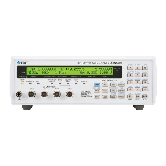
Summary of Contents for NF ZM2376
- Page 1 LCR METER ZM2376 Instruction Manual (Basics) NF Corporation...
- Page 3 DA00042208-005 LCR METER ZM2376 Instruction Manual (Basics)
- Page 4 Registered Trademarks National Instruments and LabVIEW are registered trademarks of National Instruments Corporation in the United States. Other company names and product names used in this Instruction Manual may be trademarks or registered trademarks of respective companies. f...
- Page 5 The scope of this Manual This manual describes the ZM2376 with the firmware version 1.00 or more and CE Marking. Please make sure the CE marking on the rear panel. Please watch the version that appears at the power-on.
- Page 6 The following instruction manuals are provided for ZM2376. ZM2376 Instruction Manual (Basics) This manual describes basic items such as how to operate ZM2376 from the panel, specifications, and maintenance. ZM2376 Instruction Manual (Remote Control) This manual describes how to remote control ZM2376.
- Page 7 ———— Safety Precautions ———— To ensure safe use, be sure to observe the following warnings and cautions. NF Corporation shall not be held liable for damages that arise from a failure to observe these warnings and cautions. This product is a Class I product (with protective conductor terminal) that conforms to the IEC insulation standards.
- Page 8 Do not expose this product to water. When this product is used in wet condition, it may cause an electric shock and a fire. If this product is exposed to water, unplug the power cord immediately, and contact NF Corporation or one of our representatives.
-
Page 9: Table Of Contents
3.5.6.2 Measurement Signal Level ········································································ 3-36 3.5.6.3 Measurement range················································································· 3-37 3.5.6.4 Trigger ·································································································· 3-43 3.5.6.5 Measurement speed ················································································ 3-48 3.5.6.6 Correction of Measurement Error ································································ 3-51 3.5.6.7 OPEN Correction ···················································································· 3-53 3.5.6.8 SHORT Correction ·················································································· 3-59 3.5.6.9 LOAD Correction ····················································································· 3-63 ZM2376... - Page 10 6.6.1 Measurement Frequency Accuracy ····························································· 6-5 6.6.2 Measurement Signal Level Accuracy ··························································· 6-5 6.6.3 Voltage Monitor Accuracy ·········································································· 6-6 6.6.4 DC Bias Voltage Accuracy ········································································· 6-7 6.6.5 AC Impedance Measurement Accuracy ························································ 6-8 6.6.6 DC Resistance Measurement Accuracy ······················································ 6-13 Calibration ······························································································· 6-15 ZM2376...
- Page 11 Table of Contents 7. SPECIFICATION ················································································ 7-1 Specification ······························································································ 7-2 External Dimensions ················································································· 7-17 ZM2376...
- Page 12 Example of external voltage bias circuit ····················································· 4-49 Figure 4-10 Example of external current bias circuit ····················································· 4-51 Figure 7-1 Range of error ······················································································ 7-11 Figure 7-2 LC - Z conversion graph ········································································· 7-12 Figure 7-3 ZM2376 external dimensions ·································································· 7-17 ZM2376 viii...
- Page 13 Table 4–3 Handler interface signal layout ································································· 4-20 Table 4–4 Functions of handler interface signal ························································· 4-21 Table 4-5 Handler interface output in the multi-measurement ······································ 4-34 Table 5-1 When the device appears to be a problem ················································· 5-11 ZM2376...
-
Page 14: 1. Outline
1. OUTLINE 1. OUTLINE ................. 1-1 1.1 Features ................1-2 1.2 Applications..............1-4 1.3 List of Functions ............... 1-5 1.4 Principle of Operation ............1-6 ZM2376... -
Page 15: Features
1.1 Features 1.1 Features The “ZM2376 LCR Meter” is a high speed LCR meter with the maximum frequency 5.5MHz and maximum signal level 5V. It has high basic accuracy of 0.08% and is capable of measuring the impedance in a wide application range from manufacturing and inspection lines of electronic parts up to the research of materials. - Page 16 DC (Direct-current) resistance measurement Direct-current resistance such as a winding resistance of inductor or transformer can be measured. Setting/correction value memory 32 sets of settings and correction values can be stored in nonvolatile memory, and they can be u sed selectively. ZM2376...
-
Page 17: Applications
1.2 Applications 1.2 Applications Inspection, sorting, and evaluation test in production lines of electronic parts such as inductors, capacitors, and sensors. Evaluation and research of magnetic materials and dielectrics. Impedance measurement of batteries. ZM2376... -
Page 18: List Of Functions
1.3 List of Functions 1.3 List of Functions The following shows the functional tree of ZM2376. ZM2376... -
Page 19: Principle Of Operation
1.4 Principle of Operation The ZM2376 gives sine wave signal from an internal oscillator to the DUT (Device Under Test). The impedance bridge detects the current I flowing in DUT and the voltage V applied to DUT, and then the main processor obtains the impedance Z (= V / I). - Page 20 The voltage applied to the DUT is detected by the differential amplifier. After that, the voltage signal and current signal are converted into digital values by the A/D converter, and sent to the main processor. ZM2376...
-
Page 21: 2. Preparations Before Use
2.2 Installation ................. 2-6 2.2.1 General Precautions for Installation ........2-6 2.2.2 Installation Conditions ............2-6 2.2.3 Rack Mounting ............... 2-7 2.3 Grounding and Power Supply Connection ....... 2-12 2.4 Simplified Operation Check ..........2-13 2.5 Calibration ............... 2-14 ZM2376... -
Page 22: Checking Before Use
Check that the instrument has not been damaged during transit. After unpacking, refer to “Table 2-1 Package contents” to check the contents. Table 2-1 Package contents ZM2376 Main Unit ························································· 1 Instruction Manual (Basics) ··············································· 1 CD-ROM (see the next page for the contents) ··························· 1 Power Cord Set (3 Pole, 2 m) ·············································... - Page 23 •IVI (Interchangeable Virtual Instrument) Driver This driver handles the ZM2376 main commands and query. It can be used by various programming languages. LabVIEW can use the IVI driver by importing and converting it to vi or llb.
- Page 24 CAT5 or higher (CAT3 or higher for 10BASE-T). Use a straight cable when connecting to a hub or router which does not have the automatic cable recognition function, or use a cross cable when connecting to a peer PC. ZM2376...
- Page 25 The information given here is as of the preparation of this Instruction Manual. Relevant products are subject to change, abolition, or addition without notice. Be sure to contact NF Corporation or one of our representatives for confirmation when ordering them.
-
Page 26: Installation
Handling of the panel and housing The front panel of ZM2376 is made of plastic. It can be damaged by sharp or hot tools. When the housing/panel surface needs cleaning, wipe with a soft cloth. To remove persistent contamination, wipe with a soft cloth soaked with neutral detergent and wrung out. -
Page 27: Rack Mounting
2.2.3 Rack Mounting ZM2376 can be mounted on a 19-inch IEC rack, an EIA specification rack or a JIS specification rack by the use of a rack-mount adapter (optional). The rack-mount adapter is provided for mm-rack and inch-rack. - Page 28 2.2 Installation Figure 2-1 Rack-mount assembly (mm-rack) ZM2376...
- Page 29 2.2 Installation Figure 2-2 Rack-mount assembly (inch-rack) ZM2376...
- Page 30 2.2 Installation Figure 2-3 Size and dimensions of the rack-mount (mm-rack) ZM2376 2-10...
- Page 31 2.2 Installation Figure 2-4 Size and dimensions of the rack-mount (inch-rack) ZM2376 2-11...
-
Page 32: Grounding And Power Supply Connection
Before connecting the instrument for measurement, make sure the protective grounding terminal is grounded. The protective grounding terminal for ZM2376 is the grounding pin of the three-pole power cord. Make sure you insert the power cord’s plug into a three-pole power outlet with a protective grounding contact. -
Page 33: Simplified Operation Check
Before an important measurement or after a long unused time of instrument, it is recommended to check the ZM2376 operation by the following procedure. Check it within an application range. Plug the power cord in the AC outlet and turn on the power switch on the rear pan el. -
Page 34: Calibration
2.5 Calibration 2.5 Calibration Ensure that ZM2376 undergoes the test described in “6.6 Performance Testing” at least once a year, depending on the use environment and use frequency. It is recommended to conduct a performance test before using it for an important measurement or test. -
Page 35: 3. Panel Features And Basic Operations
3.5.6.3 Measurement range ..........3-35 3.5.6.4 Trigger ..............3-41 3.5.6.5 Measurement speed ..........3-46 3.5.6.6 Correction of Measurement Error ......3-49 3.5.6.7 OPEN Correction ............ 3-52 3.5.6.8 SHORT Correction ..........3-58 3.5.6.9 LOAD Correction ............ 3-62 3.5.6.10 Cable Length Correction ........3-74 ZM2376... -
Page 36: Panel Component Names And Functions
3.1 Panel Component Names and Functions 3.1 Panel Component Names and Functions This section describes the names and functions of the components on the front and rear panel of ZM2376. Register keys Status indicator lamps Correction 0 .. 9 Number Each lamp is lit in the following case. - Page 37 Push up to turn the power on, and push down to Certification label Cooling fan turn it off. air outlet Nomenclature GPIB RS-232 plate connector connector connector connector (Optional) Attached when the LAN option is included Figure 3-2 Rear panel ZM2376...
-
Page 38: Display At Power "On" And Initial Settings
Before connecting the instrument for measurement, make sure the protective grounding terminal is grounded. The protective grounding terminal for ZM2376 is the grounding pin of the three-pole power cord. Make sure you insert the power cord’s plug into a three-pole power outlet with a protective grounding contact. -
Page 39: Displays And Indications At Power "On
BEFORE USE”. When the power switch is turned on, a test pattern is displayed, and then a starting message including the model name and firmware version is displayed (see below). Model name Example: ZM2376 V1.00 2013/10/25 16:27 Version Last adjustment date and time Also, all lamps light up. -
Page 40: Initialization
3.2 Display at Power “ON” and Initial Settings 3.2.3 Initialization ZM2376 is reset to the factory default settings in the following cases: At the time of shipment from factory All settings and correction values including operation modes and memory contents are set to the initial values. - Page 41 Format of correction value G-B|Cp-G <SHORT correction> ← ← ON/OFF OFF|ON ← ← Correction value (Primary & ±9.99999E+11 0, 0 Secondary parameters) Z-equivalent ← ← Format of correction value Rs-X|Ls-Rs Rs-X ZM2376...
- Page 42 ±9.99999E+11, OFF|ON 0,OFF (No Limit) limit (value, ON/OFF) ← ← Secondary parameter lower ±9.99999E+11, OFF|ON 0,OFF (No Limit) limit (value, ON/OFF) ← ← Primary parameter Absolute value| Absolute value comparison format Deviation|Deviation % ZM2376...
- Page 43 × LAN default gateway 0.0.0.0 to 255.255.255.255 0.0.0.0 <Setting/correction value memory> - - Empty × × Content (no saving) ← ← Recall target (at panel Settings|Correction Setting operation) values|Both ZM2376...
- Page 44 It cannot be set/query by the remote control. The followings are out of the resume target: • Measured data saved in the measured data buffer • Latest measured data • Range selected automatically • Measurement parameters selected automatically • Equivalent circuit selected automatically ZM2376 3-10...
-
Page 45: Operation Tree
3.3 Operation Tree 3.3 Operation Tree An operation tree when ZM2376 is operated from the panel is shown below. For the expression of operations, see “3.5.2 Basic Key Operations”. Operation Tree (1/4) _FREQ_: { Measurement frequency setting menu } Frequency selection | { Measurement frequency input menu }... - Page 46 { Upper limit frequency setting menu } _SHIFT_ + [CABLE]: { Cable length correction menu } _SHIFT_ + [CONTACT]: { Contact check setting menu } { Low capacitance check setting menu } { Low capacitance limit setting menu } Continued ZM2376 3-12...
- Page 47 _SHIFT_ + [HANDLER]: { Handler interface setting menu } { OUT OF BINS output setting menu } { Bin extension menu } { Trigger polarity setting menu } { Recall setting menu } { Test menu } Continued ZM2376 3-13...
- Page 48 { Beeper setting menu } { Fully initialization menu } { Settling wait time setting menu } Self-Diagnosis Version display { Operation mode setting menu } _LOCAL_: Shift from remote to the local _SHIFT_ + [KEY LOCK]: Key operation disabled / enabled ZM2376 3-14...
-
Page 49: Connection Of Dut
CAUTION • Do not give signals from outside to the measurement terminals. Do not give signals from outside even when the power is OFF. Otherwise, ZM2376 may be damaged. • Do not connect the charged capacitor. When the DUT could have been charged, discharge the DUT completely before connection. -
Page 50: Connection To Dut
Figure 3-4 Connection to DUT In the measurement of high impedance, shielding around the DUT can restrict variation of measured value. In a simplified method, place an insulating plate on the top surface of ZM2376, and measure the DUT on it. -
Page 51: Precautions On Connection
If cables substantially exceeding the specified length are used, or if DUT to earth capacitance is large, the ZM2376 operation may become unstable or the measurement dispersions may become large due to the influence of resistance value or capacitance of cable inner conductor. Note that particularly the capacitance to ground on the L side is more likely to be influential. - Page 52 Provide an electrostatic shield or keep peripheral potential constant. Be sure to connect the ZM2376 case to the ground. Using 3-pole power cord, connect ZM2376 to the 3-pole power outlet having a protective grounding contact, so that the device is connected to the ground.
-
Page 53: Basic Operations
{Int | Man | Ext | Bus} 4) CORRECTION: OPEN SHORT (Only the enabled corrections are displayed) LOAD Cable length {0m | 1m | 2m | 4m} { } indicates that either one of options delimited with | is displayed. ZM2376 3-19... -
Page 54: Basic Key Operations
_T T T | [BBB] key Indicates the key with TTT written on the key top and BBB written above or under the key. ZM2376 SHIFT SHIFT Tertiary function The tertiary function (BBB) written under the key operates according to the operation flow or situations at that time. - Page 55 For the menu that needs multiple parameters, the parameters to be set can be | [PREV] key and | [NEXT] key. switched with _BS_ _EXP_ Parameter name and current settings Parameter_name: Value1 (Value2) Range of value Comments Available ranges ZM2376 3-21...
- Page 56 ), M (10 If the exponential part is input or the key is pressed again, the exponential part input waiting state is cancelled. ZM2376 EXIT operation With the setting menu, if the ENTR | [EXIT] key is pressed without setting or selecting a value, one-previous menu is returned.
-
Page 57: Initialization
3.5 Basic Operations 3.5.3 Simplified Operating Method When You Use “ZM2376” for the First Time This section describes the simplified operating method when you use the ZM2376 for the first time. Do not connect the handler interface and remote control interface. - Page 58 The options can be switched to those on the second page with the _EXP_ | [NEXT] key. “3.5.5.3 For details Setting of Secondary Parameters” Secondary parameter : D Current setting θ 5)Rs >NEXT Options (first page) 6)Rp 8)Lp 9)Rdc <PREV Options (second page) _CKT_ _Pri_ _Sec_ ZM2376 3-24...
- Page 59 Measurement speed Press the _SPEED_ key to display the measurement speed setting menu, and select the measurement speed with a numeric key. _FREQ_ _LEVEL_ _SPEED_ ZM2376 3-25...
- Page 60 Connect the LCR meter to the DUT by referring to “3.4 Connection of DUT”. Manual trigger _TRIG_ When you set the trigger source to Manual (Man) and press the key, the trigger signal is applied and the measurement is executed once. ZM2376 3-26...
- Page 61 | [INIT] Full initialization To reset all settings except operation modes to the factory default values, perform full initialization. The setting/correction value memory and the multi-measurement list are also initialized. “4.14 Initializing of All Settings” For details ZM2376 3-27...
-
Page 62: Setting Of Measurement Parameters
3.5 Basic Operations 3.5.5 Setting of Measurement Parameters The ZM2376 can display two parameters (primary parameter and secondary parameter) at the same time. In general, L, C, R values are different between series equivalent circuit and parallel equivalent circuit, and therefore select appropriate equivalent circuit according to the nature and circuits used of the DUT. - Page 63 Parameters that can be selected by remote control only By remote control, the followings can be specified, in addition to L, C, R, Z, Y, and G. ZM2376 Instruction Manual (Remote Control) For details :CALCulate1:FORMat command Lp, Ls...
-
Page 64: Setting Of Equivalent Circuit
Z, Y (Don't care) Last value retained Last value retained Rs, Cs, Ls (Don't care) Series Disable Rp, Cp, Lp, G (Don't care) Parallel Disable REAL, MLIN FIMPedance Series Disable FADMittance Parallel Disable AUTO CKT lamp _CKT_ ZM2376 3-30... -
Page 65: Setting Of Secondary Parameters
± (0.00000 - 99999.9) Q, D θ ± (0.000° - 180.000°) Rs, Rp, X, Rdc ± (0.000mΩ - 999.999MΩ) G, B ± (0.00nS - 9.99999kS) ± (0.000nH - 999.999MH) The display range is limited by the measurement range. ZM2376 3-31... - Page 66 Immittance is a concept combining impedance and admittance. DC (Direct-current) resistance Rdc When Rdc is selected, ZM2376 measures the DC resistance after measuring the AC impedance. This function is mainly intended to measure the DC resistance of coil, and is not suited for the measurement of the insulation resistance of capacitor.
-
Page 67: Setting Of Basic Measurement Conditions
Entry: The measurement frequency input menu is as follows. Frequency: 1.00000MHz Current setting 1mHz to 5.50000MHz Available value ranges The setting resolution is 6 digits (1mHz when < 100Hz). If a setting is made or the EXIT operation is performed, one-previous menu comes back. _FREQ_ ZM2376 3-33... -
Page 68: Measurement Signal Level
For the direct-current resistance Rdc, the voltage and current are measured with two measurement signals of about + 1.4V and -1.4V, and Rdc is obtained from a difference of them, regardless of a setting of measurement signal level. ZM2376 3-34... -
Page 69: Measurement Range
If you specify an unavailable range, the device operates with the nearest available range (recommended range, measureable range). The output impedance may be restricted depending on the frequency, signal level, measurement parameters, and CV/CC. (CV: Constant voltage function, CC: Constant current function) ZM2376 3-35... - Page 70 6Ω 1Ω 90mΩ - 1.0Ω - 1.1Ω 6Ω Secondary parameter ≠ Rdc 100mΩ 9mΩ - 100mΩ - 110mΩ 6Ω *2 If the restriction conditions are not met, the operation is the same as when Rd -min = 25Ω-1. ZM2376 3-36...
- Page 71 Rd=100Ω Rd=100Ω Rd=6Ω Rd=6Ω 120Hz 1kHz 120Hz 1kHz 100n 1µ 10µ 100µ Cp F (DUT) Rd: Output impedance Sum of cable resistance, contact resistance, and Rd error (+) = 0.5Ω Figure 3-5 Capacitance to measurement signal level characteristics ZM2376 3-37...
- Page 72 (manual selection). Note that the measurement range of impedance should be lowered when measuring larger capacitance C or admittance |Y|. Perform the EXIT operation to return to the measurement screen. _SHIFT_ _AUTO/HOLD_ | [RANGE] ZM2376 3-38...
- Page 73 When measuring a DUT which has nonlinear voltage-current characteristics, the measured value can be in agreement with the value of an impedance measurement instrument which has an output impedance of 100Ω. Note that the variation may become large when measuring low impedance (small inductance). ZM2376 3-39...
- Page 74 AC impedance measurement range, and normally it is automatically selected. In the remote control, it can be held to specific range. To return to automatic selection by the panel operation, initialize it with the initialize menu. Measurement range of DC (direct-current) resistance RANGE: Manual 100kΩ DC100mΩ Rd:25Ω-100 ZM2376 3-40...
-
Page 75: Trigger
3.5 Basic Operations 3.5.6.4 Trigger The ZM2376 receive a trigger signal to start the measurement. With the trigger setting menu, set the trigger source and measurement sequence. Trigger delay time Trigger delay time Trigger delay time Trigger signal Measurement signal output... - Page 76 Current trigger source is displayed on the second line of measurement screen (in case of status display). • • • • • • A100Ω FAST256 Int OpShLd1m TRIG SOURCE Trigger source: Int / Man / Ext / Bus ZM2376 3-42...
- Page 77 If the DUT is pure capacitance C or inductor L, the signal settles at the time constant C ×Rd or L/Rd where the ZM2376 output impedance is Rd. Make allowance for the settling time of 5 to 7 times the time constant.
- Page 78 Measurement frequency 1kHz Settling time = 1ms + 6 × Rd × C Setting example of trigger delay time (in both cases, Rd=100Ω) Measurement frequency 120Hz, DUT 220µF Trigger delay time 142ms (about 17 periods of signal) Measurement frequency 1kHz, DUT 10µF Trigger delay time 7ms ZM2376 3-44...
- Page 79 Reduction of interference caused by close installation When two or more instruments are installed closely, if the measurement timing is shifted so that the measurement signals do not overlap, the disturbance from other ZM2376 can be reduced. Reduction of variation in short-time measurement Since the measurement start phase of signal is always the same, the variation of measured value becomes small even when the settling time is insufficient.
-
Page 80: Measurement Speed
The measurement time at each frequencies is the time from input of TRIG signal to output of EOM signal through the handler interface when DC resistance is not measured. The values in ( ) at 120Hz and 1kHz express the signal acquisition time with the cycles of the signal. ZM2376 3-46... - Page 81 The measurement range of DC resistance is automatically selected unless the range is held by remote control. The adjustment time of measurement range varies depending on the DC resistance. • Additional time to measure DC resistance “Table 3-4 Example of measurement time” (DC) ZM2376 3-47...
- Page 82 • Automatic range selection time of DC resistance is extended up to about maximum trigger delay time. • Measurement time of DC resistance is extended by about (trigger delay time - 40ms) × 2 when trigger delay time > 40ms. ZM2376 3-48...
-
Page 83: Correction Of Measurement Error
3.5 Basic Operations 3.5.6.6 Correction of Measurement Error The ZM2376 can correct the following errors that will occur by a measurement fixture or connection cable. Zero correction OPEN correction Corrects the error due to the stray admittance that remains when measurement terminals are opened. - Page 84 Only the global correction value is used, and not the spot correction value. SPOT correction If the measurement frequency is equal to the spot correction frequency, the spot correction value is used. Otherwise, the global correction value is used. ZM2376 3-50...
- Page 85 Regardless of the DC bias setting, during the measurement of the OPEN or SHORT correction value, the DC bias is automatically turned off only during that measurement. With the DC bias turned on, the OPEN and SHORT correction values cannot be measured. ZM2376 3-51...
-
Page 86: Open Correction
This can prohibit the correction with unused low frequencies. UppFREQ Displays the upper limit frequency setting menu for the global correction. This can prohibit the correction with unused high frequencies. Perform the EXIT operation to return to the measurement screen. _SHIFT_ | [OPEN] ZM2376 3-52... - Page 87 Same warning message is also displayed when the measurement failed by any reason. Even if this warning message is displayed, the ZM2376 use the obtained measured values as OPEN correction values. However, the previous OPEN correction values are held for the frequencies at which the measurement failed.
- Page 88 Condition for correction : OPEN correction value (|Z|) > SHORT correction value (|Z|) × 2 When the OPEN and SHORT correction values are close, the error will increase unless the LOAD correction is executed. If the ratio is 1000 times or less, it is recommended to execute the LOAD correction. ZM2376 3-54...
- Page 89 At other direct correction points, the correction value is retained without being updated. If the frequency range is extended, measure the correction value again. Otherwise, the interpolated correction value may be incorrect. ZM2376 3-55...
- Page 90 The spot correction will not be disabled in the following cases. • When both the setting and the correction value are recalled (Press _SHIFT_ + [RECALL] and select Both). • When the frequency is changed during the multi-correction. ZM2376 3-56...
- Page 91 Though the warning message will be displayed for the input of correction value of impedance ≤ 1kΩ, it is set as it is as the spot OPEN correction value. If the spot OPEN correction value is zero, the measured value remains as it was before the correction even when the correction is executed. ZM2376 3-57...
-
Page 92: Short Correction
Perform the EXIT operation to return to the measurement screen. The lower and upper limit frequencies set for the global correction are common to the OPEN, SHORT, and LOAD corrections. Lower limit frequency setting menu “3.5.6.7 OPEN Correction” Upper limit frequency setting menu _SHIFT_ | [SHORT] ZM2376 3-58... - Page 93 Same warning message is also displayed when the measurement failed by any reason. Even if this warning message is displayed, the ZM2376 use the obtained measured values as SHORT correction values. However, the previous SHORT correction values are held for the frequencies at which the measurement failed.
- Page 94 If the measurement frequency is changed when the spot correction is enabled, the OPEN, SHORT, and LOAD corrections are all disabled automatically. When you want to execute the spot correction with a new frequency, measure the correction value again. ZM2376 3-60...
- Page 95 Though the warning message will be displayed for the input of correction value of impedance ≥ 900Ω, it is set as it is as the spot SHORT correction value. If the spot SHORT correction value is zero, the measured value remains as it was before the correction even when the correction is executed. ZM2376 3-61...
-
Page 96: Load Correction
It is also possible to change the LOAD standard value later. Cable length OPEN 2-terminal-pair SHORT LOAD circuit network Figure 3-10 Connection circuit network for LOAD correction Typical LOAD correction procedures are described below. ZM2376 3-62... - Page 97 Execute the OPEN correction and the SHORT correction again at the end of the actual connection circuit network. If the correction is performed correctly, almost the same value is obtained as the direct connection even when the measurement is executed at the end of the connection circuit network. ZM2376 3-63...
- Page 98 Connect the standard at the end of the actual connection circuit network and measure the LOAD correction value. The LOAD correction is automatically enabled. Execute the OPEN correction and the SHORT correction again at the end of the actual connection circuit network. ZM2376 3-64...
- Page 99 The lower and upper limit frequencies set for the global correction are common to the OPEN, SHORT, and LOAD corrections. Lower limit frequency setting menu “3.5.6.7 OPEN Correction” Upper limit frequency setting menu The LOAD correction of DC resistance Rdc is not supported. _SHIFT_ | [LOAD] ZM2376 3-65...
- Page 100 When recalling from the setting memory, the OPEN, SHORT, and LOAD corrections are not disabled even if the frequency is changed due to the operation, and the saved settings are restored. Even if the frequency is automatically changed by ZM2376 3-66...
- Page 101 _BS_ | [PREV] or The cursor can be moved between previous and next values by pressing the _EXP_ | [NEXT] key. If a setting is made or the EXIT operation is performed, one-previous menu comes back. ZM2376 3-67...
- Page 102 _BS_ [PREV] or _EXP_ | [NEXT] key. If you specify an extreme value which ZM2376 cannot calculate, an error occurs, and it cannot be set. Perform the EXIT operation to return to one-previous menu. If the spot LOAD correction value is set, the LOAD correction is disabled. To us e the set correction value, enable both the spot correction and the LOAD correction.
- Page 103 Entry >> Spot LOAD correction value input menu CO-LOAD= Cp: +1.02345µF D: +123.456m ±(0.0001p to 999999M) 1.00000kHz If the entered value differs by 20% or more from the standard value, the warning message is displayed as in the case of measuring the correction value. ZM2376 3-69...
- Page 104 Remove the connection circuit network between ZM2376 for the LOAD correction and DUT so as to connect the standard and ZM2376 directly with a cable length of 0m. An additional error should be much smaller than that of the connection circuit network for correction.
- Page 105 If the measurement cannot be executed properly, the previous LOAD standard value is retained, and the following warning message is displayed. Warning: Out of range This warning will disappear when any key is operated or after several seconds have pass ed. ZM2376 3-71...
- Page 106 Connection of standard for LOAD correction. Attach the standard for LOAD correction at the end of the connection circuit network for correction. Actually used connection circuit network Standard / OPEN / SHORT Figure 3-12 Measurement of LOAD correction value ZM2376 3-72...
- Page 107 DUT measurement. Even if the obtained LOAD correction value is out of the range of "standard value ±20%", the LOAD correction is executed based on the standard value and the obtained correction value. ZM2376 3-73...
-
Page 108: Cable Length Correction
3.5.6.10 Cable Length Correction The cable length correction corrects an additional error due to the connection cable between ZM2376 and DUT. ZM2376 uses coaxial cables of impedance 50Ω (cable capacitance = about 105pF/m) and the length of four cables must be same. If the cables have different characteristics, the correction cannot be performed correctly. -
Page 109: 4. Advanced Operations
4.13 Changing the Settling Wait Time During Automatic Adjustment ..............4-55 4.14 Initializing of All Settings ..........4-56 4.15 Self-Diagnosis ............... 4-59 4.16 Checking the Version ............. 4-60 4.17 Remote Control ............. 4-61 4.18 Switching the Operation Mode (alternative command) ... 4-62 ZM2376... - Page 110 (voltage with the H terminal opened) is displayed at the bottom right. The measurement error depends on this signal level. Note that the measurement error can increase at a low signal level. _SHIFT_ _LEVEL_ | [ALC] ZM2376...
- Page 111 Current: The current setting menu is as follows. Current: 1.00mA Current setting 0.0010mA to 200mA Available value ranges The setting resolution is 3 digits (0.1µA when < 10µA). If a setting is made or the EXIT operation is performed, one-previous menu comes back. ZM2376...
- Page 112 There are the following other restrictions. Due to the characteristic variations of ZM2376, the voltage or current may not be adjusted to settable maximum voltage or maximum current.
- Page 113 ≤1kHz, ≥40mA Rd=6Ω 1.2V Rd=25 Rd=100Ω can be used only when 25Ω Z≤1Ω (L≤159µH) 10mV 10mV 25Ω 100µ 10µ 100µ 100m 電流 Arms Current Arms Figure 4-2 Inductance range measurable at constant voltage (supplementary value) ZM2376...
-
Page 114: Restricting The Variation Of Measured Value (Averaging)
Even if the measurement speed is RAP or FAST, increase the averaging count, so that the measurement accuracy achieved when measurement speed is MED can be used when the signal acquisition time of MED is exceeding. ZM2376... -
Page 115: Displaying The Deviation From The Reference Value
If a setting is made or the EXIT operation is performed, one-previous menu comes back. When the deviation or deviation% is selected, the “∆” displayed in front of measured value of primary parameter. ∆Cp:+ 23.456 % D:+0.12345 1.00000k _SHIFT_ _Pri_ | [∆Pri] ZM2376... - Page 116 If a setting is made or the EXIT operation is performed, one-previous menu comes back. When the deviation or deviation% is selected, the “∆” displayed in front of measured value of secondary parameter. Cp:+12.3456µF ∆D :+0.12345 1.00000k _SHIFT_ _Sec_ | [∆Sec] ZM2376...
- Page 117 For both primary and secondary parameters, even if either display or comparator is set up, the same display format or comparison format or reference value is obtained. ZM2376...
-
Page 118: Sorting The Part (Comparator)
4.4 Sorting the Part (Comparator) 4.4 Sorting the Part (Comparator) For ZM2376, up to 14 bins for primary parameter and one set range for secondary parameter can be set to sort the comparison results. Limit comparison The remote control allows the use of limit comparison function wherein sorting is done while upper/lower limit (one set) of primary parameter and upper/lower limit (one set) of secondary parameter are being set. - Page 119 • • The secondary parameter is larger than the upper limit. The secondary parameter is within the upper/lower limit range or comparison for secondary parameter is not conducted. The secondary parameter is less than lower limit. ZM2376 4-11...
- Page 120 When the comparator function is enabled, the COMPRTR lamp on front panel lights up. It also lights up when the limit comparison function is enabled. COMPRTR lamp _SHIFT_ | [COMPRTR] | [Pri/Sec] | [NO LIMIT] _EXP_ | [SYSTEM] ZM2376 4-12...
- Page 121 ±(0.0000p to 999999M) Available value ranges _EXP_ + [µ] keys for instance, decides by Enter the numeric value and the exponential part input ENTER key. If a setting is made or the EXIT operation is performed, one-previous menu comes back. ZM2376 4-13...
- Page 122 All upper limit values 0,OFF Sorting for BIN1 (Value, ON/OFF) (No Limit) All lower limit values 0,OFF Sorting for BIN2 to BIN14 (Value, ON/OFF) (No Limit) Comparison of secondary parameter ------ The display format and comparison format are not initialized. ZM2376 4-14...
- Page 123 ±(0.0000p to 999999M) Available value ranges Move the cursor to the point of parameter you need to set (mentioned later) and set the value. The unit depends on each parameter. Perform the EXIT operation to return to one-previous menu. ZM2376 4-15...
- Page 124 "OUT OF BINS”. Measured value Measured value BIN1 BIN2 BIN3 OUT OF BINS Small Large Small Large (a) When overlapped (b) When there is a clearance Figure 4–4 Range setting and comparison when sorting into bins ZM2376 4-16...
- Page 125 Lo:+1.23456µF Hi:+1.23456µF Lo:+10.0000µ Hi:+1.23456m When switched from secondary parameter into primary parameter (BIN), the cursor moves to the lower limit value of BIN1. Lo:+10.0000µ Hi:+1.23456m BIN1 ON Lo:+1.23456µF Hi:+1.23456µF _SHIFT_ | [Pri/Sec] _BS_ | [PREV] _EXP_ | [NEXT] ZM2376 4-17...
- Page 126 Note that, even if range comparison is set to “Enable(ON)”, it cannot be sorted for the given Bin in case of lower limit value ≥ upper limit value. Substantially the comparison for upper/lower limit value is not conducted. ZM2376 4-18...
- Page 127 Bin is disabled. Once both of lower and upper limit values for the secondary parameter are disabled, it becomes the same state as is the case when the range comparison of secondary parameter is disabled. _SHIFT_ | [NO LIMIT] ZM2376 4-19...
- Page 128 IN or be regarded as “FAIL” in other cases. After setting, the results are displayed for a short time and return to one-previous menu. Perform the EXIT operation to return to one-previous menu. _SHIFT_ _EXP_ | [SYSTEM] ZM2376 4-20...
-
Page 129: Connecting To The Part Handler (Handler Interface)
4.5 Connecting to the Part handler (Handler Interface) 4.5 Connecting to the Part handler (Handler Interface) For the ZM2376, the comparator result can be output into the handler interface of rear panel. Connecting to the part handler allows auto part sorting system to be configured. - Page 130 Internal DC power output (common) It is connected to the enclosure. To operate the Handler interface with the 46 ~50 INT COM Internal DC power source, make connection between EXT COM and INT COM and also between EXT DCV and INT DCV. ZM2376 4-22...
- Page 131 Otherwise, you may feel an electric shock. ! CAUTION Do not apply the voltage more than 42Vpk onto the signals or common of handler interface versus case. Otherwise, the ZM2376 may be damaged. Handler interface I/O equivalent circuit EXT DCV EXT DCV EXT DCV 3.3k...
- Page 132 The output immediately after power turned on is the same as above as well. Also, the same state is established by the initializing operation with the initialize menu or system setting menu or by the *RST command. Regardless of enabled/disabled of comparator, input of handler interface is always enabled. •Input: TRIG, /KEY_LOCK,/RCL0/RCL6,/RCL-VALID ZM2376 4-24...
- Page 133 In case of S-NG, “OUT OF BINS” signal is not output. Exclude When primary parameter is within the range but secondary parameter is outside the range, it should be classified as the independent AUX Bin (S-NG) instead of “OUT OF BINS”. ZM2376 4-25...
- Page 134 If a setting is made or the EXIT operation is performed, one-previous menu comes back. The Trigger polarity cannot be selected in Remote control. Also, it cannot be initialized with the *RST command or the initialize menu by the _SHIFT_ + [INIT] key operation. ZM2376 4-26...
- Page 135 When you try to recall them from the memory with no data saved, an error occurs. For multi-channel correction, ZM2376 supports up to 32 channels. For channels more than 32, you can read and save the spot correction value of each channel with remote control, and then write it...
- Page 136 When ON is selected, the output signal is initialized to the state when the comparator is disabled. The test signal is operated with BIN/ERR/EOM on the menu. ZM2376 ignores the input signal and operates as if nothing is connected to the handler interface. Lock by /KEY_LOCK signal is also released.
- Page 137 Changes /INDEX and /EOM as shown in the Mm (status of EOM) 5)EOM figure below. m = 0 : High level m = 1 : Low level Approx 10ms /INDEX /EOM Nearly simultaneously Approx 1ms Figure 4–7 Dummy output timing ZM2376 4-29...
-
Page 138: Measuring With More Than One Condition (Multi-Measurement)
Measure step-by-step at each trigger. It is useful to read the measurement value at each step. Entry Displays the multi-measurement list input menu. If a setting is made or the EXIT operation is performed, the measurement screen comes back. _SHIFT_ _FREQ_ | [LIST] ZM2376 4-30... - Page 139 When it is set to OFF, the content of the setting memory is held. When the setting memory numbers are OFF (initial value) in all steps, only the frequency is switched. When the setting memory number is specified to 0 to 31, the setting is recalled before the ZM2376 4-31...
- Page 140 When no valid spot correction value is saved in the correction value memory, the current global correction value (and standard value) is used for correction. Unlike usual measurement, the OPEN/SHORT/LOAD correction is not disabled in each step even when the frequency changes. ZM2376 4-32...
- Page 141 Limit comparison ••• “4.4 Sorting the Part (Comparator)”, “4.5 Connecting to the Part handler (Handler Interface)”, and separate manual “ZM2376 Instruction Manual (Remote Control)” :CALCulate:COMParator[:STATe] Command In the multi-measurement, the limit comparison is performed on the upper/lower limit values of the primary parameter (BIN1) and the upper/lower limit values of the secondary parameter for each step.
- Page 142 Total secondary parameter fail comparison signal All measurement is normal, primary parameters are passed, but any of secondary parameters is failed. The other output signals are fixed to the high level. Input signal is always enabled with or without multi-measurement. ZM2376 4-34...
- Page 143 Figure 4-8 Handler interface operation timing in the multi-measurement In the step mode, the DUT can be changed per step. For example, you can measure components of a composite part with conditions suitable for each of them in sequence. ZM2376 4-35...
- Page 144 2) Trigger delay time In each step, the signal acquisition starts at the trigger delay time after the setting and correct ion value are recalled. 3) Contact check The contact check and low capacitance check are performed in each step. ZM2376 4-36...
-
Page 145: Changing The Contents Displayed On The Second Line Of
Even if P-S REF is selected, the status appears when the deviation display and deviation comparison are disabled. Current/voltage monitor value • • • Im:+123.456mA Vm:+1002.34mV Z- Impedance measured value • • • Z:+123.456kΩ :+ 1.567° _AUX DISP_ ZM2376 4-37... - Page 146 BIN No:14 Current setting 1 to 14 Available value ranges To display the upper/lower limit values of primary parameter, set the Bin number. Perform the EXIT operation to return to one-previous menu. After setting, measurement screen comes back. ZM2376 4-38...
-
Page 147: Memory
4.8 Saving/Recalling the Setting and Correction Value 4.8 Saving/Recalling the Setting and Correction Value ZM2376 saves/recalls the setting and correction value up to 32-set. Saving the setting and correction value into the memory _SHIFT_ + [ SAVE ] _SHIFT_... - Page 148 The contents of setting/correction value memory cannot be initialized by the key. It is possible to initialize the setting/correction value memory by the operation of “Fully initialization” in system setting menu. However, the setting of interface is also initialized. Fully initialization “4.14 Initializing of All Settings”. ZM2376 4-40...
-
Page 149: Setting The Contact Check
The contact check and low capacitance check provided by ZM2376 do not give an additional error to measured values. An additional time to the measurement can be ignored. - Page 150 4.9 Setting the Contact Check Operational outline of contact check The contact check of ZM2376 is a simple type which detects mainly a contact failure of H terminal in 4-terminal connection. The contact check of ZM2376 can be used in the following ranges.
- Page 151 When a low capacitance is measured due to a contact failure, it is regarded as Low C (abnormal low capacitance) in ZM2376. Exactly, it is regarded as Low C when an impedance higher than the impedance corresponding to the specified capacitance is detected.
-
Page 152: Applying The Dc Bias Voltage
4.10 Applying the DC Bias Voltage 4.10 Applying the DC Bias Voltage ZM2376 allows the measurement where DC bias voltage up to 5V is applied on polar capacitance, PN junction of semiconductor and etc. It is also possible to compensate the electromotive force of battery to measure the impedance. - Page 153 BIAS Restriction between signal level and bias voltage The peak voltage that can be output by ZM2376 is approx 7.07V. It is impossible to set when the total of the peak value of AC measurement signal and DC bias voltage exceeds the above voltage.
- Page 154 ZM2376 fine adjusts the DC cancel amount at the voltage sensing section in the range of the DC bias voltage ± 0.25V when the auto DC cancel function is enabled. However, it takes time to adjust. When the auto DC cancel function is disabled, the cancel amount is equal to the set value of the bias voltage.
- Page 155 In the DC bias setting menu, select AUTO. ZM2376 fine adjusts the DC bias voltage in the range of the set value ± 0.25V so that the DC current at the L terminal is approx zero when the auto DC balance function is enabled.
- Page 156 When leaving the actual electromotive force and the DC bias voltage differ significantly, a large current may continue flowing to deteriorate ZM2376 and the battery. As with the battery, a charged EDLC (Electric double layer capacitor) with big capacity can be measured.
- Page 157 H terminal and H terminal so that the DC voltage and current may not run through the LCR meter. Set the DC bias output of ZM2376 to OFF. DC bias Voltage source DC blocking circuit...
- Page 158 C2, and the voltage sensing circuit of the LCR meter temporarily saturates to disable the measurement. ! WARNING Use the bias voltage within the following range: (|Bias voltage[V]|+ 1.41 × Measurement signal level[Vrms]) < 42[V] Otherwise, it may cause an electric shock. ZM2376 4-50...
-
Page 159: Applying The Dc Bias Current
DUT. The LCR meter may be damaged due to a high voltage caused by the disconnected DUT. Set the protective diode. The rectifier diode, which has a serge current susceptibility for preventing from damaging due to the bias current and also has a small reverse leak ZM2376 4-51... - Page 160 When an external power is connected, measured values may vary by noise mixing like ripple current. Also, the capacitance to grounding may increase (the impedance to grounding decreases), and the measurement error increases or the operation is unstable to disable the measurement. In these ZM2376 4-52...
- Page 161 Fix to a measurement range not prone to cause a measurement error. Increase the measurement signal level of the LCR meter or decrease the output impedance. Decrease the measurement speed and also use averaging. ZM2376 4-53...
-
Page 162: Disabling The Key-Operation Of Panel
The /KEY_LOCK signal is disabling all key-operation. Also in this case, the KEY LOCK lamp lights up. Locking by the /KEY_LOCK signal cannot be canceled by the panel operation or remote control interface. Only when the /KEY_LOCK signal is set to “0” (high level), it can be canceled. ZM2376 4-54... -
Page 163: Changing The Settling Wait Time During Automatic Adjustment
Available value ranges _ENTR_ _EXP_ + [m] Enter the numeric value and use the key or the exponential part input keys. If a setting is made or the EXIT operation is performed, one-previous menu comes back. _SHIFT_ _EXP_ | [SYSTEM] ZM2376 4-55... -
Page 164: Initializing Of All Settings
4.14 Initializing of All Settings 4.14 Initializing of All Settings ZM2376 can be initialized in some levels. Initializing the current setting while the contents of setting/correction value memory are being left over _SHIFT_ + [ INIT ] _SHIFT_ + [INIT] keys to display the initializing menu. - Page 165 After execution, the completion message appears for a short time and measurement screen comes back. _SHIFT_ _EXP_ | [SYSTEM] In the remote control, it is possible to initialize only 1), 2), and 3) described above. • • • the separate manual “ZM2376 Instruction Manual (Remote Control)” :SYSTem:RST command ZM2376 4-57...
- Page 166 4.14 Initializing of All Settings Initializing the operation mode ZM2376 provides more than one operation mode. The operation mode cannot be initialized by the above two initializing operations. To initialize the operation mode, set the operation mode to the default value. Set the operation mode in the following orders.
-
Page 167: Self-Diagnosis
4.15 Self-Diagnosis 4.15 Self-Diagnosis The self-diagnosis function for analog measurement circuit is built in the ZM2376. This function automatically runs at power-on, besides you can use it at your option. _SHIFT_ + [ SYSTEM ] _SHIFT_ + [SYSTEM] keys to display the system setting menu. -
Page 168: Checking The Version
4.16 Checking the Version 4.16 Checking the Version The version number of ZM2376 firmware (built-in control software) is displayed after power-on. You can also check it in the system setting menu. _SHIFT_ + [ SYSTEM ] _SHIFT_ + [SYSTEM] keys to display the system setting menu. -
Page 169: Remote Control
ZM2376 can be remotely controlled by USB or RS-232 and GPIB. LAN is available optionally. For more information, refer to the separate manual “ZM2376 Instruction Manual (Remote Control)”. The separate manual is included in the attached CD-ROM. The setting of remote control interface is made from the system setting menu. -
Page 170: Switching The Operation Mode (Alternative Command)
4.18 Switching the Operation Mode (alternative command) 4.18 Switching the Operation Mode (alternative command) ZM2376 can change the remote control commands by switching the operation mode. 1) Operation mode 0: Standard operation mode Use the standard command for remote control. - Page 171 Operation mode 0 • • • • • • • 1.00000k • • • • • • • 1.00 V Operation mode 1 • • • • • • • 1.00000k • • • • • • • 1.00 V Underline ZM2376 4-63...
-
Page 172: 5. Troubleshooting
5.1.1 Errors at Power ON .............. 5-3 5.1.2 Errors at Panel Operation ............. 5-4 5.1.3 Errors During Measurement ..........5-5 5.1.4 Measured Value Display in Case of Error ......5-6 5.2 When the Device Appears to be a Problem ....... 5-7 ZM2376... -
Page 173: Error Message
When the repair is required, please contact NF Corporation or one of our representatives. When you request the repair of ZM2376, please let us know the content of an error message if it is displayed. An error message not listed in this instruction manual may be displayed due to a malfunction caused by strong external noise. -
Page 174: Errors At Power On
Configuration System settings such as GPIB address memory lost have been lost. •Defective memory •Temporary failure due to power off, etc. during data processing ZM2376... -
Page 175: Errors At Panel Operation
7Vpeak) because DC bias voltage is output. Memory error Contents of setting/correction value Re-save the contents. memory are lost. Since there are other error messages and warning messages not listed here, see the description of respective operations. ZM2376... -
Page 176: Errors During Measurement
2) Cooling fan is defective. 2) Please ask NF Corporation or one of our representatives for repair. •Though overheat was detected, the Over Press the... -
Page 177: Measured Value Display In Case Of Error
Switch to proper measurement range. (OVerFlow) display range. Measured value may be displayed by changing the type of parameters. In the remote control, the measured value is output within the specified range of remote control, regardless of the display. ZM2376... -
Page 178: When The Device Appears To Be A Problem
When the device appears to be a problem, check the following table to see if a corrective action is given. When the problem persists or the device cannot be recovered though a corrective action was taken, please contact NF Corporation or one of our representatives. Table 5-1 When the device appears to be a problem 1/4... - Page 179 If discharge is made to measurement terminals, the defective connection cables. measurement signal source, voltage detector, or current detector may be damaged. Check the cables for disconnection, or the inner and outer conductors for short-circuit. ZM2376...
- Page 180 Do not connect the DUT’s terminal to the ground. It The L side of DUT is grounded. Or, DUT is grounded with low can be checked with a multimeter. ZM2376 cannot impedance. measure the grounded DUT. This is also true for the measurement of correction values.
- Page 181 HOLD. selection function. The settling wait time with the automatic selection The measurement range is not enabled can be adjusted depending on the situation. determined due to a noise or contact failure. ZM2376 5-10...
-
Page 182: 6. Maintenance
6.6.1 Measurement Frequency Accuracy ........6-5 6.6.2 Measurement Signal Level Accuracy ........6-5 6.6.3 Voltage Monitor Accuracy ............ 6-6 6.6.4 DC Bias Voltage Accuracy ........... 6-7 6.6.5 AC Impedance Measurement Accuracy ....... 6-8 6.6.6 DC Resistance Measurement Accuracy ......6-13 6.7 Calibration ............... 6-15 ZM2376... -
Page 183: Preface
Check if the device operates properly. •Performance Testing: Check if the device respects the rated values. •Adjustment, calibration: If the rated values are not satisfying, NF Corporation will make the necessary adjustment or calibration to restore performance. •Damage repairs: When performance cannot be restored by the adjustment or calibration, NF Corporation will identify the cause and location of the damage and will execute repairs. -
Page 184: Daily Maintenance
It is also possible to read out the version by means of *IDN? (Query). ZM2376 Instruction Manual (Remote Control) “5.3.1 Common Commands” NF Corporation may offer a new improved version without notice. Please check our Web site and update if necessary. http://www.nfcorp.co.jp/ When turning the power on, also check the displayed test pattern (full dot display pattern) and all lamps being lit. -
Page 185: Checking Isolation
Set the multimeter to diode test mode (test current 1mA), and measure between the outer conductor of each BNC connector on front panel of ZM2376 and the ground terminal (case) at bottom left. Make sure that the voltage is within the range stated below. When out of this range, it might be possibly damaged. -
Page 186: Measurement Frequency Accuracy
If the values indicated on AC voltmeter are within the specification range in table, it is normal. Measurement frequency 1kHz (initial value) Measurement signal Values indicated on AC voltmeter level Specification: ± (8% + 5 mVrms) 0.1Vrms 87m to 113mVrms 1Vrms 0.915 to 1.085Vrms 5Vrms 4.595 to 5.405Vrms ZM2376... -
Page 187: Voltage Monitor Accuracy
Values indicated on AC voltmeter level Specification: ±(2% + 2mVrms) Monitor Specification: ± 4.0mVrms mVrms 0.1Vrms Voltmeter Difference: mVrms mVrms Monitor Specification: ± 0.022Vrms Vrms 1Vrms Voltmeter Difference: Vrms Vrms Monitor Specification: ± 0.102Vrms Vrms 5Vrms Voltmeter Difference: Vrms Vrms ZM2376... -
Page 188: Dc Bias Voltage Accuracy
0.000 V -0.0050 V to +0.0050 V 1.000 V -1.0250 V to -0.9750 V DC bias voltage 2.500 V -2.555 V to -2.445 V 5.000 V -5.105 V to -4.895 V CAUTION: The polarity is inversed due to the connection. ZM2376... -
Page 189: Ac Impedance Measurement Accuracy
6.6 Performance Testing 6.6.5 AC Impedance Measurement Accuracy Described here is the easy checking method. For the correct test, request NF Corporation to make test. Standard: To make correct test, prepare a 4-terminal-pair standard with approximately 1/3 or less in calibration accuracy against the accuracy of ZM2376. Described here is an example of test where easy-to-available standard is used. - Page 190 D ± 0.0010 Ω Ω Z ± 0.16 % 10Ω 10Ω θ θ θ θ ± 0.093 ° ° ° ° Ω Ω Z ± 0.25 % 1Ω 1Ω θ θ θ θ ± 0.14 ° ° ° ° ZM2376...
- Page 191 Ω Ω Z ± 0.23 % 10Ω 10Ω θ θ θ θ± 0.13 ° ° ° ° For the 1k, 10k, and 100k ranges, either a standard resistor or a standard capacitor should be used for the test. ZM2376 6-10...
- Page 192 ° ° Ω Ω Z ± 1.6 % 100Ω 100Ω θ θ θ θ ± 0.91 ° ° ° ° Ω Ω Z ± 2.3 % 10Ω 10Ω θ θ θ θ ± 1.3 ° ° ° ° ZM2376 6-11...
- Page 193 1000pF D ± 0.0022 Measurement signal level 5Vrms, Measurement frequency 1MHz, Cable length 0m Difference Standard Calibration value of Measurement Measured value 100×(B-A)/A (nominal standard Specification range value) % C ± 1.9 % 1kΩ 100pF D ± 0.019 ZM2376 6-12...
-
Page 194: Dc Resistance Measurement Accuracy
Standard: To make correct test, prepare a 4-terminal-pair standard with approximately 1/3 or less in calibration accuracy against the accuracy of ZM2376. For the measurement of low resistance, a 4-terminal connection is required to avoid an effect from contact resistance. - Page 195 Since it is impossible to fix by manual, press the _SHIFT_ + [RANGE] keys to display the Measurement range setting menu, check the measurement range of DC resistance, and then check the measurement accuracy at that measurement range. ZM2376 6-14...
-
Page 196: Calibration
6.7 Calibration 6.7 Calibration If the performance test does not satisfy the specification, NF Corporation will make the necessary adjustment or calibration to recover the performance. If necessary, contact NF Corporation or one of our representatives. You will be liable for the costs of adjustment and calibration outside the warranty period. - Page 197 7. SPECIFICATION 7. SPECIFICATION .............. 7-1 7.1 Specification ..............7-2 7.2 External Dimensions ............7-16 Supplementary value: These values show the guideline data for reference guarantee performance. ZM2376...
- Page 198 0 F, ± (0.00001pF to 99.9999kF) • L (Ls, Lp) 0 H, ± (0.00001nH to 9.99999GH) • Q, D 0, ± (0.00001 to 99999.9) • ±180.000 ° Actual measurement and display ranges of respective parameters are restricted by the measurement range or frequency. ZM2376...
- Page 199 Setting range 0s to 999.9999s, Resolution 0.0001s (Time after input of trigger until start of signal acquisition) • Triggered drive Drive only at measurement / Continuous drive selectable (Measurement signal can be output only during the time from trigger to completion of signal acquisition) ZM2376...
- Page 200 It should be an appropriate trigger delay time and not zero. Additional time when measuring direct-current resistance (supplementary value) FAST SLOW VSLO (DC) 150ms 150ms 150ms 218ms 616ms Conditions: DC resistance measurement range fixed, Trigger delay time = 0, Averaging count = 1. ZM2376...
- Page 201 The output impedance may be restricted depending on the frequency and signal level. When cable length = 4m and frequency > 200kHz, the measureable range is limited to between 10 and 10k ranges. • Measurement range selection Auto / Manual ZM2376...
- Page 202 If the measureable range for the 10 range becomes unlimited depending on the minimum output impedance setting, the following values should be used. Zx / Zr (however, 1 when Zx / Zr < 1) > 10Ω ≤ 10Ω Zr / Zx (however, 1 when Zr / Zx < 1) ZM2376...
- Page 203 0.50 0.50 0.60 0.50 0.50 100mΩ 1.00 1.00 The measurement accuracy is not guaranteed for "---". Ω range The basic coefficient A of the 100 is increased 1.5 times, when the output impedance is 25Ω or 6Ω below 1MHz. ZM2376...
- Page 204 10 times of the value shown below. Frequency range Ky [%] DC, Frequency ≤ 50kHz Zx[Ω] / ( 2 × 10 50kHz < Frequency ≤ 500kHz Zx[Ω] × (Frequency[kHz]) / (2 × 10 500kHz < Frequency Zx[Ω] / ( 1× 10 ZM2376...
- Page 205 2.01 100kΩ 4.00 1.00 0.10 0.10 0.15 10kΩ 4.00 1.00 0.10 0.10 0.15 1kΩ 0.80 0.10 0.10 0.30 100Ω 0.20 0.05 0.05 0.50 10Ω 0.20 0.05 0.05 0.10 1Ω 0.10 0.01 0.01 0.01 0.20 100mΩ 0.20 0.10 0.01 0.01 ZM2376...
- Page 206 10Ω 0.05 0.05 0.05 0.20 0.50 1Ω - - - 0.20 0.20 0.50 0.50 100mΩ - - - - - - - - - - - - - - - The measurement accuracy is not guaranteed for "---". ZM2376 7-10...
- Page 207 Dx = tan(c) x: 0180° c: ± 90° ± Az / cos(x) [%] ± Az / cos(x) [%] × Measurement frequency[Hz]. Suffix “x” of a parameter indicates a measured value. = 2 × Figure 7-1 Range of error ZM2376 7-11...
- Page 208 × Frequency[Hz] × L[H] |Z|[] = 2 × × Frequency[Hz] × C[F]) |Z|[] = 1 / (2 × Approximate value can be read from the following graph. Frequency Frequency Figure 7-2 LC - Z conversion graph ZM2376 7-12...
- Page 209 Rated power voltage: External +5V to +24V, Internal +5V (non-isolated) • Multi-measurement Execute measurement and limit comparison under multiple conditions for the total comparison. Maximum number of steps: 32 Selectable measurement conditions: Measurement frequency, measurement signal level, internal DC bias voltage, measurement parameters, etc. ZM2376 7-13...
- Page 210 For the data rate exceeding 19200bps, communication may fail depending on the characteristics of cable or controller. Flow control None, Software (X-ON/X-OFF), Hardware (RTS/CTS) • GPIB Conforms to IEEE 488.1 and IEEE 488.2 Standards • LAN (optional) 10BASE-T / 100BASE-TX, RJ-45 connector ZM2376 7-14...
- Page 211 32 sets. Settings and correction values can be saved and restore individually or together. • Resume Last setting and correction value are restore at power-on. • External dimensions Approx. 260 (W) × 88 (H) × 280 (D) mm, not including protuberances • Weight Approx. 2.4kg (without accessories) ZM2376 7-15...
- Page 212 7.2 External Dimensions 7.2 External Dimensions Figure 7-3 ZM2376 external dimensions ZM2376 7-16...
- Page 213 NF or an agent designated by NF. Purchaser shall prepay shipping charge, duties and taxes for the product to either NF or the agent from another country, and shipping charge for the return of the product to purchaser shall be paid by NF side.
- Page 215 However, we assume no responsibility for any damage regarding the contents of the instruction manual. If you have any uncertainty or you found an error or omission, please contact NF Corporation or one of our representatives from which you purchased the product.
- Page 218 NF Corporation http://www.nfcorp.co.jp/ 6-3-20 Tsunashima Higashi, Kohoku-ku, Yokohama 223-8508 JAPAN...
Need help?
Do you have a question about the ZM2376 and is the answer not in the manual?
Questions and answers