Table of Contents
Advertisement
Quick Links
Advertisement
Table of Contents

Subscribe to Our Youtube Channel
Related Manuals for NF FRA5022


Summary of Contents for NF FRA5022
- Page 1 FREQUENCY RESPONSE ANALYZER FRA5022 Instruction Manual NF Corporation...
- Page 3 DA00016981-005 FREQUENCY RESPONSE ANALYZER FRA5022 Instruction Manual...
- Page 4 Registered Trademarks National Instruments is a registered trademark of National Instruments Corporation in the United States. Other company names and product names may be trademarks or registered trademarks of their respective companies.
- Page 5 ――― Preface ――― Thank you very much for purchasing our “FRA5022 FREQUENCY RESPONSE ANALYZER”. To ensure safe and proper use of this electric equipment, please read first “Safety Precautions”on the following pages. ● Caution Symbols Used in This Manual The following caution symbols are used in this manual. Be sure to observe these caution symbols and their contents to ensure the safety of the user and avoid damage to the equipment.
- Page 6 ――― Safety Precautions ――― To ensure safe use, be sure to observe the following warnings and cautions. NF Corporation shall not be held liable for damages that arise from a failure to observe these warnings and cautions. This product is a Class I product (with protective conductor terminal) that conforms to the JIS and IEC insulation standards.
- Page 7 Shows when connected to the case. Shows when connected to the ground. ● Note on Waste Processing To protect the environment, ensure that this device is disposed of by an appropriate industrial waste processor. Also note the following: ・This device includes lithium batteries. FRA5022...
-
Page 8: Table Of Contents
3.5.5 Sweep Menu Screen ..................3-20 3.5.6 Spot Menu Screen ................... 3-27 3.5.7 Sweep Measurement ..................3-30 3.5.8 Sweep Measurement Screen ................3-31 3.5.9 Spot Measurement ..................3-32 3.5.10 Spot Measurement Screen ................3-33 3.5.11 Measured Values of Excessive Input ............. 3-34 FRA5022... - Page 9 5.5.2 Command Detailed Explanations ..............5-11 5.6 Status System ......................5-33 5.6.1 Status System Overview ................. 5-33 5.6.2 Status Byte ...................... 5-34 5.6.3 Standard Event Status ..................5-35 5.6.4 Operation Status ....................5-37 5.6.5 Overload Status ....................5-39 5.7 Programming Cautions ..................5-40 FRA5022...
- Page 10 8.1 Oscillator ........................8-2 8.2 Analyzer Input ......................8-3 8.3 Analysis Processor ....................8-3 8.4 Measurement Processing ..................8-4 8.5 Display Part ......................8-5 8.6 Settings Memory ...................... 8-5 8.7 Remote Control Interface ..................8-5 8.8 General Information ....................8-6 FRA5022...
- Page 11 Figure 4-4 Oscillator setup screen (ex.) ................4-3 Figure 4-5 Evaluation result display .................. 4-6 Figure 4-6 Scan measurement ..................4-7 Figure 4-7 Connection for servo system measurement ............. 4-9 Figure 4-8 Measurement voltage range magnification example........4-11 Figure 4-9 Connection with equalizer ................4-13 FRA5022...
- Page 12 Table 3-1 Setting items and initial values ................3-7 Table 4-1 Setup items and screen handling ..............4-4 Table 5-1 FRA5022 subsystem command list ..............5-4 Table 5-2 Common command list ..................5-7 Table 5-3 Status byte register definitions ................ 5-34 Table 5-4 Standard event status register contents ............
-
Page 13: 1. Outline
1. OUTLINE 1.1 Features ······················································ 1-2 1.2 Applications ·················································· 1-2 1.3 List of Functions ············································ 1-3 1.4 Principle of Operation ····································· 1-5 FRA5022... -
Page 14: Features
1.1 Features Features “FRA5022 Frequency Response Analyzer” allows you to obtain the frequency response characteristics (change of gain and phase vs frequency) of a system under test by supplying sine wave signals to the system under test and by analyzing the response signals. -
Page 15: List Of Functions
Gain passing range upper limit Gain passing range lower limit Phase passing range upper limit Phase passing range lower limit Scan Measurement settings Measurement mode CH2/CH1 CH2/OSC Integration time Integration cycle Delay time Data memory control Display mode A&B Store to memory B FRA5022... - Page 16 HOLD OSC OFF Settings memory Settings title Settings lock Settings initialization Settings copy One touch switching System Self calibration Total initialization Scan upper limit Automatic scan Error reset Switch to LOCAL Interface Interface selection GPIB GPIB address Serial No. FRA5022...
-
Page 17: Principle Of Operation
(Sin, Cos) to be used by the oscillator or analyzer. • Oscillator The FRA5022 oscillator converts digital sine signals to analog signals with D/A (Digital to Analog) converters and filters. It also adds DC bias before output. FRA5022... - Page 18 (the signal vectors) by multiplication and integration of the response signal with orthogonal reference signals (Sin, Cos). This process allows to attenuate frequency components that do not match the signal frequency and thus render possible accurate measurements even with considerable noise. FRA5022...
-
Page 19: 2. Preparations Before Use
2.2 Installation ···················································· 2-3 2.2.1 General Precautions for Intallation ················ 2-3 2.2.2 Installation Conditions ································ 2-3 2.2.3 Rack Mounting ········································· 2-4 2.3 Grounding and Power Supply Connection ··········· 2-9 2.4 Simplified Operation Check ···························· 2-10 2.5 Calibration ·················································· 2-11 FRA5022... -
Page 20: Checking Before Use
・ Data display software ・ LabVIEW driver ・ Sample program The data display software allows you to easily import the data from FRA5022 to a personal computer, save data in CSV format, display data as various graphs, and set main parameters. -
Page 21: Installation
■ Handling of the panel and case The front panel of FRA5022 is made of plastic. It can be damaged by sharp or hot tools. When the case/panel surface needs cleaning, wipe with a soft cloth. To remove persistent contamination, wipe with a soft cloth soaked with neutral detergent and wrung out. -
Page 22: Rack Mounting
2.2 Installation 2.2.3 Rack Mounting FRA5022 can be mounted on a 19-inch IEC rack, an EIA specification rack or a JIS standard rack by the use of a rack-mount adapter (optional). First, mount the rack-mount adapter on the device as shown in “Fig. 2-3 Mounting rack-mount adapter (mm-rack)”... - Page 23 2.2 Installation Figure 2-1 Size and dimensions of the rack-mount (mm-rack) FRA5022...
- Page 24 2.2 Installation Figure 2-2 Size and dimensions of the rack-mount (inch-rack) FRA5022...
- Page 25 ・ Remove the screws on the sides of the front panel (2 each). ・ Use the screws supplied with the rack-mount adapter. Figure 2-3 Mounting rack-mount adapter (mm-rack) Figure 2-3 Mounting rack-mount adapter (mm-rack) Figure 2-4 Mounting rack-mount adapter (inch-rack) FRA5022...
- Page 26 2.2 Installation Figure 2-5 Removal of feet FRA5022...
-
Page 27: Grounding And Power Supply Connection
■ Power Supply ! CAUTION To ensure that FRA5022 is not damaged, make sure to connect to the power outlet after checking that the power voltage is within the specified range for the FRA5022. FRA5022 operates with the following commercial power supply. -
Page 28: Simplified Operation Check
AC amplitude changed. ・Lastly, change the amplitude to 1Vrms and press the ON AC/DC key. 7. Branch the output from OUT OSCILLATOR of FRA5022 to the INPUT CH1 and INPUT CH2 terminals. Since the signal input/output is isolated from the case, connect the three signal ground conductors together. -
Page 29: Calibration
・After the sweep is complete, check the graph. Calibration Ensure that FRA5022 undergoes the test described in “7.7 Performance Testing” at least once a year, depending on the use environment and use frequency. It is recommended to conduct a performance test before using it for an important measurement or test. - Page 30 2-12 FRA5022...
-
Page 31: 3. Panel Features And Basic Operations
3.5.5 Sweep Menu Screen ······························· 3-20 3.5.6 Spot Menu Screen ·································· 3-27 3.5.7 Sweep Measurement ······························ 3-30 3.5.8 Sweep Measurement Screen ···················· 3-31 3.5.9 Spot Measurement ································· 3-32 3.5.10 Spot Measurement Screen ····················· 3-33 3.5.11 Measured Values of Excessive Input ········· 3-34 FRA5022... -
Page 32: Panel Component Names And Functions
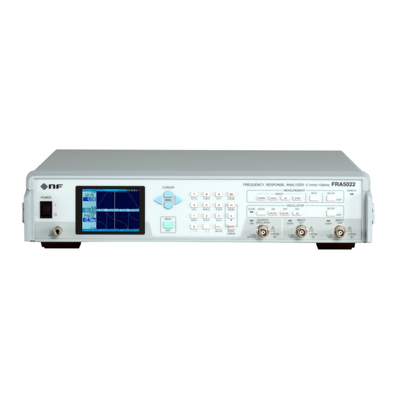
3.1 Panel Component Names and Functions Panel Component Names and Functions This section describes the names and functions of the components on the front and rear panels of FRA5022. FRA5022... - Page 33 0 to the set number. OVER lamps turns on when pk/rms: When setting AC amplitude, it is possible to switch units in Vpeak (pk) or Vrms. input is excessive. Figure 3-1 Front panel FRA5022...
- Page 34 3.1 Panel Component Names and Functions Handle Nomenclature plate Certification label GPIB connector USB connector Cooling fan outlet Power inlet AUX connector Provides ±24V power to the signal injector probe 5055. Figure 3-2 Rear panel FRA5022...
-
Page 35: Display At Power "On" And Initial Settings
・ Connect the power cord to the power inlet at the back of the device. ・ Insert the power cord's plug to a three-pole power socket. ・ By switching the power switch upward the FRA5022 is turned on. When the device is turned on the start screen is displayed and self calibration starts. After self calibration has ended it is possible to use FRA5022 for measurements. -
Page 36: Displays And Indications At Power "On
Upon turning on the power switch, a sound is emitted and the device model name “FRA5022” as well as version number are displayed. All the lamps are lit for a short span of time. During this time, various checks, including memory self check are executed. In case of problem, the following error messages are displayed. - Page 37 180.0deg ✓ phase max Graph phase -360.0 to 359.9 display min -180.0deg ✓ phase min Spot phase display minimum value -360.0 to 0.0 deg -180.0deg ✓ spot phase min ✓: set to initial values Blank: no change FRA5022...
- Page 38 Quick only ✓ / Slow enable slow on/off Interface Connection method GPIB / USB GPIB INTERFACE connect GPIB address 0 to 30 address (measurement Sweep/Spot Sweep --- screen) Output on/off on/off ✓: set to initial values Blank: no change FRA5022...
-
Page 39: I/O Terminals
50Ω. When the device is powered on and then off, the output terminal becomes open for a short duration. ! CAUTION Even when the power is off, do not apply an external signal. Applying a voltage exceeding 5V can damage FRA5022. OUTPUT OSCILLATOR 50Ω 50Ω... -
Page 40: Analyzer Input Terminal
Do not apply a signal that exceeds the non-destructive maximum input voltage. Otherwise, FRA5022 may be damaged. ■ Input when the power is turned off When the device is powered off or waiting to be ready for measurement after power-on, the input terminals as well as the external conductor (ground) are isolated from the internal parts. -
Page 41: Signal Terminal Isolation
Other connector’s core conductor (signal) conductor (signal) 42Vpk 42Vpk Case Case Figure 3-5 Insulation voltages of input and output terminals ! CAUTION Do not connect the isolated parts to a signal that exceeds 42Vpk. Otherwise, FRA5022 may be damaged. 3-11 FRA5022... -
Page 42: I/O Connection
Shield Voltage clamp Figure 3-6 Connection with the system under test (SUT) It is possible to use the FRA5022 front panel grounding terminal as the SUT's ground or shield. ■ CH1 Input internal connection When the oscillator output OSCILLATOR is used with the analyzer input CH1 it is possible to make the connection inside FRA5022. -
Page 43: Basic Operations
3.5 Basic Operations Basic Operations 3.5.1 Simplified Sweep Measurement This section describes simplified operations when first using FRA5022. It describes as frequency sweep and a measurement of a system's frequency response. Proceed according to the following procedure. 1) Initialization: executed to simplify understanding of the following steps. -
Page 44: Setup Screen, Measurement Screen Switchover
Oscillator setup screen MEAS SETUP SETUP SETUP Sweep setup screen Spot setup screen EXIT (measurement screen) System menu screen Sweep menu screen Spot menu screen CURSOR Setup screen Figure 3-8 Setup screen, measurement screen switchover (description) 3-14 FRA5022... -
Page 45: Menu Screen Basic Operation
■ Menu screen switchover The menu screen has three sub-menus that are switchable with the Left/Right cursor key. • System menu screen: Settings related to remote control and FRA5022 in general • Sweep menu screen: Settings related to sweep measurements •... - Page 46 Confirm the entry by pressing the ENTR key. ■ Error messages handling When the set values exceed the possible range, an error message is displayed. The message can be dismissed by pressing the ENTR/RESET ERROR key. Dismiss the message after checking its contents. 3-16 FRA5022...
-
Page 47: System Menu Screen
3.5 Basic Operations 3.5.4 System Menu Screen Items that are common to FRA5022 as a whole, or remote control items can be setup in the System menu screen. Three sub-menus: switchable with the Left/Right cursor keys M E N U < S Y S T E M > < S W E E P > < S P O T >... - Page 48 SLOW lamp illuminates and the AC amplitude and DC bias of the output changes linearly within a duration of up to 10 seconds. Pressing the QUICK key is allowed only once, to linearly change the output. Initial values: 0) Quick only 3-18 FRA5022...
- Page 49 ■ Serial Number Serial Number Description: Serial number for the FRA5022 model. This value cannot be modified. The value is necessary to identify the device when a connection to FRA5022 is made through USB. ■ Initialize all INITIALIZE all...
-
Page 50: Sweep Menu Screen
Value range: 0 - 9 Description: FRA5022 can use 10 individual settings memories. The settings in the sweep screen are not limited to changing the settings of the actual measurements but can also be registered in the specified setting memories. - Page 51 The output DC bias of the oscillator. When the output terminal is open this is the value that is used. Changes in this value will not be reflected until the Output ON AC/DC key is pressed. Initial values: 0V 3-21 FRA5022...
- Page 52 When the system under test exhibits some latency due to high order filters or the like, accurate measurement cannot be obtained unless sufficient time is allowed before the response is stabilized. Initial values: 0.00 s 3-22 FRA5022...
- Page 53 Value range: 0) Auto 1) Manual Description: Auto: Measures at all the specified frequency points by changing the frequency automatically. Manual: Measures at one point with each press of one of the DOWN/HOLD/UP keys. Initial values: 0) Auto 3-23 FRA5022...
- Page 54 Displays the gain as a complex number expression a+jb, where a is the real part and b is the imaginary part. Graphs are always displayed as a Bode diagram (GdB, P-F), regardless of the above settings. Initial values: 0) GdB, P-F 3-24 FRA5022...
- Page 55 Value range: -360.0 to 359.9deg Description: Graph (Bode diagram) minimum value for the phase axis. Initial values: -180.0deg The phase value is displayed within a range from the set graph phase minimum value to that value plus 359.99 deg. 3-25 FRA5022...
- Page 56 0 to 9 : Setting memory number Description: Copies the contents of the currently displayed setting memory to another setting memory. If the displayed memory is locked, the copy target will become free. If the target memory is locked the copy is not possible. 3-26 FRA5022...
-
Page 57: Spot Menu Screen
For the details, refer to the descriptions of the sweep measurement screen. □ Setting memory selection: SETTING memory □ Setting memory title: TITLE □ Oscillator frequency: OSC frequency □ Oscillator AC amplitude: OSC ac amplitude □ Oscillator DC bias: OSC dc bias 3-27 FRA5022... - Page 58 Sets the phase minimum value. The phase range is “minimum value” to “minimum value+359.99 deg”. □ CH1 Excessive input detection level: OVER level ch1 □ CH2 Excessive input detection level: OVER level ch2 □ Operation with excessive input: OVER response 3-28 FRA5022...
- Page 59 When maximum value ≦ minimum value, no evaluation is made and the result is positive. Result evaluation details “4.3 Result Evaluation” □ Setting memory protection: SETTING lock □ Setting memory individual initialization: SETTING clear □ Setting memory contents copy: SETTING copy to 3-29 FRA5022...
-
Page 60: Sweep Measurement
Preesing the MENU key or SETUP key displays the setup screen. While the setup screen is displayed, sweep measurement is paused and no measurement is performed. After the settings are changed, the previous measurement data will be displayed until a new measurment is started. 3-30 FRA5022... -
Page 61: Sweep Measurement Screen
When many frequency points are clustered and cannot be resolved, using the UP cursor key allows you to magnify the frequency axis near the cursor by 1×/2×/4× /8×/16×. Use the Up/Down cursor keys (MAG) to magnify/reduce the display as needed. 3-31 FRA5022... -
Page 62: Spot Measurement
(sequential measures when HOLD). Sequential measures can be stopped by pressing the STOP key. To resume, press the SPOT key. During the measurement, the Repeat status at the top left of the spot measure screen blinks. 3-32 FRA5022... -
Page 63: Spot Measurement Screen
“4.3 Result Evaluation” ■ About amplitude display It is possible to monitor the signal's amplitude from FRA5022’s spot measurement screen. The amplitude measurement value is the RMS value of the measured frequency’s fundamental wave (sine wave). In FRA, the noise components that differ from the measured frequency are not measured. -
Page 64: Measured Values Of Excessive Input
When the input signal to the analyzer CH1 or CH2 exceeds the measurement range (±10V), the gain obtained will be displayed as the maximum value that can be displayed on FRA5022. Below are the actual values displayed: ・ Gain (dB): +199.99dB... -
Page 65: 4. Advanced Operations
4.4.1 Scan Related Setup Items ·························· 4-7 4.4.2 Scan Measurements Operation and Function · 4-7 4.5 Servo System Measurement ···························· 4-9 4.6 Data Memory ·············································· 4-12 4.7 Equalizer ···················································· 4-13 4.8 Oscillator Output Terminal Change Rate Limit (SLOW) ····················································· 4-14 FRA5022... -
Page 66: Setup Screen
■ Graph Y-axis automatic scaling: DISP scale ■ Graph gain maximum value: DISP gain max ■ Graph gain minimum value: DISP gain min ■ Graph phase maximum value: DISP phase max ■ Graph phase minimum value: DISP phase min FRA5022... -
Page 67: Spot Setup Screen
The setup items for the oscillator setup screen are a sweep menu and spot menu screen subset, as shown below. ■ Oscillator frequency: OSC frequency ■ Oscillator AC amplitude: OSC ac amplitude ■ Oscillator DC bias: OSC dc bias FRA5022... -
Page 68: Settings Memory
Settings Memory 4.2.1 Setting Memory Description FRA5022 can keep 10 settings groups in its setting memory. The memory contents is backed up by the battery and is not erased when it has been turned off. During a measurement, it is possible to press a numerical key (0 to 9) to select the corresponding setting. -
Page 69: Setting Memory Operation
SETTING copy to Copies the contents of the currently displayed setting memory to another setting memory. If the displayed memory is locked, the copy destination will be unlocked (free). If the copy destination is locked, copying results in an error. FRA5022... -
Page 70: Result Evaluation
When the evaluation result is either OVER or UNDER, the item name is displayed in red. 2:TITLE Repeat Freq 1.0000kHz Gain (dB) ▲Gain -77.15dB evaluation result ▼Phase -123.45deg Phase evaluation result CH2/OSC 0.100mVrms (OSC) CH1 723.5mVrms D: 0.10s I:10c/ 1.00s OSC:1.0000kHz 7.07Vrms +0.00Vdc Figure 4-5 Evaluation result display FRA5022... -
Page 71: Scan Measurement
Setting memory n: Scan maximum k/▼ key (m/SCAN key) k/▼ key (m/SCAN key) Setting memory 2 k/▼ key (m/SCAN key) Setting memory 1 k/▼ key (m/SCAN key) Setting memory 0 m/SCAN キー Figure 4-6 Scan measurement FRA5022... - Page 72 The output will be immediately change as if per QUICK, even if SLOW is set. Even after a scan measurement is over, the oscillator's output will remain ON and the AC amplitude and DC bias will remain at their last values. FRA5022...
-
Page 73: Servo System Measurement
4.5 Servo System Measurement Servo System Measurement It is possible to obtain the servo system loop gain Aβby inserting FRA5022 oscillator into a control loop and to measure the signal’s V and V before and after. SUT : System Under Test... - Page 74 5055 Signal Injector/Probe. Details about 5055 conditions of use or measurement are found in the 5055 Instruction Manual. 5055 can get its power supply from FRA5022 rear panel’s AUX connector. 5055 comes with 2 different FRA connection cables. Use the one that connects to the AUX connector.
- Page 75 4.5 Servo System Measurement ■ Measurement voltage range magnification FRA5022’s internal oscillator has a dialectic voltage of 42Vpk against the case. It is thus possible directly input a signal with an electric potential of up to about ±40V to the circuit.
-
Page 76: Data Memory
4.6 Data Memory Data Memory FRA5022 has two measurement results storage memories (data memory A, data memory The latest measured data is always put to data memory A. The following data memory operations are possible. <System menu screen> ■ Measurement data recording STORE data A-->B... -
Page 77: Equalizer
A/B may vary even if the data in the data memory A is consistent. The analyzer input capacitance of FRA5022 has a slight voltage dependency. For this reason, equalizing may not be effective in reducing errors when the signal source impedance or frequency is high. -
Page 78: Oscillator Output Terminal Change Rate Limit (Slow)
In case the output changes abruptly due to shocks during a vibration test, etc., the system under test can be damaged. To prevent this, it is possible to slowly change FRA5022’s oscillator output voltage. ・Use the MENU key to display the menu screen, select <SYSTEM> tab with the Left/Right cursor keys ・Use the Up/Down cursor keys... -
Page 79: 5. Remote Control
5.5.2.2 Subsystem Commands ······················· 5-15 5.6 Status System ············································· 5-32 5.6.1 Status System Overview ·························· 5-32 5.6.2 Status Byte ············································ 5-33 5.6.3 Standard Event Status ····························· 5-34 5.6.4 Operation Status ···································· 5-36 5.6.5 Overload Status ····································· 5-38 5.7 Programming Cautions ·································· 5-39 FRA5022... -
Page 80: Preparations Before Use
GPIB card/controller board. 5.1.3 Remote Control Interface Selection In FRA5022 it is possible to select GPIB or USB as remote control interface. It is not possible to use GPIB and USB simultaneously. Select either one from the system menu screen. -
Page 81: Usb Device Identification
5.1.5 GPIB Address Setting With GPIB the system devices are identified by a device- specific address. Each device must be setup with a unique GPIB address. The GPIB address for FRA5022 can be set via the system menu screen. Items: INTERFACE address Value range: 0 - 30 5.1.6 Necessary Precautions When Using GPIB... -
Page 82: Command List
The FRA5022 subsystem commands are show in table 5-1. Common commands supported by FRA5022 are shown in table 5-2. The meaning of codes used in table 5-1 and table 5-2 are explained below. It is possible to omit the keywords lower case parts. - Page 83 5.3 Command List Table 5-1 FRA5022 subsystem command list 2/3 Function Command SENSe subsystem Sweep measurement data :SENSe:DATA:SWEep[:DATA]? readout Sweep measurement points :SENSe:DATA:SWEep:POINt? readout Spot measurement data readout :SENSe:DATA:SPOT[:DATA]? Spot gain evaluation maximum :SENSe:DATA:SPOT:LIMit:GAIN:MAXimum Spot gain evaluation minimum :SENSe:DATA:SPOT:LIMit:GAIN:MINimum Spot phase evaluation...
- Page 84 5.3 Command List Table 5-1 FRA5022 subsystem command list 3/3 Function Command STATus subsystem Operation condition register STATus:OPERation:CONDition? Operation event enable register STATus:OPERation:ENABle Operation event register STATus:OPERation[:EVENt]? Operation transition filter (1 → 0) STATus:OPERation:NTRansition Operation transition filter (0 → 1)
- Page 85 *STB? Status byte query Queries the status byte. *TST? Self-test query Queries the self diagnosis results. *In FRA5022, 0 is always returned. Wait to continue command Waits until all the overlapped commands have *WAI been processed before executing later commands.
- Page 86 ■ Device Clear The device clear function (DCL, SDC) for interface allows you to: ・ Clear the input buffer ・ Clear the output queue ・ Clear the waiting for overlapped command completion using *WAI, *OPC, or *OPC? FRA5022...
-
Page 87: Command Tree
5.4 Command Tree Command Tree The FRA5022 subsystem command tree is shown on figure 5-1. CALibration [ALL] DISPlay COORdinates DATA MEMory STORe PHASe MINimum WINDow SCALe MODE TRACe GAIN MAXimum MINimum PHASe MAXimum MINimum INPut{1|2} VOLTage OVERload [LEVel] RESPonse MEASure... -
Page 88: Command Explanation
It is possible to use both simultaneously. Ex.) :DISPlay:COORdinates? → :display:coordinates? Acceptable (lower case) Acceptable :DISP:coor? (mixed upper/lower case) Not Acceptable (wrong :DISPL:COOR? intermediary abbreviated form) Not Acceptable (omission :DISP:COO? over-abbreviated) 5-10 FRA5022... -
Page 89: Command Detailed Explanations
→ :SOUR:FREQ:SWE:LEV:MAX 12.3kHz :FREQ:SWE:MAX 12.3kHz 5.5.2 Command Detailed Explanations The function and syntax of all the commands shown in “Table 5-1 FRA5022 subsystem command list” and “Table 5-2 Common command list” are explained below. 【Meaning of symbols】 ・Keywords shown in square brackets ([ ]) are those that support omission (implicit keywords) ・Curly braces ({ }) indicate parameters in the command string. -
Page 90: Standard Event Status
“5.6.3 Standard Event Status” Query example: *ESR? Response example: *IDN? Description: Queries the model name etc. Parameters: None Response: Contents “name of manufacturer, model name, serial number, firmware version” format <SRD> Query example: *IDN? Response example: “NF Corporation,FRA5022,9025257,Ver1.00” 5-12 FRA5022... - Page 91 <setting_memory> memory number, format <NR1>, range 0 to 9 Settings example: *SAV 5 *SRE <srq_enable> Description: Sets the service request enable register. Parameters: <srq_enable> register contents, format <NR1>, range 0 to 255 Details “5.6.1 Status System Overview” Example: *SRE 128 Response: <srq_enable> 5-13 FRA5022...
- Page 92 5.5 Command Explanation Query example: SRE? Response example: 5-14 FRA5022...
- Page 93 *STB? Response example: *TST? Description: Queries the self diagnosis results. Parameters: None Response: In FRA5022, “0” is always returned format <NR1> Query example: TST? Response example: *WAI Description: Waits until all the overlapped commands have been processed before executing later commands. Refer to the explanations below.
- Page 94 <NR1>, range 0/1/2/3 0: A, 1: B, 2: A&B, 3: A/B Settings example: DISP:DATA:MEM 0 Response: <data_memory> Query example: DISP:DATA:MEM? Response example: :DISPlay:DATA:STORe Description: Copies the latest measurement data (data memory A contents) to data memory B. Parameters: None Example: DISP:DATA:STOR 5-16 FRA5022...
- Page 95 Response example: 120.0 :DISPlay:WINDow:TRACe:GAIN:MINimum <gain_min> :DISPlay:WINDow:TRACe:GAIN:MINimum? Description: Sets/queries the graph gain dB minimum value. Parameters: <gain_min> dB minimum, format <NR2>, range -180.0 to 179.9 [unit dB] Settings example: DISP:WIND:TRAC:GAIN:MIN -120.0 Response: <gain_min> Query example: DISP:WIND:TRAC:GAIN:MIN? Response example: -120.0 5-17 FRA5022...
- Page 96 It is not possible to set a Bode diagram frequency axis magnification ratio with the remote control interface. ■ Cursor displacement speed It is not possible to set the cursor displacement speed with the remote c ontrol interface. 5-18 FRA5022...
- Page 97 :INPut:VOLTage:OVERload:RESPonse <over_response> :INPut:VOLTage:OVERload:RESPonse? Description: Sets/queries the process when excessive input is detected. Parameters: <over_response> response format <NR1>, range 0/1/2/3 0: Lamp, 1: Beep. 2: Hold, 3: Off Settings example: INP:VOLT:OVER:RESP 1 Response: <over_response> Query example: INP:VOLT:OVER:RESP? Response example: 5-19 FRA5022...
- Page 98 <integ_time> Query example: MEAS:INT:TIME? Response example: 999.99 :MEASure:MODE <mode> :MEASure:MODE? Description: Sets/queries the measurement mode. Parameters: <mode> measurement mode, format <NR1>, range 0/1 0: CH2/CH1, 1: CH2/OSC Settings example: MEAS:MODE 0 Response: <mode> Query example: MEAS:MODE? Response example: 5-20 FRA5022...
- Page 99 Settings example: MEAS:SPOT:REP ON Response: <spot_repeat>, format <NR1>, range 0/1 0: single, 1: repeat Query example: MEAS:SPOT:REP? Response example: ■ Scan measurement It is not possible to conduct the operations related to scan measurement with the remote control interface. 5-21 FRA5022...
- Page 100 The allowed characters are the same as those allowed when inputting from the panel. Lower case characters can be used during the setting but they will be converted to upper case characters. Settings example: MEM:TIT 1, “TEST(1-2)” Response: <title> Query example: MEM:TIT? 1 Response example: “TEST(1-2)” 5-22 FRA5022...
- Page 101 :SENSe:DATA:SPOT:LIMit:GAIN:MAXimum <gain_upper_limit> :SENSe:DATA:SPOT:LIMit:GAIN:MAXimum? Description: Sets/queries the spot measurement gain evaluation upper limit. Parameters: <gain_upper_limit> Gain evaluation upper limit format <NR2>, range -199.99 to 199.99 [unit dB] Settings example: SENS:DATA:SPOT:LIM:GAIN:MAX 120.00 Response: <gain_upper_limit> Query example: SENS:DATA:SPOT:LIM:GAIN:MAX? Response example: 120.00 5-23 FRA5022...
- Page 102 Parameters: None Response: <gain_class>,<phase_class> gain evaluation result, phase evaluation result format <NR1>, <NR1> range -1/0/1 -1: NG if less than the lower limit/ 0: GO /1: NG if more than the upper limit Query example: SENS:DATA:SPOT:LIM:REP? Response example: 5-24 FRA5022...
- Page 103 Response: When displaying A, A/B, B <NR1> When displaying A&B <NR1>, <NR1> For details of each value, refer to the description above. Query example: SENS:DATA:SWE:POIN? Response example: 1000 When displaying A, A/B, B 1000, 1000 When displaying A&B 5-25 FRA5022...
- Page 104 Response: <measure_operation> Query example: SWE:MEAS? Response example: [:SOURce]:SWEep:MODE <operation_mode> [:SOURce]:SWEep:MODE? Description: Sets/queries the sweep operation mode. Parameters: <operation_mode> operation mode, format <CRD>, range AUTO | MANual Settings example: SWE:MODE AUTO Response: <operation_mode> Query example: SWE:MODE? Response example: AUTO 5-26 FRA5022...
- Page 105 SWE:MAX? Response example: 100.00E+03 [:SOURce]:SWEep[:LEVel]:MINimum <freq_min> [:SOURce]:SWEep[:LEVel]:MINimum? Description: Sets/queries the sweep measurement minimum frequency. Parameters: <freq_min> minimum frequency, format <NR3>, range 0.10E-3 to 99.999E+03 [unit Hz] Settings example: SWE:MIN 0.0001 Response: <freq_min> Query example: SWE:MIN? Response example: 0.10E-03 5-27 FRA5022...
- Page 106 Each value corresponds to the ON AC/DC key on the panel. Set to 1 puts AC to OFF and keeps DC in its previous state Settings example: VOLT:OUTP 0 Response: <output_state> displays status according to each operation. Query example: VOLT:OUTP? Response example: 5-28 FRA5022...
- Page 107 7.07 [:SOURce]:VOLTage:UNIT <amplitude_unit> [:SOURce]:VOLTage:UNIT? Description: Sets/queries the oscillator AC amplitude display unit and response unit. Parameters: <amplitude_unit> AC amplitude unit, format <CRD>, range VRMS | VPK Settings example: VOLT:UNIT VRMS Response: <amplitude_unit> Query example: VOLT:UNIT? Response example: VRMS 5-29 FRA5022...
-
Page 108: Operation Status
STAT:OPER:ENAB 0 Response: <opee> Query example: STAT:OPER:ENAB? Response example: STATus:OPERation[:EVENt]? Description: Queries the operation event register (OPER). Parameters: None Response: Register contents, format <NR1>, range 0 to 32767 Details・・・ “5.6.4 Operation Status” Query example: STAT:OPER? Response example: 5-30 FRA5022... -
Page 109: Overload Status
<ovee> Query example: STAT:OVER:ENAB? Response example: 0 STATus:OVERload [:EVENt]? Description: Queries the overload event register (OVER). Parameters: None Response: register contents, format <NR1>, range 0 to 32767 Details・・・ “5.6.5 Overload Status” Query example: STAT:OVER? Response example: 0 5-31 FRA5022... - Page 110 Description: Releases the error just like RESET ERROR key from the front panel. Example of released error ・Input signal exceeds measurement possible voltage range ・User set excessive input detection level is exceeded ・Output overload Parameters: None Example: SYST:OVER:REL 5-32 FRA5022...
- Page 111 5.6 Status System Status System 5.6.1 Status System Overview The status system for FRA5022 is shown on figure 5-2. Operation status Operation condition register Positive/negative transition filter Standard event status Overload status Operation event register Standard event status register Overload event register...
- Page 112 Cannot be cleared by any other commnad. Cleared to 0 upon powering on. The parameter value of the setting message or response message to each register is the sum of the weight of all the bits having 1 as the value. 5-34 FRA5022...
- Page 113 Set to 1 when a readout has been attempted on an empty response message output buffer or when the response message output buffer data has been lost. Request control Always at 0 (unused) Operation complete Set to 1 when the all the overlapped command process have been completed. 5-35 FRA5022...
- Page 114 Cannot be cleared by any other command. Cleared to 0 upon powering on. The parameter value of the setting message or response message to each register is the sum of the weight of all the bits having 1 as the value. 5-36 FRA5022...
- Page 115 5.6.4 Operation Status The operation status structure is shown on figure 5-4. As can be seen on table 5-5, the operation condition register displays FRA5022’s status. When a positive transition filter register bit is set to 1, the corresponding state changes from 0 to 1 and the operation event register bit is set to 1.
- Page 116 ■ Related commands / queries STATus:OPERation:CONDition? Queries the operation condition register contents. The condition register content is not cleared to 0 even if queried. Always indicates the status of FRA5022. STATus:OPERation:NTRansition / STATus:OPERation:NTRansition? Sets/queries the negative transition filter register. STATus:OPERation:PTRansition / STATus:OPERation:PTRansition? Sets/queries the positive transition filter register.
- Page 117 5.6.5 Overload Status The overload status structure is shown on figure 5-5. As can be seen on table 5-6, the overload event register displays FRA5022’s input/output status. When the overload event enable register bits are set to 1, the corresponding overload event register bits become valid.
-
Page 118: Programming Cautions
LF or END. However, some drivers may not work properly unless you specify separately that LF or END should follow the command. In some cases, line feed may be referred to as new line, but they have the same binary code. 5-40 FRA5022... - Page 119 5-41 FRA5022...
-
Page 120: 6. Troubleshooting
6. TROUBLESHOOTING 6.1 Error Messages ············································· 6-2 6.1.1 Errors at Power-On ··································· 6-2 6.1.2 Error During Panel Operation ······················ 6-3 6.1.3 Remote Control Errors ······························· 6-3 6.2 When Fault Symptoms are Observed ················· 6-4 FRA5022... -
Page 121: Error Messages
・Backup battery is empty will be necessary to make ・Backup memory fault repairs. Contact NF ・Temporary internal data error Corporation or one of our due to power-off, etc. while representatives. operating on the memory... -
Page 122: Error During Panel Operation
“Too many errors” Error queue overflow, new errors will not -350 be maintained <FRA5022 specific error> Max and min have been reversed when “Invalid parameter (max<=min)” -370 setting a graph display range, etc. The oscillator output voltage peak value is “OSC ad+dc >... -
Page 123: When Fault Symptoms Are Observed
6.2 When Fault Symptoms are Observed When Fault Symptoms are Observed If you found a malfunction, try the following actions. If the problem persists, contact NF Corporation or one of our representatives. Contents Possible cause Solution Power supply The power supply used is... -
Page 124: 7. Maintenance
7.7.1 Frequency Accuracy Test ······························ 7-4 7.7.2 Oscillator AC Amplitude Accuracy Test ············ 7-4 7.7.3 Oscillator DC Bias Accuracy Test ··················· 7-4 7.7.4 Ratio Accuracy Test ····································· 7-5 7.7.5 IMRR Test ················································· 7-6 7.7.6 Dynamic Range Test ··································· 7-6 7.8 Calibration ······················································ 7-7 FRA5022... -
Page 125: Introduction
The following maintenance is essential for using the device under the best condition. ・Operation inspection: Check if the device operates properly. ・Performance testing: Check if the device respects the rated values. ・Adjustment, calibration: If the rated values are not satisfying, NF Corporation will make the necessary adjustment or calibration to restore performance. -
Page 126: Checking Version Number
7.4 Checking Version Number Checking Version Number The version number of your FRA5022 is displayed after power-on for a few seconds at the center of the screen under the model name. The version number can be retrieved by using the query “*IDN?”. -
Page 127: Frequency Accuracy Test
Evaluation: Correct if within the bellow specification range. SPECIFICATIONS DC bias ±(0.5% of the set absolute value +30mV) setting +10V +9.920V - +10.080V +4.945V - +5.055V +0.965V - +1.035V -0.030V - +0.030V -1.035V - -0.965V -5.055V - -4.945V -10.080V - -9.920V -10V FRA5022... -
Page 128: Ratio Accuracy Test
Measurement: For each AC amplitude, press the DOWN or UP key and execute a sweep measurement. Evaluation: Correct if within the following range. With Frequency ≦ 20kHz Gain 0±0.05dB / Phase 0±0.3° With Frequency > 20kHz Gain 0±0.15dB / Phase 0±1° FRA5022... -
Page 129: Imrr Test
Keep the noise source at a distance and conduct the tests. Evaluation: Correct if tested CH1 gain > 120dB, tested CH2 gain < -120dB. Example of CH1 dynamic range test Input short circuit OSCILLATOR Coaxial cable FRA5022... -
Page 130: Calibration
7.8 Calibration Calibration If the performance test does not produce satisfying results, NF Corporation will make the necessary adjustment or calibration to restore performance. If calibration is necessary, contact NF Corporation or one of our representatives. You will be liable for the costs of adjustment and calibration outside the warranty period. - Page 131 FRA5022...
-
Page 132: 8. Specifications
8.2 Analyzer Input ·············································· 8-3 8.3 Analysis Processor ······································· 8-3 8.4 Measurement Processing ······························· 8-4 8.5 Display Part ·················································· 8-5 8.6 Settings Memory ············································ 8-5 8.7 Remote Control Interface ································· 8-5 8.8 General Information ········································ 8-6 Values without accuracy (range) are typical values. FRA5022... -
Page 133: Oscillator
It is possible to limit the output variation rate to output both AC/DC with a slow variation ⚫ Isolation Insulation voltage: 42Vpk or 30Vrms, DC to 100kHz continuously From/to one another among oscillator output (signal, ground), analyzer channel input (signal, ground), and the case Case-to-oscillator electrostatic capacitance: 250pF or less FRA5022... -
Page 134: Analyzer Input
⚫ Ratio accuracy: Gain ±0.05dB (±0.5%) / Phase ±0.3deg When 0.1Hz to 20kHz Gain ±0.15dB (±1.5%) / Phase ±1deg Outside the above ranges When measurement mode CH2/CH1, input signal level ≧ 10mVrms, after 30min warm up, and after self calibration is completed FRA5022... -
Page 135: Measurement Processing
Manual: moves manually one point at a time to the next frequency point ⚫ Delay time Delay between the point when the user changes the frequency and the point when the actual signal measurement starts. Setting range: 0.00 to 999.99s FRA5022... -
Page 136: Display Part
⚫ Memory display mode: A, B, A&B (overlap display), A/B (vector ratio) For spot measurements, A&B display is not possible. Settings Memory Memory number: 10. It is possible to directly switchover with the numeric keypad. Remote Control Interface ⚫ GPIB: IEEE 488.1, IEEE 488.2 ⚫ USB: USB-TMC, USB1.1 full speed FRA5022... -
Page 137: General Information
Humidity: 5 to 85%RH Absolute humidity 1 to 25 g/m non-condensing. Storage Temperature: -10 to +50℃ Humidity: 5 to 95%RH Absolute humidity 1 to 29 g/m non-condensing. Storage condition 保管条件 Performance guarantee 性能保証 Operation guarantee 動作保証 −10 50 C FRA5022... - Page 138 434(W) 88(H) 403(D) mm, not counting protuberances. ⚫ External dimensions: ⚫ Weight: About 6.8kg (not counting supplied parts) Complements: Optional or related products are subject to modification or discontinuation without notice. For orders, contact NF Corporation or one of our representatives. FRA5022...
- Page 139 8.8 General Information Figure 8-1 External dimensions FRA5022...
- Page 140 All NF Corpoation products are warranted against defects in materials and workmanship for a period of one year from the date of shipment. During the warranty period of, NF Corpoation will, at its option, either will repair the defective product without any charge for the parts and labor, or either repair or replace products which prove to be defective.
- Page 142 • We assume no responsibility for influences resulting from the operations in this manual. FRA5022 Instruction Manual NF Corporation 6-3-20, Tsunashima Higashi, Kohoku-ku, Yokohama 223-8508 JAPAN Phone +81-45-545-8128 Fax +81-45-545-8187 http://www.nfcorp.co.jp/ © Copyright 2007-2020, NF Corporation...
- Page 145 NF Corporation http://www.nfcorp.co.jp/ 6-3-20, Tsunashima Higashi, Kohoku-ku, Yokohama 223-8508 JAPAN 横浜市港北区綱島東 6-3-20〒223-8508 TEL 045(545)8111(代)
Need help?
Do you have a question about the FRA5022 and is the answer not in the manual?
Questions and answers