Sign In
Upload
Manuals
Brands
NF Manuals
Measuring Instruments
ZA57630
NF ZA57630 Manuals
Manuals and User Guides for NF ZA57630. We have
1
NF ZA57630 manual available for free PDF download: Instruction Manual
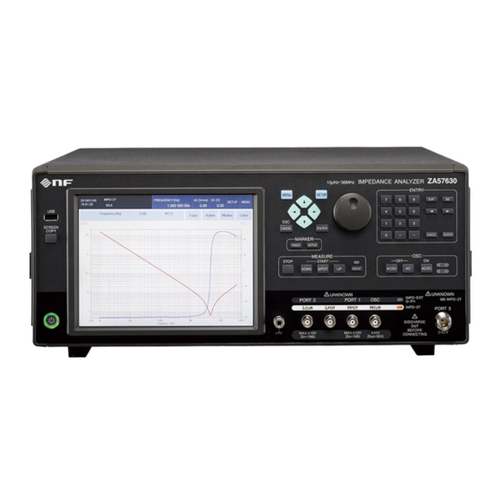
NF ZA57630 Instruction Manual (246 pages)
IMPEDANCE ANALYZER
Brand:
NF
| Category:
Measuring Instruments
| Size: 5 MB
Table of Contents
Table of Contents
10
Introduction
6
Table of Contents
10
Features
16
Applications
17
Operating Principle
18
Figure 1-1 Block Diagram
18
2. Preparation before Use
23
Preparation before Use
23
Checking before Use
24
Assembly and Installation
26
General Precautions for Installation
26
Installation Conditions
26
Rack Mounting
27
Figure 2-1 Rack Mount Kit Assembly Drawing (JIS)
28
Figure 2-2 Rack Mount Kit Assembly Drawing (EIA)
29
Figure 2-3 Rack Mount Dimensions (JIS)
30
Figure 2-4 Rack Mount Dimensions (EIA)
31
Grounding and Power Supply Connection
32
Simple Operation Check
34
Calibration
35
3. Panel Operations
37
Panel Operations
37
Figure 3-1 Front Panel
38
Functions and Operations of Panel Parts
38
Figure 3-2 Rear Panel
39
Figure 3-3 Functions of Measurement Connectors
44
Input and Output Connectors
44
Figure 3-4 Functions of Measurement Connectors (Measurement Mode: IMPD−3T)
45
Figure 3-5 Functions of Measurement Connectors (Measurement Mode: IMPD−2T)
46
Figure 3-6 Function of DC BIAS out Connector
47
Figure 3-7 Function of 10 Mhz REF in Connector
48
Figure 3-8 Function of 10 Mhz REF out Connector
49
Figure 3-9 Handler Interface Connector Pin Assignment Diagram
50
Figure 3-10 Equivalent Circuit of Handler Interface
53
Figure 3-11 AUX Connector Pin Assignment Diagram
53
Figure 3-12 I/O Connector Equivalent Circuit of AUX Connector
54
Figure 3-13 Screen Immediately after Startup
55
Figure 3-14 Status Display Area
55
Overview of the Operation Screens
55
Figure 3-15 Measurement Condition Display Area
56
Figure 3-16 Basic Menu Operation Area
57
Figure 3-17 Marker Display Area
57
Figure 3-18 Marker Operation Area
57
Figure 3-19 Menu Display Example
59
Figure 3-20 Switching Menu (Top Menu)
59
Figure 3-21 Menu Layer Operation
60
Figure 3-22 Function Keys
60
Figure 3-23 Numerical Settings (Immediate Settings)
61
Figure 3-24 Numerical Settings
62
Figure 3-26 Palette Operations (Immediate Settings)
63
Figure 3-27 Text Settings (Immediate Settings)
64
Figure 3-28 Switching Text Input Palette
65
Figure 3-29 Execution Operations (Requiring Confirmation)
66
Figure 3-30 Graph Display Styles
66
Operation Tree
68
Setting Screen Reference
78
Figure 3-25 List Operations (Immediate Settings)
108
Initial Settings
147
4. Basic Operations
159
Basic Operations
159
Check before Turning on the Power
160
Display and Operation When Power Is Turned on
160
Turning the Power on and off
160
Restoration of Settings at Power on
161
Startup Screen and Operation on Startup
162
Common Operations
163
Simple Operation for First Time Use
163
Measuring Impedance (Measurement Mode: IMPD−EXT)
164
Figure 4-2 Impedance Measurement Connection Example 2 (IMPD−EXT, Measurement of DUT with Grounding)
165
Figure 4-4 Impedance Measurement Connection Example 4 (IMPD−3T)
167
Measuring Impedance (Measurement Mode: IMPD−3T)
167
Figure 4-5 How to Check Operation Using 100 Ω RESISTOR (IMPD−3T)
168
Figure 4-6 Impedance Measurement Connection Example 5 (IMPD−2T)
169
Measuring Impedance (Measurement Mode: IMPD−2T)
169
Figure 4-7 Gain and Phase Measurement Connection Example
170
Measuring Gain and Phase (Measurement Mode: G−PH)
170
Setting Measurement Signals
171
Measurement Controls
176
Setting Sweep Measurement
177
Setting Spot Measurement
183
5. Specifications
185
Specifications
185
Measurement Modes
186
Measurement Value Display Ranges
187
Measurement Connectors (Measurement Mode IMPD−EXT)
189
Measurement Connectors (Measurement Mode IMPD−3T)
192
Measurement Connectors (Measurement Mode IMPD−2T)
195
Measurement Connectors (Measurement Mode G−PH)
198
Measured Signal Control Section
202
Measurement Accuracy
204
Measurement Processing Section
215
Display Section
219
External Memory
220
Memory
220
External Input/Output Function
221
Miscellaneous Specifications
223
Figure 5-1 External Dimensions
224
Advertisement
Advertisement
Related Products
NF ZM2371
NF ZM2372
NF ZM2376
NF FRA5014
NF FRA5022
NF FRA5087
NF FRA5097
NF FRA51602
NF FRA51615
NF Categories
Amplifier
Measuring Instruments
AC Power Distribution
Portable Generator
Power Supply
More NF Manuals
Login
Sign In
OR
Sign in with Facebook
Sign in with Google
Upload manual
Upload from disk
Upload from URL