Table of Contents
Advertisement
Advertisement
Table of Contents

Related Manuals for La Crosse Technology WS-9013U


Summary of Contents for La Crosse Technology WS-9013U
- Page 1 WS-9013U Wireless 433 MHz Radio-controlled Weather Station Instruction Manual...
-
Page 2: Table Of Contents
Topic Inventory of Contents/Additional Equipment About WWVB Quick Set-Up Guide Detailed Set-Up Guide Battery Installation Program Mode Programming Sequence Function Keys 12/24 Hour Time Setting Time Zone Setting Daylight Saving Time Setting Time Setting (WWVB & Manual) Setting Day, Date and Year Selecting °F or °C Setting the LCD Contrast Features... -
Page 3: Inventory Of Contents/Additional Equipment
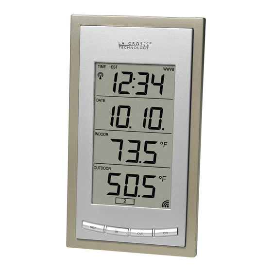
Date LCD Indoor LCD Outdoor LCD Figure 1 ADDITIONAL EQUIPMENT (not included) 1. Two, fresh AA 1.5V batteries for indoor weather station. 2. Two, fresh AA 1.5V batteries for remoter temperature sensor. 3. One, Philips screwdriver for mounting. Figure 2 Mounting... -
Page 4: About Wwvb
However, due to the nature of the earth’s ionosphere, reception is very limited during daylight hours. The weather station will search for a signal every night when reception is best. The WWVB radio station derives its signal from the NIST Atomic clock in Boulder, Colorado. -
Page 5: Quick Set-Up Guide
NOTE: Fog and mist will not harm your remote temperature sensor but direct rain must be avoided. To complete the set up of your indoor weather station after the 10 minutes have passed please follow the steps on pages 8 and 9. -
Page 6: Detailed Set-Up Guide
4. Replace the battery cover by sliding upwards. Be sure battery cover is on securely. B. INDOOR WEATHER STATION 1. Remove the battery cover. To do this, insert a solid object in the space provided at the lower-... -
Page 7: Program Mode
If you do leave the program setting (or want to program a specific setting) follow each instructional step to program that setting. I. PROGRAMMING SEQUENCE The sequence for programming the indoor weather station and the default (factory) settings are: 1. 12/24 hour time setting 2. Time Zone 3. -
Page 8: Function Keys
II. FUNCTION KEYS The function keys are operated by pressing the key corresponding to the operation that you want to perform. II. 12 OR 24 HOUR TIME SETTING 1. Press and hold the “SET” button for 3 seconds or until “12 h”... -
Page 9: Daylight Saving Time Setting
4. Select your appropriate time zone using “CH” button. During selection of the Time Zone, letter abbreviations for the time zones found in North America will flash across the top of the TIME LCD. Observe the chart below, showing corresponding abbreviations, time zones, and codes. -
Page 10: Time Setting (Wwvb & Manual)
6:00 AM—when there is less atmospheric interference. To keep your time as accurate as possible, the weather station conducts a WWVB search every night between these hours and overrides any manually set time. The WWVB tower icon (appearing in the TIME... -
Page 11: Setting Day, Date And Year
Press and release the “SET” button to confirm the hour setting and to advance to the minute setting mode. The minute digits should be flashing. Press and release the "CH” button to change the minutes—increasing the minutes by increments of 1 with each press of the “CH” button. Press and release the “SET”... -
Page 12: Selecting °F Or °C
5. The numeric-month will be flashing in the DATE LCD. Press and release the “CH” button to select to the current month. 6. Press and release the “SET” button to confirm the numeric- month, and to enter the numeric-day setting mode. 7. -
Page 13: Setting The Lcd Contrast
VIII. SETTING THE LCD CONTRAST 1. Press and hold the “SET” button for 3 seconds or until “12h” or “24h” flashes in the DATE LCD. 2. Press and release the “SET” button 10 more times to reach the LCD contrast setting mode. 3. -
Page 14: Indoor Temperature
FEATURES OF THE WS-9013U WWVB Tower Icon (indicates time reception) Remote Temperature Sensor Channel Indicator I. INDOOR TEMPERATURE The current indoor is displayed in the INDOOR LCD and is updated every 10 seconds. II. OUTDOOR TEMPERATURE The outdoor temperature is viewed in the OUTDOOR LCD. The outdoor temperature is updated every five minutes. -
Page 15: Minimum & Maximum Records
III. MINIMUM AND MAXIMUM TEMPERATURE RECORDS The WS-9013U keeps a record of the MINIMUM and MAXIMUM temperature and the time and date of their occurrence—for both the indoor and outdoor modes. A. VIEWING THE INDOOR TEMPERATURE RECORDS 1. Press the “IN” button once. “MIN” appears in the upper... -
Page 16: Units (Set-Up, Viewing & Operation)
IV. ADDING OUTDOOR REMOTE CONTROL SENDERS (OPTIONAL) The WS-9013U is able to receive signals from 3 different remote temperature sensors. The remote temperature sensor model(s) that you choose will come with their own set of instructions. instructions for a complete guide to setting up. Following are some brief instructions for the basic set-up of remote temperature sensor units with the WS-9013U. - Page 17 4. In sequential order, install batteries (follow the same battery installation procedures seen in section I. A) of the Detailed Set-Up Guide). 5. Install batteries into the indoor weather station. 6. Follow the Detailed Set-Up Guide for programming and operating instructions.
-
Page 18: Mounting
MOUNTING Note: Before permanently mounting ensure that the indoor weather station is able to receive WWVB signals from the desired location. Also, extreme and sudden changes in temperature will decrease the accuracy of the indoor weather station. To achieve a true temperature reading, avoid mounting where direct sunlight can reach the remote temperature sensor. - Page 19 ensure a secure hold. The mounting surface should be smooth and flat. 2) Remove the protective strip from one side of the tape. Adhere the tape to the designated area on the back of the mounting bracket. 3) Remove the protective strip from the other side of the tape.
-
Page 20: Troubleshooting
Problem: No reception of WWVB time signal. Solution: 1) Wait overnight for signal. 2) Be sure indoor weather station is at least 6 feet from any electrical devices such as televisions, computers or other radio-controlled clocks. 3) Remove batteries for five minutes, reinsert and leave the unit alone overnight without pressing buttons. -
Page 21: Specifications
Outdoor: Indoor temperature checking interval: Outdoor temperature checking interval: (Remote Temperature Sensor) Outdoor temperature reception: (Indoor Weather Station) Transmission Range: Power Supply: Indoor Weather Station: Remote Temperature Sensor: Battery life cycle: Recommended battery type: Dimensions (H x W x D) -
Page 22: Warranty Information
Before sending the indoor weather station in for repairs, contact La Crosse Technology. The indoor weather station will be repaired or replaced with the same or similar model. This warranty does not cover any defects resulting from improper use, unauthorized repairs, faulty batteries, or the indoor weather stations inability to receive a signal due to any source of interference. - Page 23 For warranty work, technical support, or information contact La Crosse Technology 190 Main St. La Crescent, MN 55947 Phone: 507.895.7095 Fax: 507.895.8000 e-mail support@lacrossetechnology.com (warranty work) sales@lacrossetechnology.com (information on other products) Website www.lacrossetechnology.com FCC ID: OMO-01RX (receiver), OMO-01TX (transmitter) THIS DEVICE COMPLIES WITH PART 15 OF THE FCC RULES. OPERATION IS SUBJECT TO THE FOLLOWING TWO CONDITIONS: 1.
- Page 24 This handbook may contain mistakes and printing errors. The information in this handbook is regularly checked and corrections made in the next issue. We accept no liability for technical mistakes or printing errors, or their consequences. All trademarks and patents are acknowledged.
Need help?
Do you have a question about the WS-9013U and is the answer not in the manual?
Questions and answers