Table of Contents
Advertisement
Available languages
Available languages
Item #1007 532 504, 1007 532 510, 1007 532 507
Model #56050, 56051, 56059
UL Model #EF200T(A)-52
USE AND CARE GUIDE
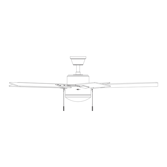
CORWIN 52-INCH CEILING FAN
Questions, problems, missing parts? Before returning to the store,
call Hampton Bay Customer Service
8 a.m. - 7 p.m., EST, Monday - Friday, 9 a.m. - 6 p.m., EST, Saturday
1-855-HD-HAMPTON
HAMPTONBAY.COM
To view an instructional video on how to install this product:
1. Go to www.homedepot.com and enter either the Item or Model number, found in the top
right corner of the cover of this instruction manual, in the search eld.
2. Click on your product from the list of search results and click on the video link in the
"Product Overview" section.
THANK YOU
We appreciate the trust and confidence you have placed in Hampton Bay through the purchase of this ceiling fan. We strive to continually create
quality products designed to enhance your home. Visit us online to see our full line of products available for your home improvement needs.
Thank you for choosing Hampton Bay!
Advertisement
Chapters
Table of Contents

Related Manuals for HAMPTON BAY CORWIN 56050


Summary of Contents for HAMPTON BAY CORWIN 56050
- Page 1 THANK YOU We appreciate the trust and confidence you have placed in Hampton Bay through the purchase of this ceiling fan. We strive to continually create quality products designed to enhance your home. Visit us online to see our full line of products available for your home improvement needs.
-
Page 2: Table Of Contents
Table of Contents Table of Contents ..............2 Assembly ................7 Safety Information ............... 2 Operation ................12 Warranty ................3 Care and Cleaning ............. 13 Pre-Installation ..............3 Troubleshooting ..............13 Installation ................6 Safety Information READ AND SAVE THESE INSTRUCTIONS. WARNING: To reduce the risk of personal injury, do not bend the blade brackets (also referred to as To reduce the risk of electric shock, ensure the electricity has been... -
Page 3: Warranty
A certain amount of “wobble” is normal and should not be considered a defect. Servicing performed by unauthorized persons shall render the warranty invalid. There is no other express warranty. Hampton Bay hereby disclaims any and all warranties, including but not limited to those of merchantability and fitness for a particular purpose to the extent permitted by law. - Page 4 Pre-Installation (continued) HARDWARE INCLUDED NOTE: Hardware not shown to actual size. Part Description Quantity Plastic wire connector Hanger pin Locking pin Blade arm screws Blade attachment screw washer Blade bracket screws Pull chain...
- Page 5 Pre-Installation (continued) PACKAGE CONTENTS Part Description Quantity Part Description Quantity Slide-on mounting bracket Blade bracket (inside canopy) Blade Canopy Blade support plate Canopy bottom cover IMPORTANT: This product and/or components are governed by Ball/downrod assembly one or more of the following U.S. Patents: 5,947,436; 5,988,580; Fan motor assembly 6,010,110;...
-
Page 6: Installation
Installation MOUNTING OPTIONS NOTE: You may need a longer downrod to maintain WARNING: To reduce the risk of fire, electric shock, proper blade clearance when installing on a steep, sloped or personal injury, mount the fan to an outlet box ceiling. - Page 7 Assembly - Standard Ceiling Mount Preparation for standard mounting Routing the wires □ □ Remove the canopy bottom cover (C) from the canopy (B) by Route the wires exiting the top of the fan motor assembly (E) turning the bottom cover counterclockwise until it unlocks. through the center of the canopy bottom cover (C).
- Page 8 Assembly - Hanging the Fan Attaching the fan to the electrical Hanging the fan WARNING: To reduce the risk of fire, electric shock, or other WARNING: When using the standard ball/downrod mounting, personal injury, mount the fan to an outlet box marked the tab in the ring at the bottom of the mounting bracket “Acceptable for fan support of 35 lb (15.9 kg) or less”...
-
Page 9: Assembly
Assembly - Hanging the Fan (continued) Making the electrical connection Wrapping the extra wire IMPORTANT: Use the plastic wire connectors (AA) supplied with NOTE: Follow this step ONLY if you did not cut the extra length off your fan. Secure the connectors with electrical tape and ensure from the wires coming from the ceiling fan. - Page 10 Assembly - Hanging the Fan (continued) Attaching the canopy □ Align the locking slots of the canopy (B) with the two screws (PP) and alignment post (II) in the mounting bracket (A). □ Push up the canopy (B) and turn clockwise until the alignment post (II) engages to the round hole and the screws (PP) engage to the key slots.
- Page 11 Assembly - Attaching the Fan Blades (continued) Attaching the blade assemblies to the motor □ Attach the blade assembly to the motor assembly (E) by aligning the screw holes on the blade bracket (J) with the screw holes on the bottom of the fan motor assembly (E). Insert the screws (FF) and screw washers (EE) into the holes on the blade bracket (J) and through the holes on the bottom of the fan motor assembly (E), and tighten each screw to...
- Page 12 Assembly - Attaching the Light Kit (continued) Installing the glass shade WARNING: Do not overtighten when installing the glass shade into the light kit. Allow the glass shade to cool completely before removing. □ With the power off, install the two LED bulbs (H) by screwing them into the light bulb sockets.
-
Page 13: Care And Cleaning
Care and Cleaning WARNING: Make sure the power is off before cleaning your fan. □ Because of the fan’s natural movement, some connections may become loose. Check the support connections, brackets, and blade attachments twice a year. Make sure they are secure. It is not necessary to remove the fan from the ceiling. □... - Page 14 Questions, problems, missing parts? Before returning to the store, call Hampton Bay Customer Service 8 a.m. - 7 p.m., EST, Monday - Friday, 9 a.m. - 6 p.m., EST, Saturday 1-855-HD-HAMPTON HAMPTONBAY.COM Retain this manual for future use.
- Page 15 GRACIAS Apreciamos la plena confianza que has depositado en Hampton Bay con la compra de este ventilador de techo. Nos esforzamos constantemente por crear productos de calidad diseñados para tu hogar. Visítanos por Internet para ver nuestra línea completa de productos disponibles a fin de...
- Page 16 Tabla de contenido Tabla de contenido .............. 2 Ensamblaje ................7 Información de seguridad........... 2 Operación ................12 Garantía ................3 Mantenimiento y limpieza ..........13 Preinstalación ..............3 Solución de problemas ............. 13 Instalación ................6 Información de seguridad LEE Y GUARDA ESTAS INSTRUCCIONES.
-
Page 17: Garantía
Cualquier servicio prestado por personal no autorizado invalidará la garantía. No hay ninguna otra garantía expresa. Por este medio y en el alcance permitido por la ley, Hampton Bay queda exonerado de toda garantía, incluso, pero sin limitarse a ellas, aquellas de comercialización e idoneidad para un fin determinado. La duración de cualquier garantía implícita que no pueda exonerarse se limita al plazo especificado en la garantía explícita. - Page 18 Preinstalación (continuación) HERRAJES INCLUIDOS NOTA: Los herrajes no se muestran en su tamaño real. Pieza Descripción Cantidad Conector plástico para cables Pasador de soporte Pasador de cierre Tornillos del brazo de aspa Arandela de tornillo para el montaje de aspas Tornillos para soporte de aspas Interruptor de cadena...
- Page 19 Preinstalación (continuación) CONTENIDO DEL PAQUETE Pieza Descripción Cantidad Pieza Descripción Cantidad Soporte de montaje deslizante Soporte de aspa (dentro de la cubierta) Aspa Cubierta Placa de soporte de aspa Tapa del fondo de la cubierta Conjunto del tubo bajante/esfera IMPORTANTE: Este producto y/o sus componentes están protegidos por una o más de las siguientes patentes de los EE.
-
Page 20: Instalación
Instalación OPCIONES DE MONTAJE NOTA: Tal vez necesites un tubo bajante más largo para ADVERTENCIA: Para reducir el riesgo de incendio, descarga mantener la altura mínima adecuada de las aspas, al eléctrica o lesiones personales, instala en una caja eléctrica instalar el ventilador en un techo inclinado. - Page 21 Ensamblaje - Montaje estándar en techo Preparación para montaje estándar Cómo tender los cables □ □ Inserta los cables que salen por la parte superior del conjunto Retira la tapa inferior (C) de la cubierta (B) girándola hacia la motor-ventilador (E) a través del centro de la tapa inferior de la izquierda hasta liberarla.
- Page 22 Ensamblaje - Cómo colgar el ventilador Cómo fijar el ventilador a la caja Cómo colgar el ventilador eléctrica ADVERTENCIA: Para reducir el riesgo de incendio, descarga ADVERTENCIA: Cuando uses el montaje estándar del tubo eléctrica o lesiones personales, instala sólo en una caja eléctrica bajante/esfera, la pestaña en el aro de la parte inferior del soporte marcada como “Apropiada para sostener ventiladores de 35 lb de montaje tiene que encajar en la ranura de la esfera de soporte.
-
Page 23: Ensamblaje
Ensamblaje - Cómo colgar el ventilador (continuación) Cómo hacer las conexiones eléctricas Cómo enroscar el cable sobrante IMPORTANTE: Usa los conectores de cables plásticos (AA) incluidos con NOTA: Sigue estos pasos SOLAMENTE si no cortaste el cable sobrante el ventilador. Sujeta los conectores con cinta de electricista y asegúrate del ventilador de techo. - Page 24 Ensamblaje - Cómo colgar el ventilador (continuación) Cómo montar la cubierta □ Alinea las ranuras de cierre de la cubierta (B) con los dos tornillos (PP) y el poste de alineación (II) del soporte de montaje (A). □ Empuja hacia arriba la cubierta (B) y gírala hacia la derecha hasta que el poste de alineación (II) se enganche en el orificio redondo y los tornillos (PP) en las ranuras tipo ojo de cerradura.
- Page 25 Ensamblaje - Cómo fijar las aspas del ventilador (continuación) Cómo conectar los ensamblajes de las aspas al motor □ Fija el aspa ensamblada al motor (E) alineando los orificios de tornillo en el brazo del aspa (J) con los orificios de tornillo en la parte inferior del conjunto motor-ventilador (E).
- Page 26 Ensamblaje - Cómo instalar el kit de luces (continuación) Cómo instalar la pantalla de vidrio ADVERTENCIA: No aprietes demasiado al instalar la pantalla de vidrio en el kit de luces. Espera que la pantalla de vidrio se enfríe completamente antes de retirarla. □...
-
Page 27: Mantenimiento Y Limpieza
Mantenimiento y limpieza ADVERTENCIA: Asegúrate de que la corriente esté cortada antes de limpiar el ventilador. □ Debido al movimiento natural del ventilador, algunas conexiones pueden aflojarse. Revisa dos veces al año las conexiones de soporte, los soportes y los accesorios de las aspas. Comprueba que estén seguros. No es necesario desmontar el ventilador del techo. □... - Page 28 ¿Preguntas, problemas, piezas faltantes? Antes de devolverlo a la tienda, llama al servicio al cliente de Hampton Bay de 8:00 a.m. a 7:00 p.m. (Hora Estándar del Este) entre lunes y viernes, y los sábados de 9:00 a.m. a 6:00 p.m. (Hora Estándar del Este).
Need help?
Do you have a question about the CORWIN 56050 and is the answer not in the manual?
Questions and answers