Table of Contents
Advertisement
Available languages
Available languages
Quick Links
Advertisement
Chapters
Table of Contents

Related Manuals for HAMPTON BAY Largo


Summary of Contents for HAMPTON BAY Largo
- Page 1 705 544 707 608 635 289 635 412 998 418 560 459 Largo Largo 1 22...
-
Page 2: Table Of Contents
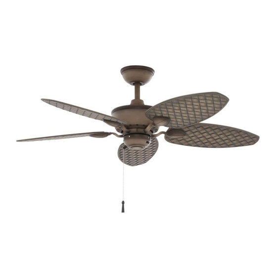
48” Largo Thank you for purchasing this Hampton Bay ceiling fan. This product has been manufactured with the highest standards of safety and quality. The finish of this fan is weather resistant, but over time will Ceiling Fan by Hampton Bay naturally weather and fade. -
Page 3: Safety Rules 1
READ AND SAVE THESE INSTRUCTIONS Do not use water or detergents when cleaning the fan or fan To reduce the risk of electric shock, insure electricity blades. A dry dust cloth or lightly dampened cloth will be has been turned off at the circuit breaker or fuse box suitable for most cleaning. -
Page 4: Unpacking Your Fan
Unpack your fan and check the contents. You should have the following items: Electrical & Mounting Hardware 1. Slide-On Mounting Plate (inside canopy) 7. Blades (5) (3 plastic wire connectors, 1 hanger pin, 1 2. Ball/Downrod Assembly 8. Blade Bracket (Flange) Set (5) locking pin) with blade bracket screws pre-installed 3. -
Page 5: Installing Your Fan 3
COMMONLY USED SUPPORT Figure 2 LIGHTING FIXTURES installation hanger bar as shown in Figure 4 ACCEPTABLE SUPPORT (available at your Hampton Bay retailer). MAY NEED TO BE REPLACED. CONSULT A QUALIFIED ELECTRICIAN IF IN DOUBT. Installing Your Fan 3. - Page 6 Hanging the Fan each section of the instructions will note the 3. Route the wires exiting the top of the different procedures to follow for the two fan motor through the decorative motor collar cover then the canopy ring. Make sure REMEMBER types of installation.
- Page 7 “Close-to-Ceiling” Mounting 4. Loosen, but do not remove, the set 6. Align the mounting holes with the holes screw on the collar on the top of the in the motor and fasten, using the three 1. Remove the canopy ring from the canopy motor housing.
- Page 8 hook provided by utilizing one of the Follow the steps below to connect the fan holes at the outer rim of the ceiling canopy to your household wiring. Use the wire WHEN USING THE STANDARD BALL/DOWN- (Figure 12). If using standard mounting, seat ROD MOUNTING, THE TAB IN THE RING AT THE connecting nuts supplied with your fan.
- Page 9 Finishing the Fan 5. Turn the wire connecting nuts upward and SUPPLY CIRCUIT push the wiring into the outlet box. Installation TO REDUCE THE RISK OF FIRE OR ELECTRIC STANDARD CEILING MOUNTING SHOCK, DO NOT USE A WALL MOUNTED SOLID Switch STATE SPEED CONTROL WITH THIS FAN.
- Page 10 Attaching the 3. Fasten the blade assembly to the motor by CLOSE-TO-CEILING MOUNTING inserting the alignment post into the slot on 1. Carefully unhook the fan from the mount- Fan Blades the bottom of the motor and tightening the ing bracket and align the locking slots of blade bracket screws.
-
Page 11: Operating Your Fan 9
Blade Balancing TO REDUCE THE RISK OF PERSONAL INJURY, All blades are grouped by weight. Because nat- DO NOT BEND THE BLADE HOLDERS WHILE INSTALLING, BALANCING THE BLADES, OR ural woods vary in density, the fan may wobble CLEANING THE FAN. DO NOT INSERT FOREIGN even though the blades are weight matched. -
Page 12: Care Of Your Fan
Troubleshooting Care of Your Fan Here are some suggestions to help you Problem Solution maintain your fan. Fan will not start Check main and branch circuit fuses or breakers 1. Because of the fan’s natural movement, Check line wire connections to the fan and switch wire connections in some connections may become loose. -
Page 13: Specifications 11
GROSS FAN SIZE SPEED VOLTS AMPS WATTS CUBE FEET WEIGHT WEIGHT 0.25 13.2 2257 21.3 23.5 48” 0.38 30.6 3466 1.43’ High 0.55 66.6 5034 These are approximate measures. They do not include Amps and Wattage used by the light kit. Distributed by Your Other Warehouse LLC 12100 Little Cayman Dr. -
Page 14: Warranty Information
You must present a copy of the original Hampton Bay also warrants that all other fan parts, excluding any glass or acrylic blades, to be free purchase receipt to obtain warranty service. - Page 15 Largo de 48" Gracias por comprar este ventilador de techo de Hampton Bay. Este producto se ha fabricado con las normas de seguridad y calidad más altas. El acabado Ventilador de techo de Hampton Bay de este ventilador es resistente a la intemperie, pero con el tiempo, exhibirá...
-
Page 16: Normas De Seguridad
LEE LAS INSTRUCCIONES Y GUÁRDALAS Para evitar lesiones, o daños al ventilador y otros objetos; ten cuidado Para disminuir el riesgo de descarga eléctrica, asegúrate de al trabajar cerca del ventilador o al limpiarlo. que la electricidad ha sido apagada en el cortacircuitos o la caja de fusibles antes de comenzar la instalación. -
Page 17: Cómo Desempacar El Ventilador 2
Desempaca tu ventilador y revisa el contenido. Deberá tener las siguientes piezas: Herrajes de montaje y electricidad 1. Placa de montaje deslizante 6. Cubierta decorativa del collarín del motor (3 conectores plásticos de cable, 1 pasador (dentro de la cubierta) 7. -
Page 18: Cómo Instalar El Ventilador
Nota: Tal vez necesites un tubo bajante más Caja Si no hay una caja eléctrica existente, entonces lee largo para mantener la altura mínima adecuada eléctrica las siguientes instrucciones. Desconecta la energía de las aspas al instalar el ventilador en un techo retirando los fusibles o apagando los cortacircuitos. - Page 19 Cómo colgar el con las siguientes instrucciones. Cuando sea 3. Inserta los cables que salen por la parte necesario, cada sección de las instrucciones superior del motor del ventilador, primero, a ventilador indicará los diferentes procedimientos a seguir través de la cubierta decorativa del collarín del motor y luego, por el aro de la cubierta.
- Page 20 Montaje “Cerca del Techo” 4. Afloja, sin quitarlo, el tornillo en el collarín 6. Alinea los orificios de montaje con los ubicado en la parte superior de la carcasa del orificios del motor y asegura con los tres 1. Retira el aro en la cubierta, girando a la motor.
- Page 21 de los orificios en el borde exterior de la cubierta Sigue estos pasos para conectar tu ventilador a tu de techo (Figura 12). Si usas el montaje estándar, circuito doméstico. Usa las tuercas de conexión de CUANDO USES EL MONTAJE DE TUBO BAJANTE Y asienta la bola de soporte en el casquillo de la placa cables que vienen con tu ventilador.
- Page 22 Finalizar la 5. Gira las tuercas de conexión del cable hacia CIRCUITO DE SUMINISTRO arriba y coloca el cableado dentro de la caja instalación eléctrica. del ventilador Interruptor MONTAJE DE TECHO ESTÁNDAR Caja eléctrica PARA REDUCIR RIESGO INCENDIO DESCARGA ELÉCTRICA, UTILICES ESTE CUANDO USES EL MONTAJE DE TUBO BAJANTE Y...
- Page 23 Cómo montar 3. Ajusta el brazo del aspa al motor insertando MONTAJE CERCA DEL TECHO el poste de alineación dentro de la ranura las aspas del 1. Con cuidado desengancha el ventilador del de la parte inferior del motor y aprieta los soporte de montaje y alinea las ranuras de tornillos del soporte del aspa.
-
Page 24: Cómo Operar El Ventilador
Equilibrar las aspas PARA REDUCIR RIESGO LESIONES Todas las aspas se agrupan por peso. Como las PERSONALES, NO DOBLAR LOS SOPORTES DE LAS maderas naturales varían en densidad, el ventilador ASPAS DURANTE LA INSTALACIÓN, COMPENSACIÓN puede oscilar aunque las aspas tengan el mismo peso. DE LAS ASPAS O LIMPIEZA DEL VENTILADOR. -
Page 25: Cuidado Del Ventilador
Solución de problemas Cuidado del ventilador Aquí tienes algunas sugerencias para el Problema Solución mantenimiento de tu ventilador. El ventilador no Verifica fusibles o disyuntores principales y secundarios. 1. Debido al movimiento natural del ventilador, enciende Verifica conexiones de cables en línea al ventilador y conexiones de algunas conexiones pueden... -
Page 26: Especificaciones
PIES PESO PESO TAMAÑO VELOCIDAD VOLTIOS AMPERIOS VATIOS CÚB. X PIES CÚB. NETO BRUTO MIN. Baja 0.25 13.2 2257 21.3 23.5 48” Media 0.38 30.6 3466 1.43’ Alta 0.55 66.6 5034 Estas medidas son aproximadas. No incluyen ni el amperaje ni el vataje consumido por el kit de luces. Distribuido por Your Other Warehouse LLC 12100 Little Cayman Dr. -
Page 27: Información De La Garantía 12
Hampton Bay garantiza de por vida, a partir de la fecha de compra por el comprador original, que el motor del ventilador no presenta defectos de fabricación ni de material desde la fecha de salida de la Usted debe presentar una copia del fábrica.
Need help?
Do you have a question about the Largo and is the answer not in the manual?
Questions and answers