Table of Contents
Advertisement
Quick Links
DIGITAL ELECTRONIC
REFRIGERATION UNITS
CONTROLLER
OPERATING INSTRUCTIONS
09/14 - cod.: ISTR_M_B05-_E_01_--
ASCON TECNOLOGIC S.r.l.
VIA INDIPENDENZA 56
27029 VIGEVANO (PV) ITALY
TEL.: +39 0381 69871
FAX: +39 0381 698730
http:\\www.ascontecnologic.com
e-mail: info@ascontecnologic.com
FOREWORD
This
manual
necessary for the product to be installed
correctly
maintenance and use; we therefore recommend
that the utmost attention is paid to the following
instructions and to save it.
This
document
is
the
TECNOLOGIC which forbids any reproduction and divulgation
, even in part, of the document, unless expressly authorized.
ASCONT ECNOLOGIC reserves the right to make any formal or
functional changes at any moment and without any notice.
Whenever a failure or a malfunction of the device may cause
dangerous situations for persons, thing or animals, please
remember that the plant has to be equipped with additional
devices which will guarantee safety.
ASCON TECNOLOGIC and its legal representatives do not
assume any responsibility for any damage to people, things or
animals deriving from violation, wrong or improper use or in
any case not in compliance with the instrument's features
B05-
contains
the
and
also
instructions
exclusive
property
ASCON TECNOLOGIC - B05- - OPERATING INSTRUCTIONS - PAG. 1
INDEX
1
INSTRUMENT DESCRIPTION
1.1
GENERAL DESCRIPTION
1.2
FRONT PANEL DESCRIPTION
2
PROGRAMMING
2.1
FAST PROGRAMMING OF SET POINT
2.2
STANDARD MODE PARAMETERS PROGRAMMING
2.3
PARAMETER PROTECTION USING THE PASSWORD
2.4
CUSTOMIZED MODE PARAMETER PROGRAMMING
(PARAMETERS PROGRAMMING LEVEL)
2.5
RESET PARAMETERS TO DEFAULT VALUE/LEVEL
2.6
KEYBOARD LOCK FUNCTION
3
INFORMATION ON INSTALLATION AND USE
3.1
PERMITTED USE
3.2
MECHANICAL MOUNTING
3.3
ELECTRICAL CONNECTIONS
3.4
ELECTRICAL WIRING DIAGRAM
4
FUNCTIONS
4.1
ON / STAND-BY FUNCTION
4.2
"NORMAL"MODE, "ECONOMIC" MODE AND "TURBO"
MODE
4.3
MEASURING AND DISPLAY
4.4
DIGITAL INPUTS
4.5
OUTPUTS AND BUZZER CONFIGURATION
4.6
TEMPERATURE CONTROL
4.7
COMPRESSOR PROTECTION FUNCTION AND DELAY
AT POWER-ON
4.8
DEFROST CONTROL
4.8.1
AUTOMATIC DEFROST STARTS
4.8.2
MANUAL DEFROST
4.8.3
END DEFROST
4.8.4
DEFROSTS IN EVENT OF EVAPORATOR PROBE
ERROR
4.8.5
DEFROST DISPLAY LOCK
4.9
EVAPORATOR FANS CONTROL
4.10
ALARM FUNCTIONS
4.10.1
TEMPERATURE ALARMS
4.10.2
EXTERNAL ALARMS (DIGITAL INPUTS)
4.10.3
OPEN DOOR ALARM
4.10.4
MAIN VOLTAGE ALARMS
4.11
FUNCTION OF KEYS "U" AND "DOWN/AUX"
4.12
ACCESSORIES
4.12.1
PARAMETERS CONFIGURATION BY "A01"
4.12.2
TVR Y" REMOTE DISPLAY
5
PROGRAMMABLE PARAMETERS TABLE
6
PROBLEMS , MAINTENANCE AND GUARANTEE
6.1
SIGNALLING
6.2
CLEANING
6.3
GUARANTEE AND REPAIRS
7
TECHNICAL DATA
7.1
ELECTRICAL DATA
7.2
MECHANICAL DATA
7.3
MECHANICAL DIMENSIONS, PANEL CUT-OUT AND
information
MOUNTING
7.4
FUNCTIONAL DATA
for
its
7.5
INSTRUMENT ORDERING CODE
1 - INSTRUMENT DESCRIPTION
of
ASCON
1 .1 - GENERAL DESCRIPTION
The models B05 (Supply and outputs unit) and P03S or P05S
(Display unit) are a digital controller system with microprocessor
that is typically used in cooling applications that have temperature
control with ON/OFF regulation and defrosting control at time
intervals, by arrival at temperature or by length of time of
continuous
compressor, electric heating or hot gas/cycle inversion.
The appliance has special defrosting optimisation functions and
functions to reduce the amount of energy used by the controlled
system.
The instrument has up to 4 relay outputs, up to 3 inputs
configurable for PTC, NTC and Pt1000 temperature probes or
digital inputs.
compressor
operation
through
stopping
the
Advertisement
Table of Contents

Related Manuals for Ascon tecnologic B05


Summary of Contents for Ascon tecnologic B05
- Page 1 1 .1 - GENERAL DESCRIPTION TECNOLOGIC which forbids any reproduction and divulgation The models B05 (Supply and outputs unit) and P03S or P05S , even in part, of the document, unless expressly authorized. (Display unit) are a digital controller system with microprocessor...
-
Page 2: Front Panel Description
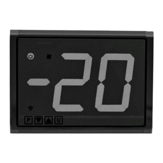
31 mm for the model P03S and 54 mm for the model P05S) 2 digits with sign -. On B05 unit there is a single LED that flashes to indicate the cor- The programming of operating parameters is done by 4 capacitive rect operation of the control unit. -
Page 3: Parameter Protection Using The Password
In this way it’s possible to have access to all the parameters, verify will appear on the display and all the keys functions will be availab- and modify the par. “PP”. le again. ASCON TECNOLOGIC - B05- - OPERATING INSTRUCTIONS - PAG. 3... - Page 4 4.1 - ON / STAND-BY FUNCTION Avoid placing the B05 unit and internal side of P03S or P05S in The instrument, once powered up, can assume 2 different environments with very high humidity levels or dirt that may create...
- Page 5 Setting “HC” = C3 gives the following operating cycle: is also possible to assign temperature alarms to it in order to give alarms relating to condenser malfunction (e.g. dirty/clogged condenser). ASCON TECNOLOGIC - B05- - OPERATING INSTRUCTIONS - PAG. 5...
-
Page 6: Digital Inputs
= ot - to control the compressor or however, the temperature the parameter “2t” while the action of Pr3 digital input is instanta- control device neous and cannot be delayed. ASCON TECNOLOGIC - B05- - OPERATING INSTRUCTIONS - PAG. 6... -
Page 7: Temperature Control
Via the parameter “HC” the following functions can be obtained: switching between the three modes, Normal, Eco and Turbo, as = C (Cooling) or = H (Heating) already described in the section on operating modes. ASCON TECNOLOGIC - B05- - OPERATING INSTRUCTIONS - PAG. 7... - Page 8 Instead if is desired all defrost to the same interval program "Sd" = (ot) "di." Automatic defrost function by interval is disable when “di” = oF. “Dynamic Defrost Intervals System”. ASCON TECNOLOGIC - B05- - OPERATING INSTRUCTIONS - PAG. 8...
-
Page 9: Manual Defrost
In event of evaporator probe error the defrosts occur at intervals The instrument start a defrost cycle when the compressor is turned "Ei" and duration "EE”. on continuously for the time "cd”. ASCON TECNOLOGIC - B05- - OPERATING INSTRUCTIONS - PAG. 9... -
Page 10: Evaporator Fans Control
“FL” (temperature too hot) or when it is These parameters are: ASCON TECNOLOGIC - B05- - OPERATING INSTRUCTIONS - PAG. 10... - Page 11 UniversalConf”, it’s possible to configure the operating parameters. Alarm “ot” output (compr.) other control outputs To use the device A01 it’s necessary that the device or instrument (“Fn”, “dF”, “Au”, “HE”). are being supplied. unchanged AL (4) ASCON TECNOLOGIC - B05- - OPERATING INSTRUCTIONS - PAG. 11...
-
Page 12: Programmable Parameters Table
/ 14 TLCNV and compressor stop TLCNV 4= External “AL” alarm TX/RX 5= External “AL” alarm with deactivation control outputs 6=Selection of active cable Set Point (SP-SPE) RS 485 GND B ASCON TECNOLOGIC - B05- - OPERATING INSTRUCTIONS - PAG. 12... - Page 13 -01 ÷ -59 cL = not used with output (sec) ÷ 01 ÷ 99 Defrosting interval oF/ -01 ÷ -59 (compressor) off (min) (min) ÷ 01 ÷ 99 (hrs) ASCON TECNOLOGIC - B05- - OPERATING INSTRUCTIONS - PAG. 13...
- Page 14 Alarms 0 / 1 / 2 / 3 -dF = Defrosting NC actions contact 0 = no actions OUT2 function: oF/ot/dF/ activate alarm see “o1” Fn/Au/At/ outputs AL/An/ -t/ -L/ ASCON TECNOLOGIC - B05- - OPERATING INSTRUCTIONS - PAG. 14...
- Page 15 Pr1 Power consumption: 4 VA approx. (without Loads connected) parameters relative to main voltage alarm Input/s: B05: 3 inputs for temperature probes: PTC (KTY 81-121, Low voltage alarm oF/ 9 ÷ 27 990Ω @ 25 ° C) or NTC (103AT-2, 10KΩ @ 25 ° C) or Pt1000...
-
Page 16: Mechanical Data
Mounting P05: Incorporated Flush in panel (2 mm max) in 124 x 85 mm hole Mounting B05: Incorporated Enclosure Connections P03, P05: mini extractable connectors Connections B05 (supply and outputs) : 6 poles AMP MATE-N- LOK .250 “ type connector min 10 mm RECOMMENDED... - Page 17 B = Blu c, d, e : INTERNAL CODES ff, gg : SPECIAL CODES Control Unit: B05- a b c d e f g h i j kk ll a : POWER SUPPLY H =Supply 100...240 VAC b : OUT1...
Need help?
Do you have a question about the B05 and is the answer not in the manual?
Questions and answers