Watts 909 Series Instruction, Installation, Maintenance And Repair Manual
Reduced pressure zone assemblies, reduced pressure detector assemblies
Hide thumbs
Also See for 909 Series:
- Installation instructions manual (24 pages) ,
- Installation, maintenance & repair (9 pages) ,
- Basic installation instructions (8 pages)
Advertisement
Available languages
Available languages
Quick Links
Installation, Maintenance, and Repair Manual
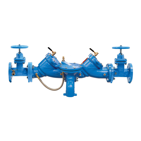
Series 909, LF909-FS, 909RPDA-FS
Reduced Pressure Zone Assemblies
Reduced Pressure Detector Assemblies
Sizes: 2
1
⁄
" – 10"
2
WARNING
!
Read this Manual BEFORE using this equipment.
Failure to read and follow all safety and use information can
result in death, serious personal injury, property damage, or
damage to the equipment.
Keep this Manual for future reference.
WARNING
!
Local building or plumbing codes may require modifications
to the information provided. You are required to consult
the local building and plumbing codes prior to installa-
tion. If the information provided here is not consistent with
local building or plumbing codes, the local codes should
be followed. This product must be installed by a licensed
contractor in accordance with local codes and ordinances.
WARNING
!
Need for Periodic Inspection/Maintenance: This product
must be tested periodically in compliance with local codes, but
at least once per year or more as service conditions warrant. If
installed on a fire suppression system, all mechanical checks,
such as alarms and backflow preventers, should be flow tested
and inspected in accordance with NFPA 13 and/or NFPA 25.
All products must be retested once maintenance has been
performed. Corrosive water conditions and/or unauthorized
adjustments or repair could render the product ineffective for the
service intended. Regular checking and cleaning of the product's
internal components helps assure maximum life and proper
product function.
WARNING
!
The installation and maintenance of backflow assemblies should
be performed by a qualified, licensed technician. Failure to do so
may result in a malfunctioning assembly.
Series 909/LF909-FS is equipped with an integrated flood sensor
that, when activated, triggers notification of potential flood events
from excessive relief valve discharges. An add-on sensor connection
is required to implement the activation. A retrofit sensor connection
kit is available for existing installations. See "Add-on and Retrofit
Sensor Connection Kits." on page 8.
Watts
Designed for inline servicing
Technology integrated for flood detection upon
activation with Sensor Connection Kit
NOTICE
For Australia and New Zealand, line strainers should be installed
between the upstream shutoff valve and the inlet of the backflow
preventer.
For field testing procedure, refer to Watts
sheets IS-TK-DL, IS-TK-9A, IS-TK-99E, and IS-TK-99D at
watts.com.
For other repair kits and service parts, refer to Backflow
Prevention Products Repair Kits & Service Parts price list
PL-RP-BPD at watts.com.
For technical assistance, contact your local Watts representative.
RP-IS-909-909RPDA-FS-1915468
®
909/LF909-FS
installation
®
Advertisement

Related Manuals for Watts 909 Series


Summary of Contents for Watts 909 Series
- Page 1 Prevention Products Repair Kits & Service Parts price list is required to implement the activation. A retrofit sensor connection PL-RP-BPD at watts.com. kit is available for existing installations. See “Add-on and Retrofit For technical assistance, contact your local Watts representative. Sensor Connection Kits.” on page 8.
-
Page 2: Considerations For Installation
Figure 2. Series 909/LF909-FS Relief Valve Discharge Rates • Normal discharge and nuisance spitting are accommodated by the use of a Watts air gap fitting and a fabricated indirect waste line. Floor drains of the same size MUST be provided in case of excessive dis- charge. - Page 3 WattsBox Insulated Enclosures; for more information, send for ES-WB. • The installation of a Watts air gap with the drain line terminating above a floor drain handles any normal discharge or nuisance spit- ting through the relief valve. However, floor drain size may need to...
- Page 4 A, B, and C. Remove all test equipment and open shutoff No. 2. Test Cock No. 1 Test Cock No. 2 For repair kits and parts, refer to Backflow Prevention Products Repair Kits & Service Parts price list PL-RP-BPD at watts.com.
- Page 5 Servicing First and Second Checks Sizes: 2 ⁄ " – 10" CAUTION No special tools First and second checks required to service are not interchangeable The spring assembly is an essential part of a check unit. Use care Series 909/LF909-FS when servicing the first and second checks.
- Page 6 Servicing the Relief Valve Figure 6. Relief Valve Assemblies by Valve Size Sizes: 2 ⁄ " – 10" Adapter O-ring CAUTION Use the clearance recommendations referenced below for servicing relief valve assemblies according to valve size. Figure 6 shows the Diaphragm differences between the assemblies by valve size.
- Page 7 Use second check. Watts No. 15 to eliminate water hammer. Replace defective second check assembly. In case of freezing, thaw, dis as sem ble, and inspect internal components.
- Page 8 Limited Warranty: Watts Regulator Co. (the “Company”) warrants each product to be free from defects in material and workmanship under normal usage for a period of one year from the date of original shipment.
- Page 9 PL-RP-BPD en watts.com. alivio. Se requiere una conexión de sensor adicional para implementar la activación.
-
Page 10: Consideraciones Para La Instalación
4 in a 10 in • La descarga normal y las molestas salpicaduras se solucionan (10.16 a 25.4 cm) mediante el uso de un accesorio de espacio de aire Watts y una ⁄ in a 3 in línea de residuos indirecta fabricada. DEBEN proporcionarse (6.35 cm a 7.62 cm) - Page 11 La descarga debe canalizarse a través de un accesorio de espacio de aire Watts canalizado a un desagüe del piso. • Watts recomienda la instalación en interiores o sobre el suelo en un recinto aislado. A V I S O Mín.
- Page 12 N.º 2. Para otros kits de reparación y piezas de repuesto, consulte la lista de precios de piezas de repuesto y kits de reparación de productos de prevención de reflujo PL-RP-BPD en watts.com.
- Page 13 Mantenimiento de las primeras y segundas retenciones Tamaños: 2 ⁄ in a 10 in (6.35 a 25.4 cm) No se requieren PR E C A U C I ÓN herramientas La primera y la segunda especiales para el retención no son intercambiables El ensamble de resorte es una parte esencial de una unidad de mantenimiento de la serie 909/LF909-FS...
- Page 14 Mantenimiento de la válvula Figura 6. Ensambles de válvulas de alivio por tamaño de válvula de alivio Junta tórica del adaptador Tamaños: 2 ⁄ in a 10 in (6.35 a 25.4 cm) P R E C A U C I Ó N Diafragma Utilice las recomendaciones de holgura a las que se hace referencia a continuación para el mantenimiento de los ensambles de válvulas Disco de la válvula de alivio...
- Page 15 B.4 Elimine la fuente de contrapresión excesiva o golpe congelación o el golpe de ariete de ariete en el sistema aguas abajo del dispositivo. han distorsionado la segunda Utilice la Watts N.º 15 para eliminar el golpe de retención. ariete. Reemplace el segundo ensamble de retención defectuoso.
- Page 16 Garantía limitada: Watts Regulator Co. (la “Compañía”) garantiza que cada producto estará libre de defectos en el material y mano de obra cuando se usen de forma normal durante un periodo de un año a partir de la fecha de envío original. En caso de que tales defectos se presenten dentro del período de garantía, la Compañía, a su discreción, remplazará o reacondicionará el producto sin cargo alguno.
Need help?
Do you have a question about the 909 Series and is the answer not in the manual?
Questions and answers