Table of Contents
Advertisement
Quick Links
INSTALLATION, OPERATION AND MAINTENANCE MANUAL
Warning
Please read carefully before proceeding with installation. Your failure to follow the instructions or
operating parameters may lead to the product's failure and possible damage to property.
Save manual for future reference
SERIES
WQC4 RO
Refer to enclosed warranty and operating parameters to ensure proper use with your water supply.
DISTRIBUTED BY:
Page 1
Manual Edition: 4/12/07
Advertisement
Table of Contents

Subscribe to Our Youtube Channel
Related Manuals for Watts WQC4 RO SERIES


Summary of Contents for Watts WQC4 RO SERIES
- Page 1 INSTALLATION, OPERATION AND MAINTENANCE MANUAL Warning Please read carefully before proceeding with installation. Your failure to follow the instructions or operating parameters may lead to the product’s failure and possible damage to property. Save manual for future reference SERIES WQC4 RO Refer to enclosed warranty and operating parameters to ensure proper use with your water supply.
- Page 2 NOTE: This manual is used for several variations of the same system. Your system may vary slightly from the pictures or descriptions contained in this manual. It is end users responsibility to ensure that this system is installed according to all local codes and regulations.
-
Page 3: Table Of Contents
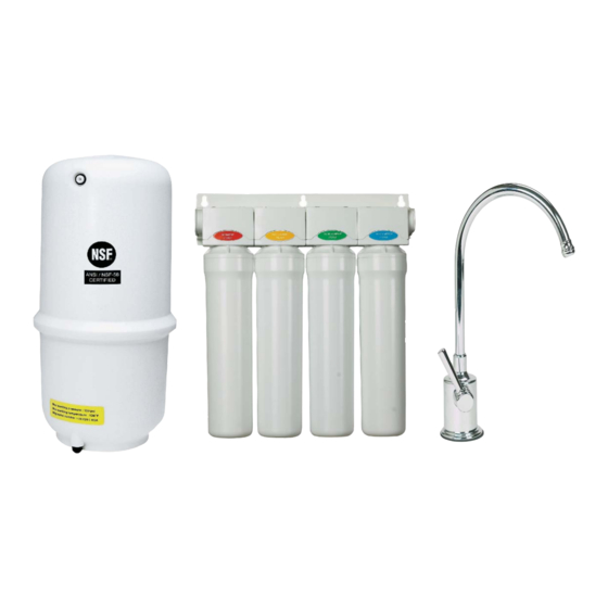
With proper installation and maintenance, this system will provide you with high quality water for years to come. All of Watts water enhancement products are rigorously tested. Table of Contents Operational Parameters ........................4 Contents of Reverse Osmosis System ....................4 Tools Recommended For Installation .................... -
Page 4: Operational Parameters
Operational Parameters Operating Temperatures: Maximum 100°F (37.8°C) Minimum 40°F (4.4°C) Operating Pressure: Maximum 85 psi (6.0 kg/cm Minimum 40 psi (2.80 kg/cm pH Parameters: Maximum 11 Minimum 2 Iron: Maximum 0.2 ppm TDS (Total Dissolved Solids) < 1800 ppm Turbidity <... -
Page 5: Drill A Hole For The Faucet In A Porcelain Sink
Drill a Hole for the Faucet in a Porcelain Sink Note: Some sinks are predrilled with 1 ½” or 1 ¼” diameter hole that you can use for your RO faucet. (If you are already using it for a sprayer or soap dispenser, see step 1). Porcelain sinks are extremely hard and can crack or chip easily. -
Page 6: Faucet Installation
WATTS Chrome (Top Mount) Faucet Installation Watts Top Mount Faucet Minimum Maximum Mounting Hole Size 1.00” 1.25” Torque on Toggle Bolt 5lb.in. (max) Gather and identify the faucet pieces. Step 6 Remove faucet base & faucet spout from their respective plastic bags. -
Page 7: Adapta Valve Installation
Adapta Valve Installation Confi guration for 1/2” Confi guration for 3/8” compression fi ttings compression fi ttings Cold Supply Supply Step 10 Locate the cold water supply under the sink. Step 11 Turn off the cold water supply to the faucet by turning the angle stop valve completely off. Step 12 Attach adapta valve as illustrated in the three photos above, choosing the confi... -
Page 8: Air Gap/Non Air Gap Installation
Non Air Gap Faucet Installation Air Gap Faucet Installation Page 8... -
Page 9: Drain Saddle Installation
Drain Saddle Installation Drain Saddle fi ts standard 1 ¼” – 1 ½” drain pipes Caution: If you have a garbage disposal, do not install the drain line near it. Installation of the drain line must be either above the disposal, or if a second sink drain is available, install it above the cross bar on the second sink. -
Page 10: White Tube Connection
White Tube Connection Note: The white tube will be cut into two pieces. One for the inlet and one for the tank. Connect White Tube from TANK Port on RO Module to the Tank Step 19 Position tank in desired location. Stand it upright or lay it on its side (using the black plastic stand). -
Page 11: 3/8" Black Tube Connection
3/8” Black Tube Connection from Faucet Note: The tubing must be as SHORT and STRAIGHT as possible to the drain saddle, making a downward slope from faucet to drain saddle to allow for proper drainage. Step 23 Measure the black tube from faucet to the black drain saddle and make a straight cut through tube. -
Page 12: Red Tube Connection (From Faucet)
Connect the Red Tube from Faucet to RO Module Step 25 a) Insert the fl ow control into the end of the red tubing coming from the faucet. b) Insert the end of red tubing into the fi tting labeled “Drain” on the back of the unit. Connect the Blue Tube from the Faucet to RO Module Step 26 Insert the blue 3/8”... -
Page 13: Cartridge Replacement
Cartridge Replacement Cartridge replacement is made easy with the Watts Kwik Change system. The cartridge heads contain built in check valves and shutoff valves so that the cartridges can be changed without shutting off the water supply or the storage tank. The head are also hinged to allow easy access to the cartridges. The following steps should be followed to change the cartridges. -
Page 14: Annual Maintenance
Annual Maintenance Storage Tank Sanitization Turn off the incoming water supply at the adapta valve. Step 1 Step 2 Open the faucet, allow the tank to empty, and then close the faucet. Step 3 Remove the tubing between the tank and the RO unit. Step 4 Drain the water from the tubing and pour one teaspoon of household bleach into the tubing. -
Page 15: Procedure For Extended Non-Use
Tank air pressure Turn off the incoming water supply at the adapta valve. Step 1 Open the faucet, allow the tank to empty, and then close the faucet Step 2 Check the pressure in the tank using a tire pressure gauge on the air valve. Step 3 The tank pressure should be between 5-7 psi. -
Page 16: Trouble Shooting
TROUBLE SHOOTING Problem Cause Solution 1. Low/Slow Production Low Water Pressure Assure a minimum of 40 psi incoming water pressure. Watts sells a booster pump if home water pressure is low. Make sure water supply is turned on and Adapta Valve is all the way open. -
Page 17: Service Record
Service Record Serial No. _____________________ Date of Purchase:__________ Date of Install:___________ Installed by:__________________ 3rd stage 2nd stage 4th stage 1st stage Date Membrane Carbon Carbon Sediment (2-5 years) (6 months) (1 year) (6 months) NOTES: Page 17... -
Page 18: Warranty Information
Limited Warranty This Reverse Osmosis System is warranted against defects in material and workmanship for a period of one year from the date of installation, not to exceed 2 years from the date of manufacture. Expendable items such as fi lter cartridges and membranes are not covered by this warranty. -
Page 19: Unit Drawing
ITEM PART # DESCRIPTION WQCS-10,11,13” SEDIMENT FILTER WQCC-10,11,13” PRE-CARBON FILTER WQCM-10,11,13” MEMBRANE FILTER(50 OR 100 GPD) WQGAC-10,11,13” POST CARBON FILTER FRO-132-WH 4 GALLON WHITE STEEL TANK ROPRO4-W RO ROPRO STORAGE TANK, WHITE PLASITC BV9014W 3/8” FEMALE ELBOW SHUT-OFF F116000 FCT TOP MOUNT CHROME, AIRGAP FAUCET F134007 RO ADAPT-A-VALVE SC500B38... - Page 20 Page 20...
Need help?
Do you have a question about the WQC4 RO SERIES and is the answer not in the manual?
Questions and answers